1995 JEEP CHEROKEE warning light
[x] Cancel search: warning lightPage 170 of 2198
ABS OPERATION AND SERVICE
INDEX
page page
ABS Component Serviceability............... 37
ABS Diagnostic Connector.................. 35
ABS Operation in Antilock Braking Mode........ 36
ABS Operation in Normal Braking Mode........ 35
ABS System Power-Up and Initialization........ 35
Acceleration Switch........................ 35
Acceleration Switch Installation............... 39
Acceleration Switch Operation................ 37
Acceleration Switch Removal................ 39
Combination Valve........................ 34
ECU Installation (XJ Models)................. 40
ECU Operation........................... 37
ECU Removal (XJ Models).................. 40
ECU Removal/Installation (YJ Models).......... 41
Electronic Control Unit (ECU)................ 34
Front Wheel Sensor Installation............... 38
Front Wheel Sensor Removal................ 38HCU Installation (XJ)....................... 43
HCU Installation (YJ)....................... 44
HCU Operation........................... 36
HCU Removal (XJ)........................ 41
HCU Removal (YJ)........................ 44
Hydraulic Control Unit (HCU)................. 33
Ignition Switch........................... 35
Master Cylinder/Power Brake Booster.......... 34
Rear Wheel Sensor Installation and Adjustment . . . 38
Rear Wheel Sensor Removal................ 38
Speed Sensor Air Gap..................... 37
System Description........................ 33
System Relays........................... 35
System Warning Light...................... 35
Wheel Speed Sensor Operation.............. 37
Wheel Speed Sensors..................... 34
SYSTEM DESCRIPTION
The Jeep antilock brake system (ABS) is an elec-
tronically operated, all wheel brake control system.
The system is designed to prevent wheel lockup
and maintain steering control during periods of high
wheel slip when braking. Preventing lockup is accom-
plished by modulating fluid pressure to the wheel
brake units.
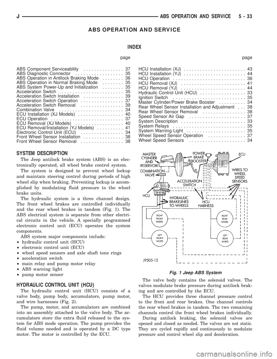
The hydraulic system is a three channel design.
The front wheel brakes are controlled individually
and the rear wheel brakes in tandem (Fig. 1). The
ABS electrical system is separate from other electri-
cal circuits in the vehicle. A specially programmed
electronic control unit (ECU) operates the system
components.
ABS system major components include:
²hydraulic control unit (HCU)
²electronic control unit (ECU)
²wheel speed sensors and axle shaft tone rings
²acceleration switch
²main relay and pump motor relay
²ABS warning light
²pump motor sensor
HYDRAULIC CONTROL UNIT (HCU)
The hydraulic control unit (HCU) consists of a
valve body, pump body, accumulators, pump motor,
and wire harnesses (Fig. 2).
The pump, motor, and accumulators are combined
into an assembly attached to the valve body. The ac-
cumulators store the extra fluid released to the sys-
tem for ABS mode operation. The pump provides the
fluid volume needed and is operated by a DC type
motor. The motor is controlled by the ECU.The valve body contains the solenoid valves. The
valves modulate brake pressure during antilock brak-
ing and are controlled by the ECU.
The HCU provides three channel pressure control
to the front and rear brakes. One channel controls
the rear wheel brakes in tandem. The two remaining
channels control the front wheel brakes individually.
During antilock braking, the solenoid valves are
opened and closed as needed. The valves are not static.
They are cycled rapidly and continuously to modulate
pressure and control wheel slip and deceleration.
Fig. 1 Jeep ABS System
JABS OPERATION AND SERVICE 5 - 33
Page 171 of 2198

MASTER CYLINDER/POWER BRAKE BOOSTER
A 25 mm bore master cylinder and 205 mm (8.07
in.) dual diaphragm power brake booster are used for
all ABS applications (Fig. 2).
The master cylinder has a removable plastic reser-
voir which is the only serviceable component. The
cylinder body and pistons are not repairable and are
serviced as an assembly. The check valve and grom-
met are the only serviceable parts on the booster.
The booster itself is only serviced as an assembly.
COMBINATION VALVE
A combination valve is used with the ABS system
(Fig. 2). The valve contains a front/rear brake pres-
sure differential switch and rear brake proportioning
valve. The combination valve is connected between
the master cylinder and HCU.
The pressure differential switch is connected to the
red brake warning light. The switch is actuated by
movement of the switch valve. The switch monitors
fluid pressure in the separate front/rear brake hy-
draulic circuits.
A decrease or loss of fluid pressure in either hy-
draulic circuit will cause the switch valve to shuttle
forward or rearward in response to the pressure dif-
ferential. Movement of the switch valve will push the
switch plunger upward. This closes the switch inter-
nal contacts completing the electrical circuit to the
red warning light. The switch valve remains in an
actuated position until the fault is repaired.
The rear proportioning valve is used to balance front-
rear brake action.
ELECTRONIC CONTROL UNIT (ECU)
A separate electronic control unit (ECU) operates
the ABS system (Fig. 3). The ECU is separate from
other vehicle electrical circuits. ECU voltage source
is through the ignition switch in the Run position.The ECU is located under the instrument panel in
the passenger compartment. On YJ models, it is just
above the heater plenum in line with the glove box.
In left hand drive XJ models, it at the right side of
the steering column. In right hand drive models, it is
near the cowl panel
The ECU contains dual microprocessors. A logic
block in each microprocessor receives identical sensor
signals. These signals are processed and compared si-
multaneously.
The ECU contains a self check program that illu-
minates the ABS warning light when a system fault
is detected. Faults are stored in a diagnostic program
memory and are accessible with the DRB scan tool.
ABS faults remain in memory until cleared, or un-
til after the vehicle is started approximately 50
times. Stored faults arenoterased if the battery is
disconnected.
WHEEL SPEED SENSORS
A speed sensor is used at each wheel. The sensors
convert wheel speed into an electrical signal. This
signal is transmitted to the antilock ECU.
A gear type tone ring serves as the trigger mecha-
nism for each sensor. The tone rings are mounted at
the outboard ends of the front and rear axle shafts.
Different sensors are used at the front and rear
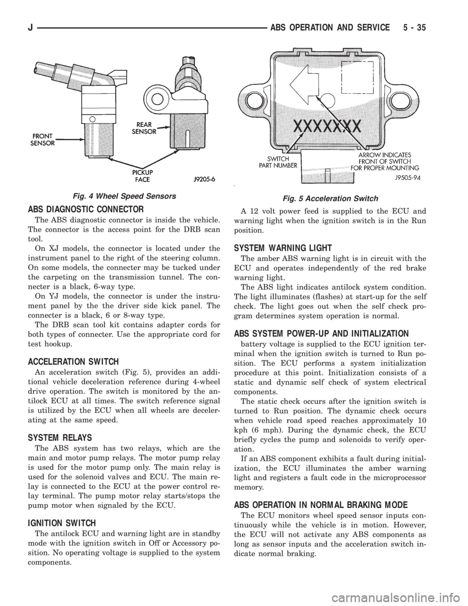
wheels (Fig. 4). The front/rear sensors have the same
electrical values but are not interchangeable.
Fig. 2 ABS Master Cylinder-Booster-Combination
Valve-HCU
Fig. 3 Antilock ECU
5 - 34 ABS OPERATION AND SERVICEJ
Page 172 of 2198
ABS DIAGNOSTIC CONNECTOR
The ABS diagnostic connector is inside the vehicle.
The connector is the access point for the DRB scan
tool.
On XJ models, the connector is located under the
instrument panel to the right of the steering column.
On some models, the connecter may be tucked under
the carpeting on the transmission tunnel. The con-
necter is a black, 6-way type.
On YJ models, the connector is under the instru-
ment panel by the the driver side kick panel. The
connecter is a black, 6 or 8-way type.
The DRB scan tool kit contains adapter cords for
both types of connecter. Use the appropriate cord for
test hookup.
ACCELERATION SWITCH
An acceleration switch (Fig. 5), provides an addi-
tional vehicle deceleration reference during 4-wheel
drive operation. The switch is monitored by the an-
tilock ECU at all times. The switch reference signal
is utilized by the ECU when all wheels are deceler-
ating at the same speed.
SYSTEM RELAYS
The ABS system has two relays, which are the
main and motor pump relays. The motor pump relay
is used for the motor pump only. The main relay is
used for the solenoid valves and ECU. The main re-
lay is connected to the ECU at the power control re-
lay terminal. The pump motor relay starts/stops the
pump motor when signaled by the ECU.
IGNITION SWITCH
The antilock ECU and warning light are in standby
mode with the ignition switch in Off or Accessory po-
sition. No operating voltage is supplied to the system
components.A 12 volt power feed is supplied to the ECU and
warning light when the ignition switch is in the Run
position.
SYSTEM WARNING LIGHT
The amber ABS warning light is in circuit with the
ECU and operates independently of the red brake
warning light.
The ABS light indicates antilock system condition.
The light illuminates (flashes) at start-up for the self
check. The light goes out when the self check pro-
gram determines system operation is normal.
ABS SYSTEM POWER-UP AND INITIALIZATION
battery voltage is supplied to the ECU ignition ter-
minal when the ignition switch is turned to Run po-
sition. The ECU performs a system initialization
procedure at this point. Initialization consists of a
static and dynamic self check of system electrical
components.
The static check occurs after the ignition switch is
turned to Run position. The dynamic check occurs
when vehicle road speed reaches approximately 10
kph (6 mph). During the dynamic check, the ECU
briefly cycles the pump and solenoids to verify oper-
ation.
If an ABS component exhibits a fault during initial-
ization, the ECU illuminates the amber warning
light and registers a fault code in the microprocessor
memory.
ABS OPERATION IN NORMAL BRAKING MODE
The ECU monitors wheel speed sensor inputs con-
tinuously while the vehicle is in motion. However,
the ECU will not activate any ABS components as
long as sensor inputs and the acceleration switch in-
dicate normal braking.
Fig. 4 Wheel Speed SensorsFig. 5 Acceleration Switch
JABS OPERATION AND SERVICE 5 - 35
Page 198 of 2198
secondary brakeshoes move the shoes directly into
contact with the drum braking surface. The actuating
levers are interconnected by a system of cables and a
tensioner mechanism. The tensioner mechanism con-
trols parking brake adjustment.
A parking brake switch is used on all models. It is
mounted on the parking brake lever or foot pedal and
is actuated by movement of the lever/pedal. The
switch, which is in circuit with the red warning light
in the dash, will illuminate the warning light when-
ever the parking brakes are applied.
On XJ models, the cable tensioner is part of the lever
assembly. On YJ models, the tensioner and equalizer
are mounted in a bracket attached to the underbody.
On YJ models, the parking brake front cable is at-
tached to the foot pedal and cable tensioner. The ten-
sioner and rear cables are connected to the equalizer
(Fig. 1).
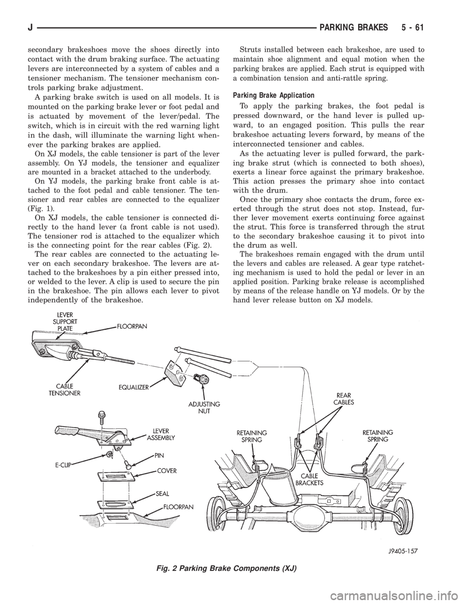
On XJ models, the cable tensioner is connected di-
rectly to the hand lever (a front cable is not used).
The tensioner rod is attached to the equalizer which
is the connecting point for the rear cables (Fig. 2).
The rear cables are connected to the actuating le-
ver on each secondary brakeshoe. The levers are at-
tached to the brakeshoes by a pin either pressed into,
or welded to the lever. A clip is used to secure the pin
in the brakeshoe. The pin allows each lever to pivot
independently of the brakeshoe.
Struts installed between each brakeshoe, are used to
maintain shoe alignment and equal motion when the
parking brakes are applied. Each strut is equipped with
a combination tension and anti-rattle spring.
Parking Brake Application
To apply the parking brakes, the foot pedal is
pressed downward, or the hand lever is pulled up-
ward, to an engaged position. This pulls the rear
brakeshoe actuating levers forward, by means of the
interconnected tensioner and cables.
As the actuating lever is pulled forward, the park-
ing brake strut (which is connected to both shoes),
exerts a linear force against the primary brakeshoe.
This action presses the primary shoe into contact
with the drum.
Once the primary shoe contacts the drum, force ex-
erted through the strut does not stop. Instead, fur-
ther lever movement exerts continuing force against
the strut. This force is transferred through the strut
to the secondary brakeshoe causing it to pivot into
the drum as well.
The brakeshoes remain engaged with the drum until
the levers and cables are released. A gear type ratchet-
ing mechanism is used to hold the pedal or lever in an
applied position. Parking brake release is accomplished
by means of the release handle on YJ models. Or by the
hand lever release button on XJ models.
Fig. 2 Parking Brake Components (XJ)
JPARKING BRAKES 5 - 61
Page 201 of 2198
(8) Remove shift handle by pulling upward sharply
on handle. Then remove shift bezel (Fig. 7).
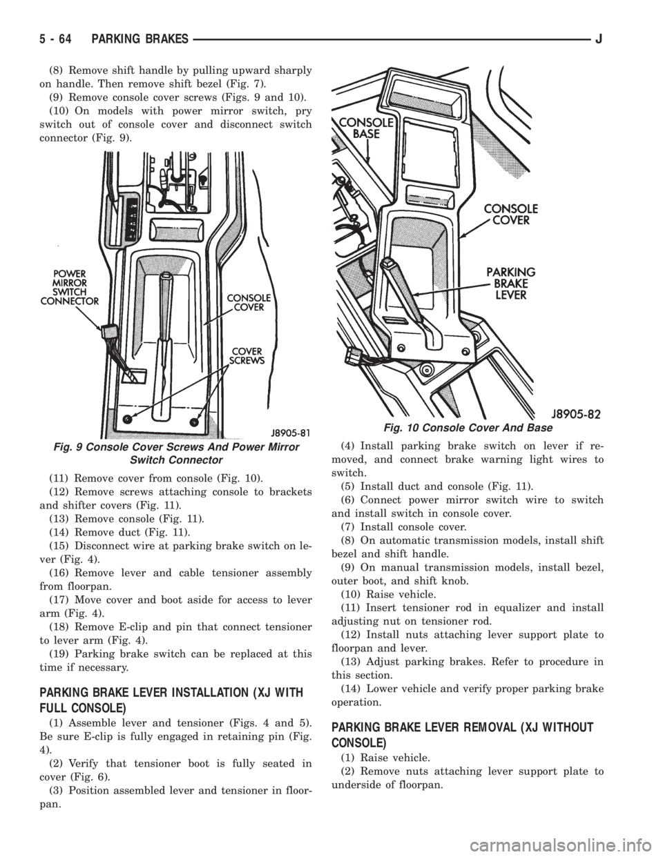
(9) Remove console cover screws (Figs. 9 and 10).
(10) On models with power mirror switch, pry
switch out of console cover and disconnect switch
connector (Fig. 9).
(11) Remove cover from console (Fig. 10).
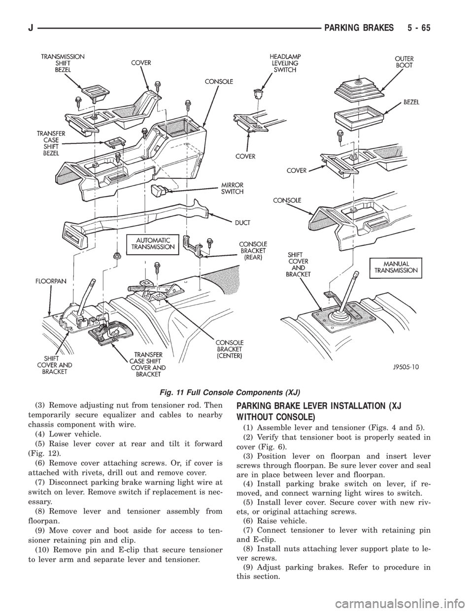
(12) Remove screws attaching console to brackets
and shifter covers (Fig. 11).
(13) Remove console (Fig. 11).
(14) Remove duct (Fig. 11).
(15) Disconnect wire at parking brake switch on le-
ver (Fig. 4).
(16) Remove lever and cable tensioner assembly
from floorpan.
(17) Move cover and boot aside for access to lever
arm (Fig. 4).
(18) Remove E-clip and pin that connect tensioner
to lever arm (Fig. 4).
(19) Parking brake switch can be replaced at this
time if necessary.
PARKING BRAKE LEVER INSTALLATION (XJ WITH
FULL CONSOLE)
(1) Assemble lever and tensioner (Figs. 4 and 5).
Be sure E-clip is fully engaged in retaining pin (Fig.
4).
(2) Verify that tensioner boot is fully seated in
cover (Fig. 6).
(3) Position assembled lever and tensioner in floor-
pan.(4) Install parking brake switch on lever if re-
moved, and connect brake warning light wires to
switch.
(5) Install duct and console (Fig. 11).
(6) Connect power mirror switch wire to switch
and install switch in console cover.
(7) Install console cover.
(8) On automatic transmission models, install shift
bezel and shift handle.
(9) On manual transmission models, install bezel,
outer boot, and shift knob.
(10) Raise vehicle.
(11) Insert tensioner rod in equalizer and install
adjusting nut on tensioner rod.
(12) Install nuts attaching lever support plate to
floorpan and lever.
(13) Adjust parking brakes. Refer to procedure in
this section.
(14) Lower vehicle and verify proper parking brake
operation.PARKING BRAKE LEVER REMOVAL (XJ WITHOUT
CONSOLE)
(1) Raise vehicle.
(2) Remove nuts attaching lever support plate to
underside of floorpan.
Fig. 9 Console Cover Screws And Power Mirror
Switch Connector
Fig. 10 Console Cover And Base
5 - 64 PARKING BRAKESJ
Page 202 of 2198
(3) Remove adjusting nut from tensioner rod. Then
temporarily secure equalizer and cables to nearby
chassis component with wire.
(4) Lower vehicle.
(5) Raise lever cover at rear and tilt it forward
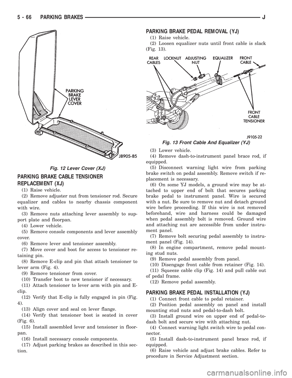
(Fig. 12).
(6) Remove cover attaching screws. Or, if cover is
attached with rivets, drill out and remove cover.
(7) Disconnect parking brake warning light wire at
switch on lever. Remove switch if replacement is nec-
essary.
(8) Remove lever and tensioner assembly from
floorpan.
(9) Move cover and boot aside for access to ten-
sioner retaining pin and clip.
(10) Remove pin and E-clip that secure tensioner
to lever arm and separate lever and tensioner.PARKING BRAKE LEVER INSTALLATION (XJ
WITHOUT CONSOLE)
(1) Assemble lever and tensioner (Figs. 4 and 5).
(2) Verify that tensioner boot is properly seated in
cover (Fig. 6).
(3) Position lever on floorpan and insert lever
screws through floorpan. Be sure lever cover and seal
are in place between lever and floorpan.
(4) Install parking brake switch on lever, if re-
moved, and connect warning light wires to switch.
(5) Install lever cover. Secure cover with new riv-
ets, or original attaching screws.
(6) Raise vehicle.
(7) Connect tensioner to lever with retaining pin
and E-clip.
(8) Install nuts attaching lever support plate to le-
ver screws.
(9) Adjust parking brakes. Refer to procedure in
this section.
Fig. 11 Full Console Components (XJ)
JPARKING BRAKES 5 - 65
Page 203 of 2198
PARKING BRAKE CABLE TENSIONER
REPLACEMENT (XJ)
(1) Raise vehicle.
(2) Remove adjuster nut from tensioner rod. Secure
equalizer and cables to nearby chassis component
with wire.
(3) Remove nuts attaching lever assembly to sup-
port plate and floorpan.
(4) Lower vehicle.
(5) Remove console components and lever assembly
cover.
(6) Remove lever and tensioner assembly.
(7) Move cover and boot for access to tensioner re-
taining pin.
(8) Remove E-clip and pin that attach tensioner to
lever arm (Fig. 4).
(9) Remove tensioner from cover.
(10) Transfer boot to new tensioner if necessary.
(11) Attach tensioner to lever arm with pin and E-
clip.
(12) Verify that E-clip is fully engaged in pin (Fig.
4).
(13) Align cover and seal on lever flange.
(14) Verify that tensioner boot is seated in cover
(Fig. 6).
(15) Install assembled lever and tensioner in floor-
pan.
(16) Install necessary console components.
(17) Adjust parking brakes as described in this sec-
tion.
PARKING BRAKE PEDAL REMOVAL (YJ)
(1) Raise vehicle.
(2) Loosen equalizer nuts until front cable is slack
(Fig. 13).
(3) Lower vehicle.
(4) Remove dash-to-instrument panel brace rod, if
equipped.
(5) Disconnect warning light wire from parking
brake switch on pedal assembly. Remove switch if re-
placement is necessary.
(6) On some YJ models, a ground wire may be at-
tached to upper end of bolt that secures parking
brake pedal to instrument panel. Wire is secured
with a nut. Be sure to remove nut and detach ground
wire before proceeding. If this wire is not removed
beforehand, wire and harness could be damaged
when pedal assembly bolt is removed. Ground wire
and attaching nut are accessible from under instru-
ment panel.
(7) Remove bolt securing pedal assembly to instru-
ment panel (Fig. 14).
(8) In engine compartment, remove pedal mount-
ing stud nuts.
(9) Remove pedal assembly from panel.
(10) Disengage front cable from retainer (Fig. 14).
(11) Squeeze cable clip (Fig. 14) and pull cable out
of pedal frame.
(12) Remove pedal assembly.
PARKING BRAKE PEDAL INSTALLATION (YJ)
(1) Connect front cable to pedal retainer.
(2) Position pedal assembly on panel and install
mounting stud nuts and pedal-to-dash bolt.
(3) Install ground wire on upper end of pedal-to-
dash bolt and secure wire with attaching nut.
(4) Connect warning light switch wire to pedal con-
nector.
(5) Install dash-to-instrument panel brace rod, if
equipped.
(6) Raise vehicle and adjust brake cables. Refer to
procedure in Service Adjustment section.
Fig. 12 Lever Cover (XJ)
Fig. 13 Front Cable And Equalizer (YJ)
5 - 66 PARKING BRAKESJ
Page 217 of 2198
CLUTCH SERVICE
INDEX
page page
Clutch Component Lubrication................ 10
Clutch Cover and Disc Installation............. 10
Clutch Cover and Disc Removal.............. 10
Clutch Fluid Level......................... 14
Clutch Housing Replacement................ 13
Clutch Hydraulic Linkage Installation........... 14
Clutch Hydraulic Linkage Removal............. 13Clutch Pedal Installation.................... 15
Clutch Pedal Removal...................... 15
Clutch Safety Precautions................... 10
Flywheel Service.......................... 16
Pilot Bearing Replacement.................. 12
Release Bearing Replacement................ 11
CLUTCH SAFETY PRECAUTIONS
WARNING: EXERCISE CARE WHEN SERVICING
CLUTCH COMPONENTS. DUST AND DIRT ON
CLUTCH PARTS USE MAY CONTAIN ASBESTOS FI-
BERS. BREATHING EXCESSIVE CONCENTRATIONS
OF THESE FIBERS CAN CAUSE SERIOUS BODILY
HARM. WEAR A RESPIRATOR DURING SERVICE
AND NEVER CLEAN CLUTCH COMPONENTS WITH
COMPRESSED AIR OR WITH A DRY BRUSH. EI-
THER CLEAN THE COMPONENTS WITH A WATER
DAMPENED RAGS OR USE A VACUUM CLEANER
SPECIFICALLY DESIGNED FOR REMOVING ASBES-
TOS FIBERS AND DUST. DO NOT CREATE DUST BY
SANDING A CLUTCH DISC. REPLACE THE DISC IF
THE FRICTION MATERIAL IS DAMAGED OR CON-
TAMINATED. DISPOSE OF ALL DUST AND DIRT
CONTAINING ASBESTOS FIBERS IN SEALED BAGS
OR CONTAINERS. THIS WILL HELP MINIMIZE EX-
POSURE TO YOURSELF AND TO OTHERS. FOL-
LOW ALL RECOMMENDED SAFETY PRACTICES
PRESCRIBED BY THE OCCUPATIONAL SAFETY
AND HEALTH ADMINISTRATION (OSHA) AND THE
ENVIRONMENTAL SAFETY AGENCY (EPA), FOR
THE HANDLING AND DISPOSAL OF PRODUCTS
CONTAINING ASBESTOS.
CLUTCH COMPONENT LUBRICATION
Proper clutch component lubrication is important
to satisfactory operation. Using the correct lubricant
and not overlubricating are equally important. Apply
recommended lubricant sparingly to avoid disc and
pressure plate contamination.
Clutch and transmission components requiring lu-
brication are:
²pilot bearing
²release lever pivot ball stud
²release lever contact surfaces
²release bearing bore
²clutch disc hub splines
²clutch pedal pivot shaft bore
²clutch pedal bushings²input shaft splines
²input shaft pilot hub
²transmission front bearing retainer slide surface
Never apply grease to any part of the clutch
cover, or disc.
Recommended Lubricants
Use Mopar multi-purpose grease for the clutch
pedal bushings and pivot shaft. Use Mopar high tem-
perature grease (or equivalent) for all other lubrica-
tion requirements. Apply recommended amounts and
do not overlubricate.
CLUTCH COVER AND DISC REMOVAL
(1) Remove transmission. Refer to procedures in
Group 21.
(2) If original clutch cover will be reinstalled, mark
position of cover on flywheel for assembly reference.
Use paint or a scriber for this purpose.
(3) If clutch cover is to be replaced, cover bolts can
be removed in any sequence. However, if original
cover will be reinstalled, loosen cover bolts evenly
and in rotation to relieve spring tension equally. This
is necessary avoid warping cover.
(4) Remove cover bolts and remove cover and disc
(Fig. 2).
CLUTCH COVER AND DISC INSTALLATION
(1) Lightly scuff sand flywheel face with 180 grit
emery cloth. Then clean surface with a wax and
grease remover.
(2) Lubricate pilot bearing with Mopar high tem-
perature bearing grease.
(3) Check runout and free operation of new clutch
disc as follows:
(a) Slide disc onto transmission input shaft
splines. Disc should slide freely on splines.
(b) Leave disc on shaft and check face runout
with dial indicator. Check runout at disc hub and
about 6 mm (1/4 in.) from outer edge of facing.
(c) Face runout should not exceed 0.5 mm (0.020
in.). Obtain another clutch disc if runout exceeds
this limit.
6 - 10 CLUTCH SERVICEJ