Page 506 of 2198
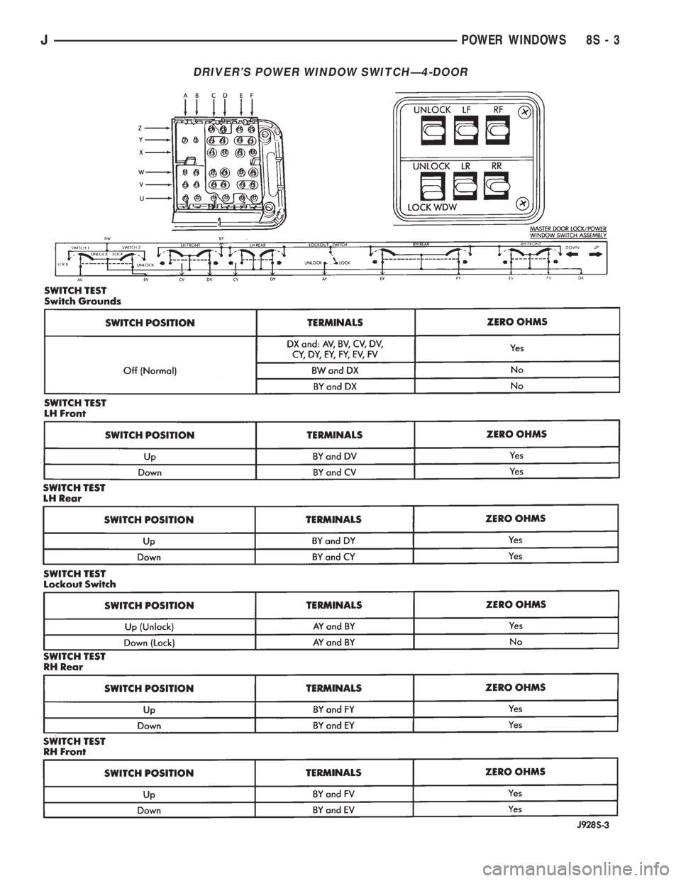
DRIVER'S POWER WINDOW SWITCHÐ4-DOOR
JPOWER WINDOWS 8S - 3
Page 507 of 2198
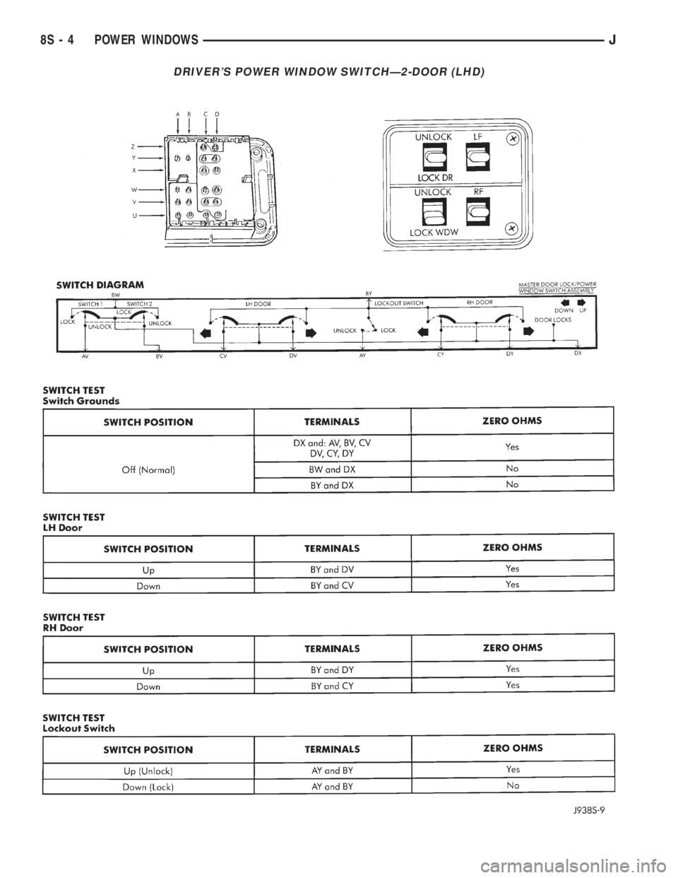
DRIVER'S POWER WINDOW SWITCHÐ2-DOOR (LHD)
8S - 4 POWER WINDOWSJ
Page 508 of 2198
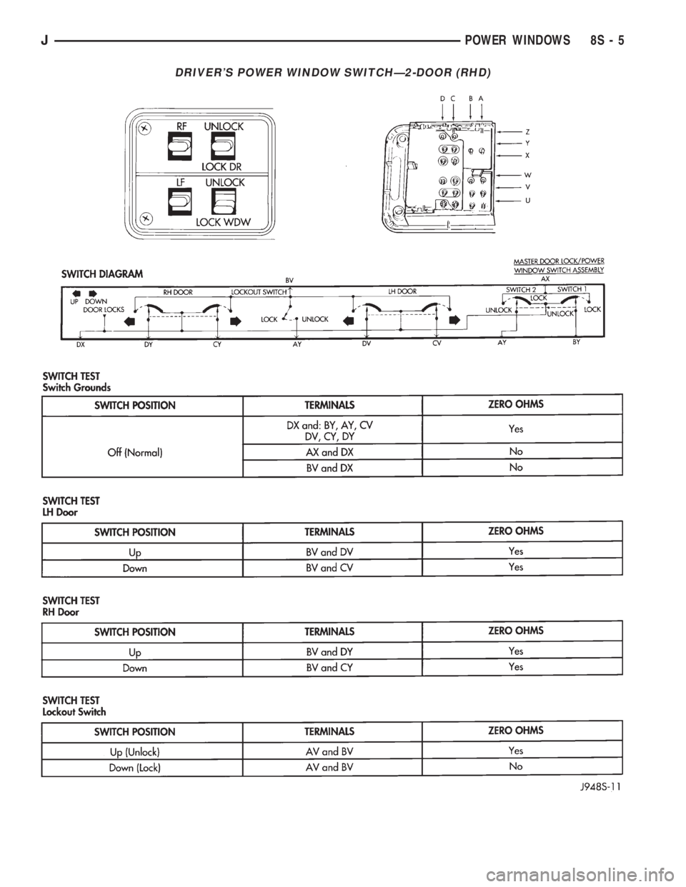
DRIVER'S POWER WINDOW SWITCHÐ2-DOOR (RHD)
JPOWER WINDOWS 8S - 5
Page 509 of 2198
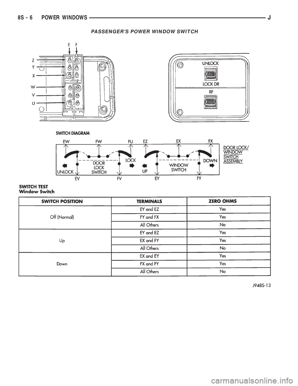
PASSENGER'S POWER WINDOW SWITCH
8S - 6 POWER WINDOWSJ
Page 510 of 2198
SERVICE PROCEDURES
POWER WINDOW SWITCH REMOVE/INSTALL
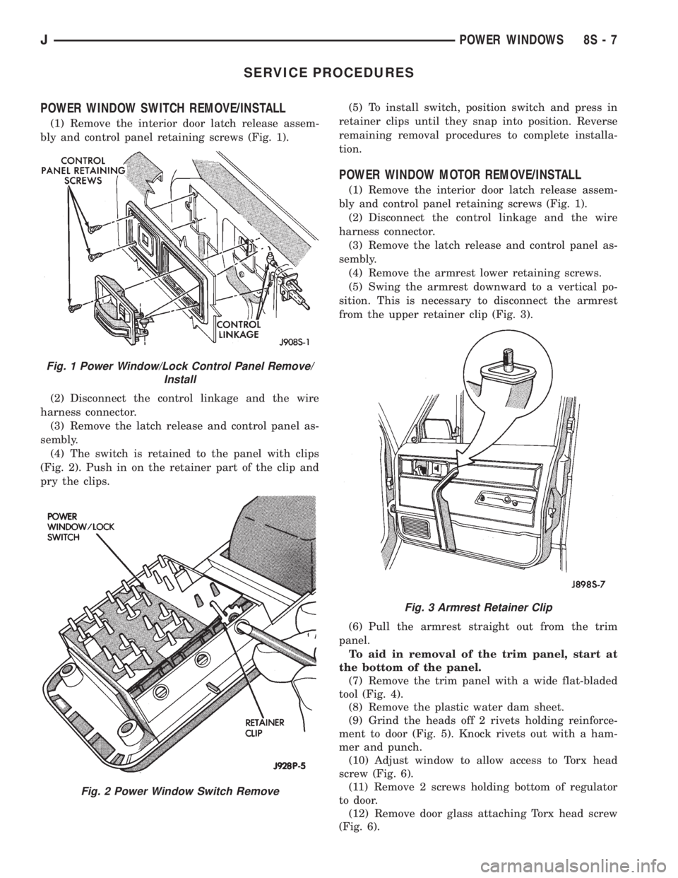
(1) Remove the interior door latch release assem-
bly and control panel retaining screws (Fig. 1).
(2) Disconnect the control linkage and the wire
harness connector.
(3) Remove the latch release and control panel as-
sembly.
(4) The switch is retained to the panel with clips
(Fig. 2). Push in on the retainer part of the clip and
pry the clips.(5) To install switch, position switch and press in
retainer clips until they snap into position. Reverse
remaining removal procedures to complete installa-
tion.
POWER WINDOW MOTOR REMOVE/INSTALL
(1) Remove the interior door latch release assem-
bly and control panel retaining screws (Fig. 1).
(2) Disconnect the control linkage and the wire
harness connector.
(3) Remove the latch release and control panel as-
sembly.
(4) Remove the armrest lower retaining screws.
(5) Swing the armrest downward to a vertical po-
sition. This is necessary to disconnect the armrest
from the upper retainer clip (Fig. 3).
(6) Pull the armrest straight out from the trim
panel.
To aid in removal of the trim panel, start at
the bottom of the panel.
(7) Remove the trim panel with a wide flat-bladed
tool (Fig. 4).
(8) Remove the plastic water dam sheet.
(9) Grind the heads off 2 rivets holding reinforce-
ment to door (Fig. 5). Knock rivets out with a ham-
mer and punch.
(10) Adjust window to allow access to Torx head
screw (Fig. 6).
(11) Remove 2 screws holding bottom of regulator
to door.
(12) Remove door glass attaching Torx head screw
(Fig. 6).
Fig. 1 Power Window/Lock Control Panel Remove/
Install
Fig. 2 Power Window Switch Remove
Fig. 3 Armrest Retainer Clip
JPOWER WINDOWS 8S - 7
Page 511 of 2198
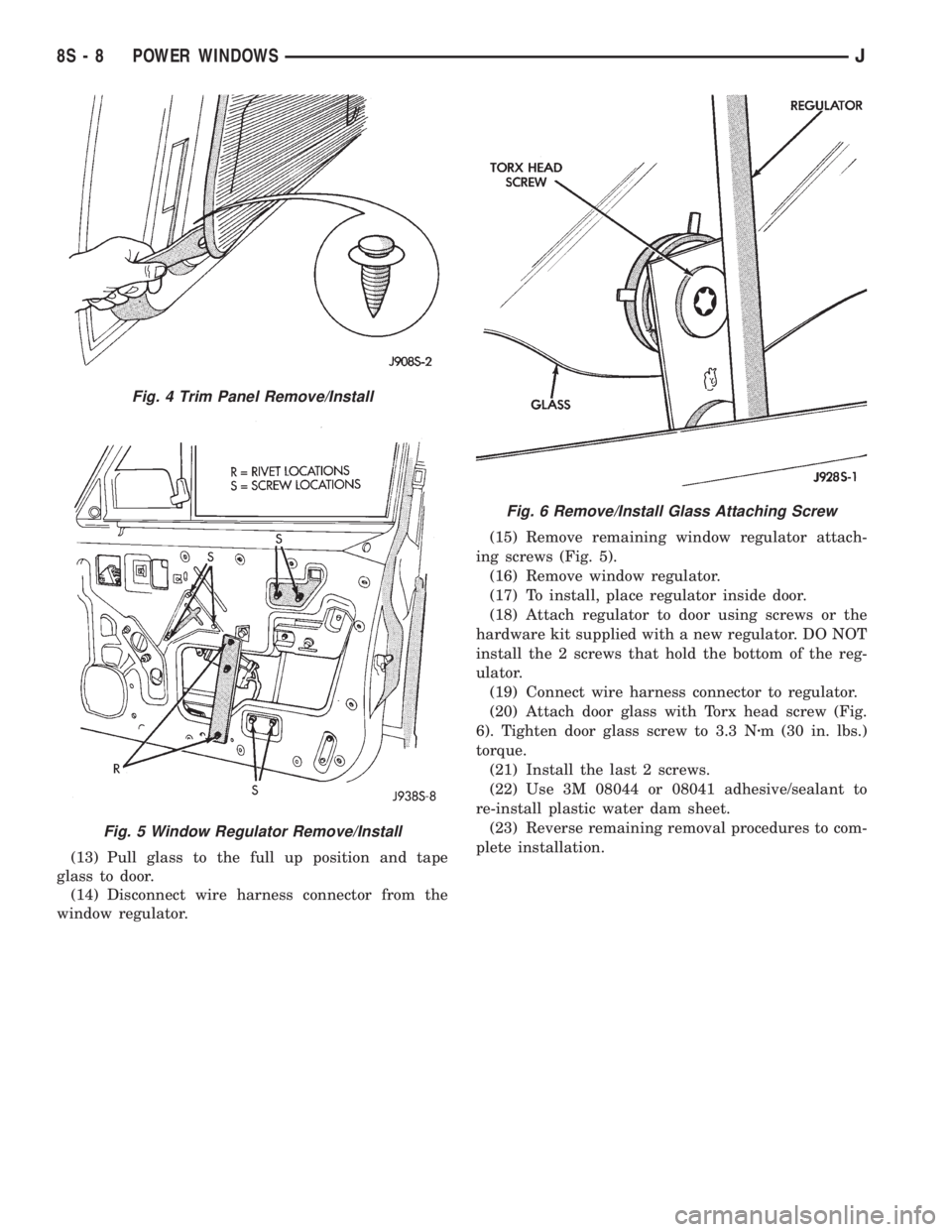
(13) Pull glass to the full up position and tape
glass to door.
(14) Disconnect wire harness connector from the
window regulator.(15) Remove remaining window regulator attach-
ing screws (Fig. 5).
(16) Remove window regulator.
(17) To install, place regulator inside door.
(18) Attach regulator to door using screws or the
hardware kit supplied with a new regulator. DO NOT
install the 2 screws that hold the bottom of the reg-
ulator.
(19) Connect wire harness connector to regulator.
(20) Attach door glass with Torx head screw (Fig.
6). Tighten door glass screw to 3.3 Nzm (30 in. lbs.)
torque.
(21) Install the last 2 screws.
(22) Use 3M 08044 or 08041 adhesive/sealant to
re-install plastic water dam sheet.
(23) Reverse remaining removal procedures to com-
plete installation.
Fig. 4 Trim Panel Remove/Install
Fig. 5 Window Regulator Remove/Install
Fig. 6 Remove/Install Glass Attaching Screw
8S - 8 POWER WINDOWSJ
Page 530 of 2198
WIRING DIAGRAMS
CONTENTS
page page
8W-01 GENERAL INFORMATIONÐWIRING
DIAGRAMS.................... 8W-01-1
8W-10 FUSE/FUSE BLOCK........... 8W-10-1
8W-11 POWER DISTRIBUTION........ 8W-11-1
8W-15 GROUND DISTRIBUTION....... 8W-15-1
8W-20 CHARGING SYSTEM.......... 8W-20-1
8W-21 STARTING SYSTEM........... 8W-21-1
8W-30 FUEL/IGNITION.............. 8W-30-1
8W-31 TRANSMISSION CONTROLS.... 8W-31-1
8W-32 ANTI-LOCK BRAKES.......... 8W-32-1
8W-33 VEHICLE SPEED CONTROL..... 8W-33-1
8W-40 INSTRUMENT CLUSTER....... 8W-40-1
8W-41 HORN/CIGAR LIGHTER......... 8W-41-1
8W-42 AIR CONDITIONING/HEATER.... 8W-42-1
8W-44 INTERIOR LIGHTING.......... 8W-44-1
8W-47 AUDIO SYSTEM.............. 8W-47-18W-48 HEATED REAR WINDOW....... 8W-48-1
8W-49 OVERHEAD CONSOLE......... 8W-49-1
8W-50 FRONT LIGHTING............. 8W-50-1
8W-51 REAR LIGHTING............. 8W-51-1
8W-52 TURN SIGNALS.............. 8W-52-1
8W-53 WIPERS..................... 8W-53-1
8W-54 TRAILER TOW................ 8W-54-1
8W-60 POWER WINDOWS.......... 8W-60-1
8W-61 POWER DOOR LOCKS......... 8W-61-1
8W-62 POWER MIRRORS............ 8W-62-1
8W-63 POWER SEAT................ 8W-63-1
8W-70 SPLICE INFORMATION........ 8W-70-1
8W-80 CONNECTOR PIN OUTS....... 8W-80-1
8W-90 CONNECTOR LOCATIONS...... 8W-90-1
8W-95 SPLICE LOCATIONS........... 8W-95-1
HOW TO USE THIS GROUP
The purpose of this group is to show the electrical
circuits in a clear, simple fashion and to make trou-
bleshooting easier. Components that work together
are shown together. All electrical components used in
a specific system are shown on one diagram. The feed
for a system is shown at the top of the page. All
wires, connectors, splices, and components are shown
in the flow of current to the bottom of the page. Wir-
ing which is not part of the circuit represented is ref-
erenced to another page/section, where the complete
circuit is shown. In addition, all switches, compo-
nents, and modules are shown in theat rest posi-
tion with the doors closed and the key removed
from the ignition.
If a component is part of several different circuits,
it is shown in the diagram for each. For example, the
headlamp switch is the main part of the exterior
lighting, but it also affects the interior lighting and
the chime warning system.
It is important to realize that no attempt is
made on the diagrams to represent components
and wiring as they appear on the vehicle. For
example, a short piece of wire is treated the
same as a long one. In addition, switches and
other components are shown as simply as pos-
sible, with regard to function only.
The wiring diagram show circuits for all wheel-
bases. If there is a difference in systems or compo-
nents between wheel-bases, an identifier is placed
next to the component.
SECTION IDENTIFICATION
Sections in Group 8W are organized by sub-sys-
tems. The sections contain circuit operation descrip-
tions, helpful information, and system diagrams. The
intention is to organize information by system, con-
sistently from year to year.
CONNECTOR LOCATIONS
Section 8W-90 contains Connector Location illus-
trations. The illustrations contain the connector
number and component identification. Connector Lo-
cation charts in Section 8W-90 reference the illustra-
tion number for components and connectors.
Section 8W-80 shows each connector and the cir-
cuits involved with that connector. The connectors
are identified using the number on the Diagram
pages.
SPLICE LOCATIONS
Splice Location charts in Section 8W-70 show the
entire splice, and provide references to other sections
the splice serves.
Section 8W-95 contains illustrations that show the
general location of the splices in each harness. The
illustrations show the splice by number, and provide
a written location.
JWIRING DIAGRAMSÐXJ VEHICLES 8W - 1 - 1
Page 532 of 2198
FUSE/FUSE BLOCK
GENERAL INFORMATION
This section covers the Fuse Block and all circuits
involved with it. For additional information on sys-
tem operation, refer to the appropriate section of the
wiring diagrams.
DIAGRAM INDEX
Component Page
ABS Control Module......................8W-10-4
ABS Warning Lamp Relay...................8W-10-2
Chime/Buzzer Module.................8W-10-2, 9, 10
Circuit Breaker Cavity 16...................8W-10-12
In-Line Circuit Breaker (Wipers)...............8W-10-5
In-Line Circuit Breaker (Stop Lamp Relay)........8W-10-12
Daytime Running Lamps Module..............8W-10-8
Fuse 1 (Fuse Block).......................8W-10-4
Fuse 2 (Fuse Block).......................8W-10-5
Fuse 3 (Fuse Block).....................8W-10-4, 8
Fuse 3 (PDC)........................8W-10-6, 12
Fuse 4 (Fuse Block).......................8W-10-7
Fuse 5 (Fuse Block).......................8W-10-5
Fuse 5 (PDC)........................8W-10-7, 10
Fuse 6 (Fuse Block).......................8W-10-4
Fuse 6 (PDC).........................8W-10-4, 8
Fuse 7 (Fuse Block)....................8W-10-4, 10
Fuse 8 (Fuse Block).......................8W-10-5
Fuse 9 (Fuse Block).......................8W-10-6
Fuse 10 (Fuse Block)......................8W-10-4
Fuse 11 (Fuse Block)......................8W-10-9
Fuse 11 (PDC)..........................8W-10-8
Fuse 12 (PDC)..........................8W-10-8
Fuse 13 (Fuse Block)......................8W-10-9
Fuse 14 (Fuse Block)......................8W-10-9
Fuse 15 (Fuse Block)......................8W-10-7
Fuse 15 (PDC)..........................8W-10-6
Fuse 17 (Fuse Block)......................8W-10-9
Fuse Block.............................8W-10-2
Headlamp Delay Module....................8W-10-9
Headlamp Switch......................8W-10-7, 10
Heated Rear Window Relay.................8W-10-10
Ignition Switch........................8W-10-4, 8
Instrument Cluster.......................8W-10-11
Overhead Console.....................8W-10-9, 11
Powertrain Control Module..................8W-10-8
Remote Keyless Entry Module................8W-10-9
J8W-10 FUSE/FUSE BLOCKÐXJ VEHICLES 8W - 10 - 1