1995 JEEP CHEROKEE Power window
[x] Cancel search: Power windowPage 272 of 2198

ELECTRICAL
GROUP INDEX
Group Group
AUDIO SYSTEMS........................ 8F
BATTERY/STARTER/GENERATOR SERVICE.... 8B
BATTERY/STARTING/CHARGING SYSTEMS
DIAGNOSTICS......................... 8A
CHIME/BUZZER WARNING SYSTEMS........ 8U
HORNS................................ 8G
IGNITION SYSTEMS...................... 8D
INSTRUMENT PANEL AND GAUGES......... 8E
LAMPS................................ 8L
OVERHEAD CONSOLE.................... 8C
POWER LOCKS.......................... 8P
POWER MIRRORS....................... 8TPOWER SEATS.......................... 8R
POWER WINDOWS....................... 8S
REAR WINDOW DEFOGGER............... 8N
RESTRAINT SYSTEMS................... 8M
TURN SIGNAL AND HAZARD WARNING
SYSTEMS............................. 8J
VEHICLE SPEED CONTROL SYSTEM......... 8H
WIPER AND WASHER SYSTEMS............ 8K
XJ WIRING DIAGRAMS-LEFT HAND DRIVE . . . 8W
XJ WIRING DIAGRAMS-RIGHT HAND DRIVE . 8W
YJ WIRING DIAGRAMS.................. 8W
BATTERY/STARTING/CHARGING SYSTEMS DIAGNOSTICS
CONTENTS
page page
BATTERY............................... 2
CHARGING SYSTEM..................... 17
IGNITION-OFF DRAW.................... 10SPECIFICATIONS........................ 23
STARTING SYSTEM...................... 11
USING ON-BOARD DIAGNOSTIC SYSTEM.... 22
GENERAL INFORMATION
The battery, starting, and charging systems operate
with one another; therefore, they must be tested as a
complete system. In order for the vehicle to start and
charge properly, all of the components involved in
these systems must perform within specifications.
Group 8A covers battery, starting (Fig. 1) and
charging (Fig. 2) system diagnostic procedures. These
procedures include the most basic conventional diag-
nostic methods, to On-Board Diagnostics (OBD) builtinto the Powertrain Control Module (PCM). Use of an
induction milliamp ammeter, volt/ohmmeter, battery
charger, carbon pile rheostat (load tester), and 12-
volt test lamp will be required.
All OBD-sensed systems are monitored by the
PCM. Each monitored circuit is assigned a Diagnos-
tic Trouble Code (DTC). The PCM will store a DTC in
electronic memory for any failure it detects. See Us-
ing On-Board Diagnostic System in this group for
more information.
JELECTRICAL 8A - 1
Page 400 of 2198
SERVICE PROCEDURES
HORN REMOVE/INSTALL
XJ
(1) Raise and support the vehicle.
(2) Remove the front underbody splash shield.
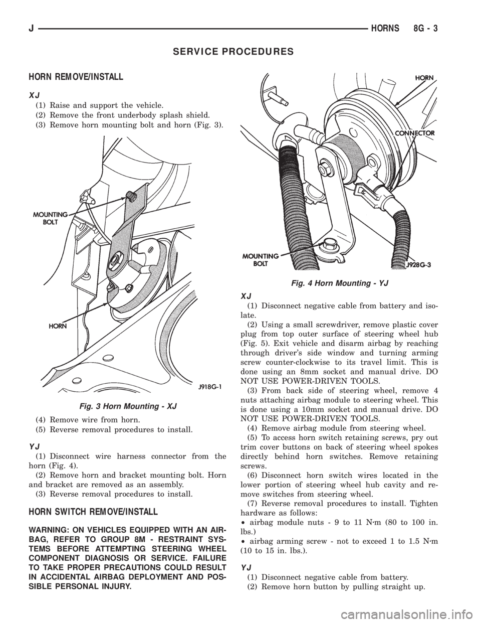
(3) Remove horn mounting bolt and horn (Fig. 3).
(4) Remove wire from horn.
(5) Reverse removal procedures to install.
YJ
(1) Disconnect wire harness connector from the
horn (Fig. 4).
(2) Remove horn and bracket mounting bolt. Horn
and bracket are removed as an assembly.
(3) Reverse removal procedures to install.
HORN SWITCH REMOVE/INSTALL
WARNING: ON VEHICLES EQUIPPED WITH AN AIR-
BAG, REFER TO GROUP 8M - RESTRAINT SYS-
TEMS BEFORE ATTEMPTING STEERING WHEEL
COMPONENT DIAGNOSIS OR SERVICE. FAILURE
TO TAKE PROPER PRECAUTIONS COULD RESULT
IN ACCIDENTAL AIRBAG DEPLOYMENT AND POS-
SIBLE PERSONAL INJURY.
XJ
(1) Disconnect negative cable from battery and iso-
late.
(2) Using a small screwdriver, remove plastic cover
plug from top outer surface of steering wheel hub
(Fig. 5). Exit vehicle and disarm airbag by reaching
through driver's side window and turning arming
screw counter-clockwise to its travel limit. This is
done using an 8mm socket and manual drive. DO
NOT USE POWER-DRIVEN TOOLS.
(3) From back side of steering wheel, remove 4
nuts attaching airbag module to steering wheel. This
is done using a 10mm socket and manual drive. DO
NOT USE POWER-DRIVEN TOOLS.
(4) Remove airbag module from steering wheel.
(5) To access horn switch retaining screws, pry out
trim cover buttons on back of steering wheel spokes
directly behind horn switches. Remove retaining
screws.
(6) Disconnect horn switch wires located in the
lower portion of steering wheel hub cavity and re-
move switches from steering wheel.
(7) Reverse removal procedures to install. Tighten
hardware as follows:
²airbag module nuts-9to11Nzm (80 to 100 in.
lbs.)
²airbag arming screw - not to exceed 1 to 1.5 Nzm
(10 to 15 in. lbs.).
YJ
(1) Disconnect negative cable from battery.
(2) Remove horn button by pulling straight up.
Fig. 3 Horn Mounting - XJ
Fig. 4 Horn Mounting - YJ
JHORNS 8G - 3
Page 482 of 2198
DEPLOYED
Following an airbag deployment, the vehicle inte-
rior will contain a powdery residue. This residue is
primarily sodium bicarbonate (baking soda), used as
an airbag cushion lubricant. However, there will also
be traces of sodium hydroxide powder, a chemical
byproduct of the generant used for airbag deploy-
ment. Since this powder can irritate the skin, eyes,
nose or throat, be sure to wear safety glasses, rubber
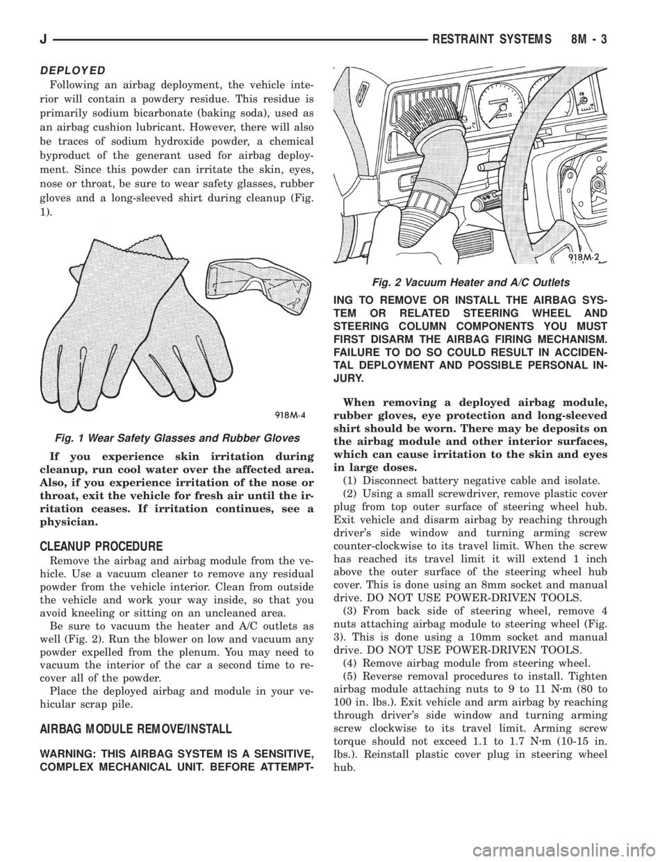
gloves and a long-sleeved shirt during cleanup (Fig.
1).
If you experience skin irritation during
cleanup, run cool water over the affected area.
Also, if you experience irritation of the nose or
throat, exit the vehicle for fresh air until the ir-
ritation ceases. If irritation continues, see a
physician.
CLEANUP PROCEDURE
Remove the airbag and airbag module from the ve-
hicle. Use a vacuum cleaner to remove any residual
powder from the vehicle interior. Clean from outside
the vehicle and work your way inside, so that you
avoid kneeling or sitting on an uncleaned area.
Be sure to vacuum the heater and A/C outlets as
well (Fig. 2). Run the blower on low and vacuum any
powder expelled from the plenum. You may need to
vacuum the interior of the car a second time to re-
cover all of the powder.
Place the deployed airbag and module in your ve-
hicular scrap pile.
AIRBAG MODULE REMOVE/INSTALL
WARNING: THIS AIRBAG SYSTEM IS A SENSITIVE,
COMPLEX MECHANICAL UNIT. BEFORE ATTEMPT-ING TO REMOVE OR INSTALL THE AIRBAG SYS-
TEM OR RELATED STEERING WHEEL AND
STEERING COLUMN COMPONENTS YOU MUST
FIRST DISARM THE AIRBAG FIRING MECHANISM.
FAILURE TO DO SO COULD RESULT IN ACCIDEN-
TAL DEPLOYMENT AND POSSIBLE PERSONAL IN-
JURY.
When removing a deployed airbag module,
rubber gloves, eye protection and long-sleeved
shirt should be worn. There may be deposits on
the airbag module and other interior surfaces,
which can cause irritation to the skin and eyes
in large doses.
(1) Disconnect battery negative cable and isolate.
(2) Using a small screwdriver, remove plastic cover
plug from top outer surface of steering wheel hub.
Exit vehicle and disarm airbag by reaching through
driver's side window and turning arming screw
counter-clockwise to its travel limit. When the screw
has reached its travel limit it will extend 1 inch
above the outer surface of the steering wheel hub
cover. This is done using an 8mm socket and manual
drive. DO NOT USE POWER-DRIVEN TOOLS.
(3) From back side of steering wheel, remove 4
nuts attaching airbag module to steering wheel (Fig.
3). This is done using a 10mm socket and manual
drive. DO NOT USE POWER-DRIVEN TOOLS.
(4) Remove airbag module from steering wheel.
(5) Reverse removal procedures to install. Tighten
airbag module attaching nuts to 9 to 11 Nzm (80 to
100 in. lbs.). Exit vehicle and arm airbag by reaching
through driver's side window and turning arming
screw clockwise to its travel limit. Arming screw
torque should not exceed 1.1 to 1.7 Nzm (10-15 in.
lbs.). Reinstall plastic cover plug in steering wheel
hub.
Fig. 1 Wear Safety Glasses and Rubber Gloves
Fig. 2 Vacuum Heater and A/C Outlets
JRESTRAINT SYSTEMS 8M - 3
Page 485 of 2198
nal B (driver side) with the positive lead. The volt-
meter should read 10-14 volts.
Steps 3, 4 or 5 above will confirm system operation.
Indicator light illumination means that there is
power available at the output of the switch, but does
not confirm that power is reaching the rear window
grid lines.
If the rear window defogger does not operate, the
problem should be isolated in the following manner:
(1) Confirm that ignition switch is in ON position.
(2) Ensure that the heated rear window feed and
ground wires are connected to the glass. Confirm
that the ground wire has continuity to ground.
(3) Check fuses 8 and 18 (XJ), or fuses 6 and 9
(YJ) in fuseblock module. Fuses must be tight in
their receptacles and all electrical connections must
be secure.
When the above steps have been completed and the
system is still inoperative, one or more of the follow-
ing is faulty:
²defogger switch²relay/timer
²rear window grid lines (all grid lines would have
to be broken or one of the feed wires disconnected for
the entire system to be inoperative).
If turning the switch ON produces severe voltmeter
deflection, check for a short circuit.
REAR WINDOW GLASS GRID
To detect breaks in grid lines, the following proce-
dure is required:
(1) Turn ignition switch to the ON position. Turn
rear defogger switch ON. The indicator lamp should
light.
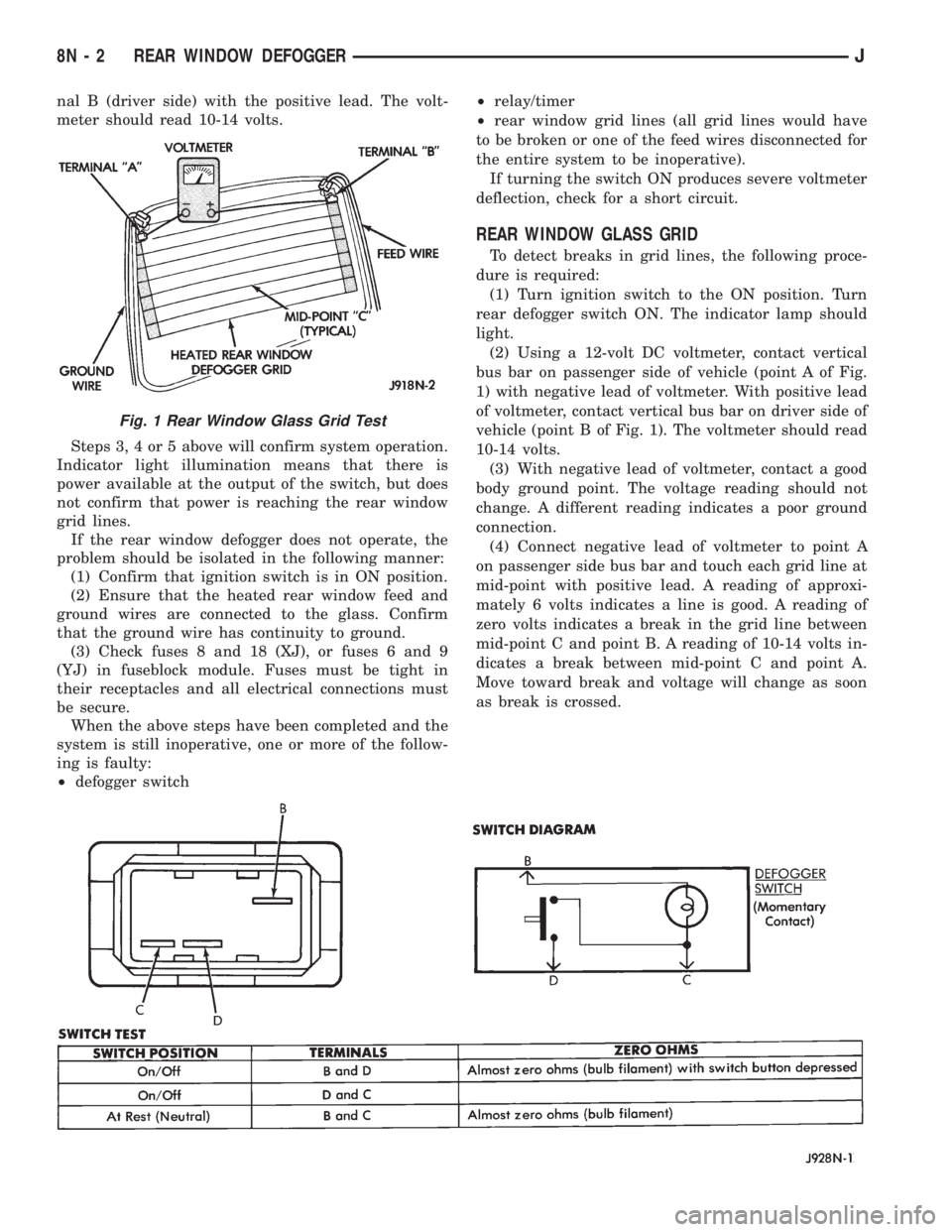
(2) Using a 12-volt DC voltmeter, contact vertical
bus bar on passenger side of vehicle (point A of Fig.
1) with negative lead of voltmeter. With positive lead
of voltmeter, contact vertical bus bar on driver side of
vehicle (point B of Fig. 1). The voltmeter should read
10-14 volts.
(3) With negative lead of voltmeter, contact a good
body ground point. The voltage reading should not
change. A different reading indicates a poor ground
connection.
(4) Connect negative lead of voltmeter to point A
on passenger side bus bar and touch each grid line at
mid-point with positive lead. A reading of approxi-
mately 6 volts indicates a line is good. A reading of
zero volts indicates a break in the grid line between
mid-point C and point B. A reading of 10-14 volts in-
dicates a break between mid-point C and point A.
Move toward break and voltage will change as soon
as break is crossed.
Fig. 1 Rear Window Glass Grid Test
8N - 2 REAR WINDOW DEFOGGERJ
Page 488 of 2198
POWER LOCKS
CONTENTS
page page
DIAGNOSIS............................. 2
GENERAL INFORMATION.................. 1SERVICE PROCEDURES................... 8
GENERAL INFORMATION
Power locks are optional equipment on XJ (Chero-
kee) models. Power windows and the keyless entry
system are included on vehicles equipped with the
power lock option. All doors and the liftgate can be
locked and unlocked electrically by operating the
switch on either front door panel, or by operating the
lock and unlock buttons of the remote keyless entry
transmitter. The power lock and keyless entry sys-
tems operate with battery power supplied indepen-
dent of the ignition switch.
Following are general descriptions of the major
components in the power lock system. Refer to Group
8W - Wiring Diagrams for complete circuit descrip-
tions and diagrams. Refer to the owner's manual for
more information on the features and use of these
systems.
POWER LOCK SWITCH
The power locks are controlled by a two-way switch
mounted on the trim panel of each front door. The
switch controls battery feed to the lock and unlock
relays. The door lock switches can not be repaired. If
faulty, the entire switch must be replaced.
POWER LOCK/UNLOCK RELAYS
The power lock and unlock relays are located in the
relay center. The relay center is located on the lower
instrument panel reinforcement behind the lower in-
strument panel and just right of the steering column.
The relays respond to inputs from the power lock
switches and the keyless entry module by sending
the correct battery and ground feeds to the lock mo-
tors. The lock and unlock relays can not be repaired.
If faulty, they must be replaced.
POWER LOCK MOTOR
The locks are actuated by a reversible motor
mounted within each door. The motor direction iscontrolled by the battery and ground feeds from the
power lock/unlock relays. The motor can not be re-
paired. If faulty, the entire motor must be replaced.
KEYLESS ENTRY TRANSMITTER
The keyless entry transmitter is equipped with two
buttons labeled Lock and Unlock. It is also designed
to serve as a key fob and is equipped with a key ring.
Each transmitter has a different vehicle access code,
which must be programmed into the memory of the
keyless entry module in the vehicle in order to oper-
ate the locks. The operating range of the infrared
transmitter signal is up to 4.75 meters (15 feet) from
the receiver.
The transmitter operates on two CR1616 3-volt (or
equivalent) batteries. Typical battery life is from one
to two years.
KEYLESS ENTRY MODULE
The keyless entry module is mounted in a housing
on the headliner near the windshield between the
sunvisors, or inside and towards the rear of the over-
head console (if equipped). This module contains the
keyless entry receiver and program logic for the key-
less entry system.
The keyless entry module has a memory function
to retain the vehicle access code of at least one, and
up to four transmitters. The module receives input
from the remote keyless entry transmitter. In re-
sponse to that input, it is programmed to control out-
puts to the lock and unlock relays. The module can
not be repaired and, if faulty, must be replaced.
JPOWER LOCKS 8P - 1
Page 495 of 2198
SERVICE PROCEDURES
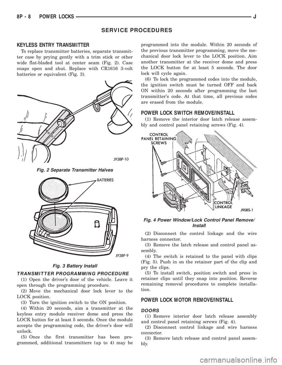
KEYLESS ENTRY TRANSMITTER
To replace transmitter batteries, separate transmit-
ter case by prying gently with a trim stick or other
wide flat-bladed tool at center seam (Fig. 2). Case
snaps open and shut. Replace with CR1616 3-volt
batteries or equivalent (Fig. 3).
TRANSMITTER PROGRAMMING PROCEDURE
(1) Open the driver's door of the vehicle. Leave it
open through the programming procedure.
(2) Move the mechanical door lock lever to the
LOCK position.
(3) Turn the ignition switch to the ON position.
(4) Within 20 seconds, aim a transmitter at the
keyless entry module receiver dome and press the
LOCK button for at least 5 seconds. Once the module
accepts the programming code, the driver's door will
unlock.
(5) Once the first transmitter has been pro-
grammed, additional transmitters (up to 4) may beprogrammed into the module. Within 20 seconds of
the previous transmitter programming, move the me-
chanical door lock lever to the LOCK position. Aim
another transmitter at the receiver dome and press
the LOCK button for at least 5 seconds. The door
lock will cycle again.
(6) To lock the programmed codes into the module,
the ignition switch must be turned OFF and back
ON within 20 seconds after programming the last
transmitter's code. At that time, all previous codes
are erased from the module.
POWER LOCK SWITCH REMOVE/INSTALL
(1) Remove the interior door latch release assem-
bly and control panel retaining screws (Fig. 4).
(2) Disconnect the control linkage and the wire
harness connector.
(3) Remove the latch release and control panel as-
sembly.
(4) The switch is retained to the panel with clips
(Fig. 5). Push in on the retainer part of the clip and
pry the clips.
(5) To install switch, position switch and press in
retainer clips until they snap into position. Reverse
remaining removal procedures to complete installa-
tion.
POWER LOCK MOTOR REMOVE/INSTALL
DOORS
(1) Remove interior door latch release assembly
and control panel retaining screws (Fig. 4).
(2) Disconnect control linkage and wire harness
connector.
(3) Remove latch release and control panel assem-
bly.
Fig. 2 Separate Transmitter Halves
Fig. 3 Battery Install
Fig. 4 Power Window/Lock Control Panel Remove/
Install
8P - 8 POWER LOCKSJ
Page 504 of 2198
POWER WINDOWS
CONTENTS
page page
DIAGNOSIS............................. 1
GENERAL INFORMATION.................. 1SERVICE PROCEDURES................... 7
GENERAL INFORMATION
Power door windows are optional equipment on XJ
(Cherokee) models. The power windows operate only
with the ignition switch in the ON position. This
group covers diagnosis and service of the electrical
components peculiar to the power window system.
For service of mechanical components such as the
regulator, lift plate or window tracks refer to Group
23 - Body Components.
Following are general descriptions of the major
components in the power window system. Refer to
Group 8W - Wiring Diagrams for complete circuit de-
scriptions and diagrams.
POWER WINDOW SWITCH
Both front and rear door windows can be raised or
lowered electrically by operating the four two-way
switches on the driver's door panel. A single two-way
switch on each passenger's door panel operates only
the window on that passenger's door. The switches
cannot be repaired. If faulty, they must be replaced.
POWER WINDOW MOTOR
A permanent magnet reversible motor moves the
window regulator through a cable and drum operat-ing mechanism. A positive and negative battery con-
nection to the two motor terminals will cause the
motor to rotate in one direction. Reversing current
through these same two connections will cause the
motor to rotate in the opposite direction. In addition,
each power window motor is equipped with an inte-
gral automatic re-setting circuit breaker to protect
the motor from overloads. The power window motor
and regulator assembly cannot be repaired. If faulty,
the entire assembly must be replaced.
CIRCUIT BREAKER
An automatic re-setting circuit breaker in the fuse-
block module is used to protect the power window
system circuit. The circuit breaker can protect the
system from a short circuit, and can also protect the
system from an overload condition caused by an ob-
structed or stuck window glass or regulator. The cir-
cuit breaker can not be repaired. If faulty, it must be
replaced.
DIAGNOSIS
It is necessary that the window be free to slide up
and down for the power window system to function
properly. If the window is not free to move up and
down, the motor will overload and trip the circuit
breaker. To determine if the glass is free, disconnect
regulator plate from the glass and slide window up
and down by hand.
An alternate method is to shake the glass in the
door, with the glass positioned between the up and
down stop positions. Check that the glass can be
moved slightly from side to side, front to rear, and up
and down. Then check that window is not boundtight in the tracks. If window is free, proceed with di-
agnosis that follows. If window is not free, refer to
Group 23 - Body Components for service procedures.
CIRCUIT BREAKER
Locate correct circuit breaker in fuseblock module.
Pull out slightly, but be sure that circuit breaker ter-
minals still contact terminals in fuseblock module.
Turn ignition switch to ON position. Connect ground
wire of voltmeter to a good ground. With probe of
voltmeter positive lead, check both terminals of cir-
cuit breaker for battery voltage. If only one terminal
JPOWER WINDOWS 8S - 1
Page 505 of 2198
has battery voltage, circuit breaker is faulty and
must be replaced. If neither terminal has battery
voltage, repair circuit from ignition switch as re-
quired.
POWER WINDOW SWITCH
Before you proceed with this diagnosis, confirm
proper circuit breaker operation. See Circuit Breaker
diagnosis.
(1) Remove switch from door trim panel. See
Power Window Switch Remove/Install. Carefully sep-
arate multiple terminal block on wiring harness from
switch body.
(2) Check for continuity between connector cavity
for switch pin DX and a good ground. See switch con-
tinuity charts for pin identification. There should be
continuity. If OK, go to next step. If not OK, repair
ground circuit as required.
(3) Turn ignition switch to ON position. Check for
battery voltage at connector cavity for switch pin BY.
If OK, go to next step. If not OK, repair wiring to cir-
cuit breaker as required.
(4) Test switch continuity. See switch continuity
charts to determine if continuity is correct in theOFF, LOCK, UP and DOWN switch positions. If OK,
go to Power Window Motor diagnosis. If not OK, re-
place the switch.
POWER WINDOW MOTOR
Before you proceed with this diagnosis, confirm
proper switch operation. See Power Window Switch
diagnosis.
(1) Remove door trim panel (see Power Window
Motor Remove/Install).
(2) Disconnect motor connector. Apply 12 volts
across the motor terminals to check its operation in
one direction. Reverse the polarity to check the oper-
ation in the other direction. Remember, if window is
in the full up or down position the motor will not op-
erate in that direction by design. If OK, repair wire
harness from the motor to the switch as required. If
not OK, replace the motor.
(3) If motor operates in both directions, check op-
eration through its complete up and down travel. If
not OK, refer to Group 23 - Body Components to
check window glass, tracks, and regulator for stick-
ing, binding or improper adjustment.
8S - 2 POWER WINDOWSJ