1995 JEEP CHEROKEE instrument panel
[x] Cancel search: instrument panelPage 1358 of 2198
(1) Make sure the front wheels are in thestraight
aheadposition.
(2) Disconnect the negative (ground) cable from the
battery.
(3) Remove steering wheel from column, refer to
Steering Wheel-Removal.
(4) Column shift vehicles, disconnect the shift ca-
ble grommet by prying it from the shift lever.
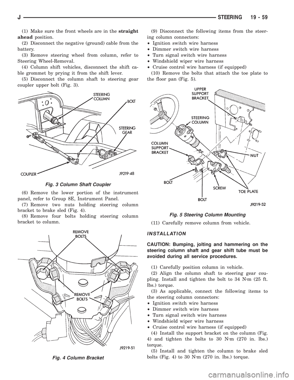
(5) Disconnect the column shaft to steering gear
coupler upper bolt (Fig. 3).
(6) Remove the lower portion of the instrument
panel, refer to Group 8E, Instrument Panel.
(7) Remove two nuts holding steering column
bracket to brake sled (Fig. 4).
(8) Remove four bolts holding steering column
bracket to column.(9) Disconnect the following items from the steer-
ing column connectors:
²Ignition switch wire harness
²Dimmer switch wire harness
²Turn signal switch wire harness
²Windshield wiper wire harness
²Cruise control wire harness (if equipped)
(10) Remove the bolts that attach the toe plate to
the floor pan (Fig. 5).
(11) Carefully remove column from vehicle.
INSTALLATION
CAUTION: Bumping, jolting and hammering on the
steering column shaft and gear shift tube must be
avoided during all service procedures.
(1) Carefully position column in vehicle.
(2) Align the column shaft to steering gear cou-
pling. Install and tighten the bolt to 34 Nzm (25 ft.
lbs.) torque.
(3) As applicable, connect the following items to
the steering column connectors:
²Ignition switch wire harness
²Dimmer switch wire harness
²Turn signal switch wire harness
²Windshield wiper wire harness
²Cruise control wire harness (if equipped)
(4) Install the support bracket on the column (Fig.
4) and tighten the bolts to 30 Nzm (270 in. lbs.)
torque.
(5) Install and tighten the column to brake sled
bolts (Fig. 4) to 30 Nzm (270 in. lbs.) torque.
Fig. 3 Column Shaft Coupler
Fig. 4 Column Bracket
Fig. 5 Steering Column Mounting
JSTEERING 19 - 59
Page 1359 of 2198
(6) Column shift vehicles, install the shift cable
grommet on the shift lever.
(7) Install and tighten the toe plate to floor pan
bolts/nuts to 21.5 Nzm (192 in. lbs.) torque (Fig. 5).
(8) Install the lower portion of the instrument
panel, refer to Group 8E, Instrument Panel.
(9) Install steering wheel on column, refer to Steer-
ing Wheel-Installation.
(10) Connect the negative (ground) cable to the
battery.
NON-TILT STEERING COLUMN
DISASSEMBLYÐCOLUMN OR CONSOLE SHIFT
Steering column removal from the vehicle is not
necessary for;
²Lockplate cover
²Lockplate
²Steering shaft retaining ring
²Canceling cam
²Turn signal switch
²Upper bearing preload spring
²Ignition key/lock cylinder service
The steering column must be removed from
the vehicle to service any other component.
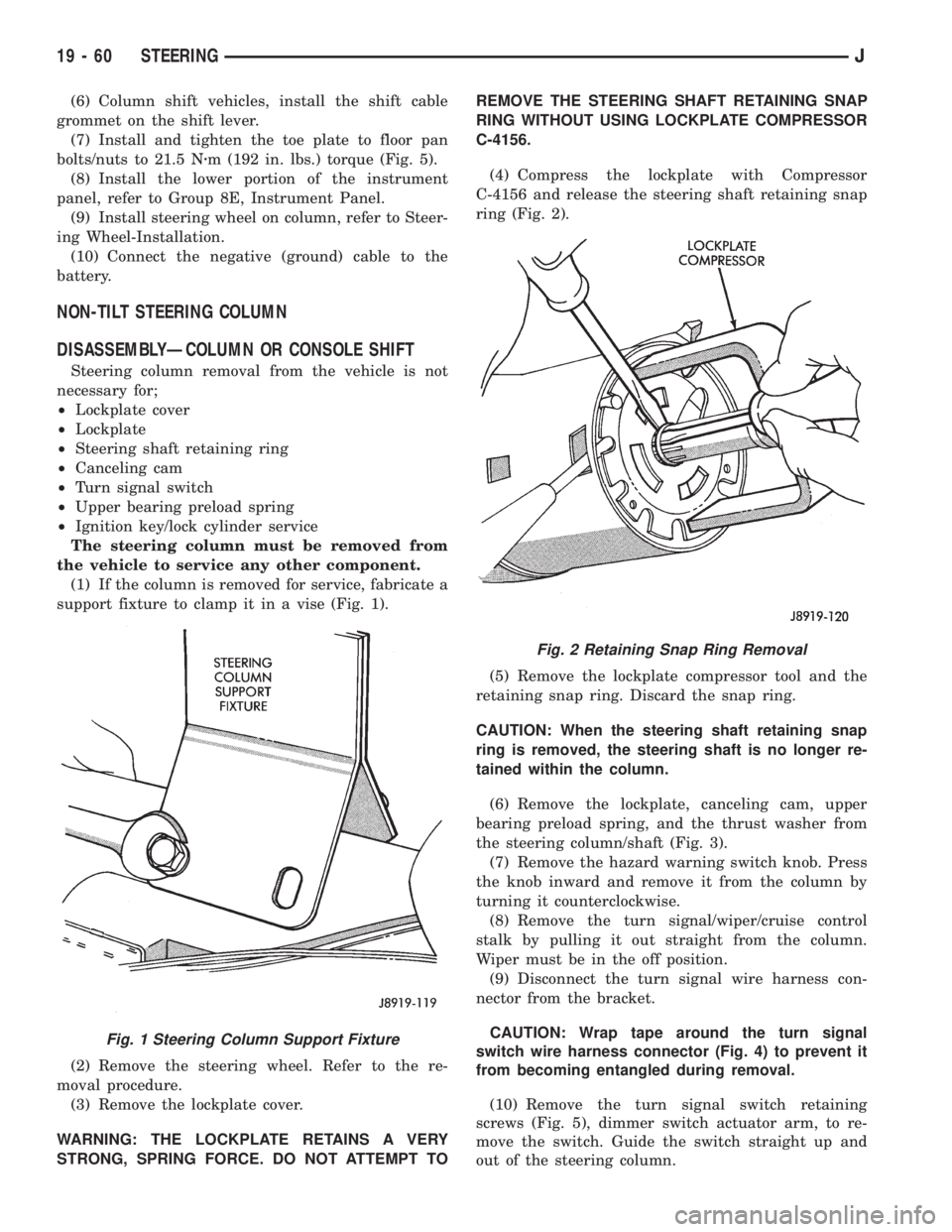
(1) If the column is removed for service, fabricate a
support fixture to clamp it in a vise (Fig. 1).
(2) Remove the steering wheel. Refer to the re-
moval procedure.
(3) Remove the lockplate cover.
WARNING: THE LOCKPLATE RETAINS A VERY
STRONG, SPRING FORCE. DO NOT ATTEMPT TOREMOVE THE STEERING SHAFT RETAINING SNAP
RING WITHOUT USING LOCKPLATE COMPRESSOR
C-4156.
(4) Compress the lockplate with Compressor
C-4156 and release the steering shaft retaining snap
ring (Fig. 2).
(5) Remove the lockplate compressor tool and the
retaining snap ring. Discard the snap ring.
CAUTION: When the steering shaft retaining snap
ring is removed, the steering shaft is no longer re-
tained within the column.
(6) Remove the lockplate, canceling cam, upper
bearing preload spring, and the thrust washer from
the steering column/shaft (Fig. 3).
(7) Remove the hazard warning switch knob. Press
the knob inward and remove it from the column by
turning it counterclockwise.
(8) Remove the turn signal/wiper/cruise control
stalk by pulling it out straight from the column.
Wiper must be in the off position.
(9) Disconnect the turn signal wire harness con-
nector from the bracket.
CAUTION: Wrap tape around the turn signal
switch wire harness connector (Fig. 4) to prevent it
from becoming entangled during removal.
(10) Remove the turn signal switch retaining
screws (Fig. 5), dimmer switch actuator arm, to re-
move the switch. Guide the switch straight up and
out of the steering column.
Fig. 1 Steering Column Support Fixture
Fig. 2 Retaining Snap Ring Removal
19 - 60 STEERINGJ
Page 1560 of 2198
(6) Let engine run at normal curb idle speed, apply
service brakes. Then shift transmission through all
gear ranges and back to PARK (leave engine run-
ning).
(7) Remove dipstick and check fluid level. Add only
enough fluid to bring level to Full mark on dipstick.
Do not overfill.If too much fluid is added, excess
amount can be removed with suction gun and
plastic tubing. Tubing only has to be long
enough to extend into oil pan.
(8) When fluid level is correct, shut engine off, re-
lease park brake, remove funnel, and reseat dipstick
in fill tube.
TRANSMISSION CONTROL MODULE (TCM)
SERVICE
Use the DRB scan tool to diagnose transmission
control module function whenever a fault is sus-
pected. Replace the module only when the scan tool
indicates the module is actually faulty.
TRANSMISSION CONTROL MODULE
REPLACEMENT
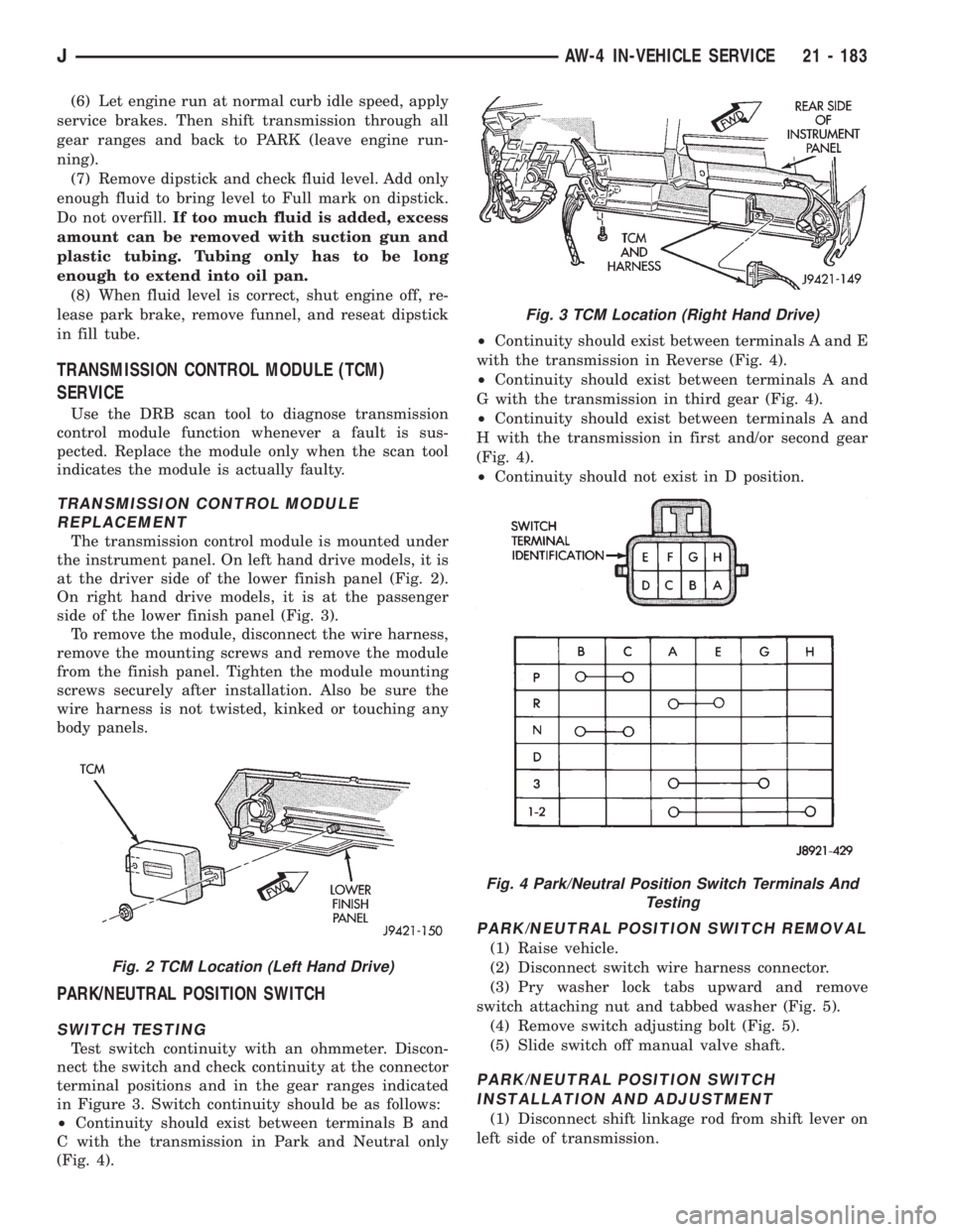
The transmission control module is mounted under
the instrument panel. On left hand drive models, it is
at the driver side of the lower finish panel (Fig. 2).
On right hand drive models, it is at the passenger
side of the lower finish panel (Fig. 3).
To remove the module, disconnect the wire harness,
remove the mounting screws and remove the module
from the finish panel. Tighten the module mounting
screws securely after installation. Also be sure the
wire harness is not twisted, kinked or touching any
body panels.
PARK/NEUTRAL POSITION SWITCH
SWITCH TESTING
Test switch continuity with an ohmmeter. Discon-
nect the switch and check continuity at the connector
terminal positions and in the gear ranges indicated
in Figure 3. Switch continuity should be as follows:
²Continuity should exist between terminals B and
C with the transmission in Park and Neutral only
(Fig. 4).²Continuity should exist between terminals A and E
with the transmission in Reverse (Fig. 4).
²Continuity should exist between terminals A and
G with the transmission in third gear (Fig. 4).
²Continuity should exist between terminals A and
H with the transmission in first and/or second gear
(Fig. 4).
²Continuity should not exist in D position.
PARK/NEUTRAL POSITION SWITCH REMOVAL
(1) Raise vehicle.
(2) Disconnect switch wire harness connector.
(3) Pry washer lock tabs upward and remove
switch attaching nut and tabbed washer (Fig. 5).
(4) Remove switch adjusting bolt (Fig. 5).
(5) Slide switch off manual valve shaft.
PARK/NEUTRAL POSITION SWITCH
INSTALLATION AND ADJUSTMENT
(1) Disconnect shift linkage rod from shift lever on
left side of transmission.
Fig. 2 TCM Location (Left Hand Drive)
Fig. 3 TCM Location (Right Hand Drive)
Fig. 4 Park/Neutral Position Switch Terminals And
Testing
JAW-4 IN-VEHICLE SERVICE 21 - 183
Page 1744 of 2198
(2) Install the hinge nuts on the studs. Tighten the
restraint cable nut to 4 Nzm (38 in-lbs) torque.
Tighten the remaining nuts to 9 Nzm (77 in-lbs)
torque.
If a replacement hinge seal is being installed,
position it around the hinge arm, force it
against the hinge base.
(3) Position the hinge seal around the hinge arm
and on hinge base.
(4) Install the hood.
(5) Adjust the hood as necessary.
HOOD LATCH REPLACEMENTÐXJ
REMOVAL
(1) Remove the screw that attaches the latch to the
hood inner panel (Fig. 15).
(2) Disconnect the latch from the hood and latch
connecting rod. Remove the latch from the hood.
INSTALLATION
(1) Connect the latch to the latch connecting rod
and position it on the hood inner panel.
(2) Install the screw that attaches the latch to the
hood inner panel.
(3) Tighten the screw to 9 Nzm (77 in-lbs) torque.
(4) Test the operation of the latch release cable and
latch.
HOOD LATCH STRIKER REPLACEMENTÐXJ
REMOVE
(1) Remove the grille opening panel (GOP).
(2) Remove the screws that attach the striker to
the radiator baffle (Fig. 19).
(3) Remove the striker and shims from the baffle.
INSTALLATION
(1) Position the shims and striker on the radiator
baffle and install the screws.
(2) Tighten the screws to 21 Nzm (15 ft-lbs) torque.
(3) Test the striker/hood alignment by opening and
closing the hood several times. Adjust the striker, if
necessary.
LATCH RELEASE CABLE REPLACEMENTÐXJ
REMOVAL
(1) Drill out the bellcrank to hood rivet heads and
remove the rivets (Fig. 14).
(2) Disconnect the bellcrank from the latch rod and
the latch release cable. Remove the bellcrank from
the hood.
(3) Disconnect the latch release cable from the
clips on the hood.
(4) Remove the left cowl side trim panel.
(5) Remove the cable bracket screws from the cowl
side panel.(6) Pull the cable through the dash panel and re-
move it from under the instrument panel.
INSTALLATION
(1) Insert the replacement cable end through the
hole in the dash panel into the engine compartment.
(2) Pull the cable forward and seat the grommet in
the dash panel.
(3) Position the cable bracket on the cowl side
panel and install the screws. Tighten the screws to
13 Nzm (111 in-lbs) torque.
(4) Install the left cowl side trim panel.
(5) Connect the cable and latch rod to the
bellcrank.
(6) Position the bellcrank on the hood and install
the rivets.
(7) Attach the cable to the clips.
(8) Test release the cable for proper operation.
SAFETY LATCH STRIKER REPLACEMENTÐXJ
REMOVAL
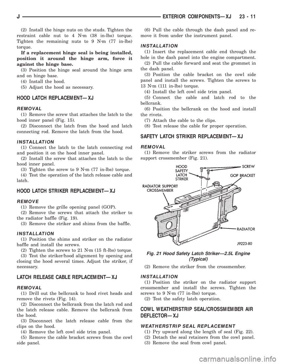
(1) Remove the striker screws from the radiator
support crossmember (Fig. 21).
(2) Remove the striker from the crossmember.
INSTALLATION
(1) Position the striker on the radiator support
crossmember and install the screws. Tighten the
screws to 9 Nzm (77 in-lbs) torque.
(2) Test the safety latch operation.
COWL WEATHERSTRIP SEAL/CROSSMEMBER AIR
DEFLECTORÐXJ
WEATHERSTRIP SEAL REPLACEMENT
(1) Pry upward along the length of seal (Fig. 22).
(2) Detach the seal retainers from the cowl panel.
(3) Remove the seal from cowl panel.
Fig. 21 Hood Safety Latch StrikerÐ2.5L Engine
(Typical)
JEXTERIOR COMPONENTSÐXJ 23 - 11
Page 1813 of 2198
INTERIOR COMPONENTS
INDEX
page page
Assist HandleÐXJ........................ 89
B/C-Pillar and Liftgate Pillar Trim CoversÐXJ.... 88
Bucket Seat Cushion and CoverÐXJ........... 81
Bucket Seat PlatformÐXJ................... 82
Bucket Seatback Cover and FrameÐXJ........ 81
Cargo BarrierÐXJ........................ 101
Cargo LampÐXJ......................... 94
Carpets and Floor MatsÐXJ................. 99
Dome LampÐXJ......................... 93
Front Bucket SeatsÐXJ.................... 81
Front Carpet/MatÐXJ...................... 99
Front Inner Scuff Plate/Cowl Side Trim PanelÐXJ . 86
Front Shoulder Belt/BuckleÐXJ............... 90
Full Floor ConsoleÐXJ..................... 95
HeadlinerÐXJ............................ 92
I/P Ash Receiver Tray LampÐXJ.............. 80
Instrument Cluster BezelÐXJ................ 80
Interior Trim Panels and Scuff PlatesÐXJ....... 84
Jack StorageÐXJ......................... 97
Keyless Entry ReceiverÐXJ................. 93Mini-Console with Floor ShiftÐXJ............. 94
Mini-Floor ConsoleÐXJ..................... 94
Outer Scuff PlatesÐXJ..................... 89
Overhead ConsoleÐXJ..................... 93
Parking Brake Handle CoverÐXJ............. 94
Quarter and Wheelhouse Trim PanelsÐXJ...... 87
Quarter Trim Panel ExtensionÐXJ............. 87
Rear Carpet/MatÐXJ..................... 100
Rear Seat Cushion CoverÐXJ............... 82
Rear Seat CushionÐXJ.................... 82
Rear Seatback CoverÐXJ................... 84
Rear Seatback Latch Striker and BumperÐXJ.... 84
Rear SeatbackÐXJ........................ 83
Rear Shoulder/Lap Belt/BuckleÐXJ............ 91
Sound BarÐXJ........................... 94
Spare Tire/Wheel Holddown and Floor
BracketsÐXJ........................... 98
SunvisorsÐXJ........................... 93
Windshield Side MoldingÐXJ................ 86
INSTRUMENT CLUSTER BEZELÐXJ
REMOVAL
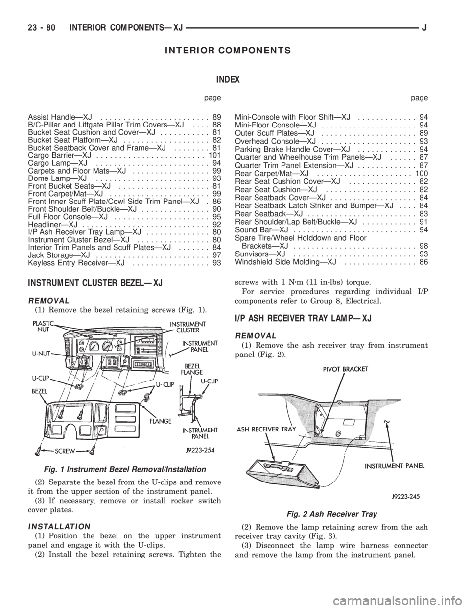
(1) Remove the bezel retaining screws (Fig. 1).
(2) Separate the bezel from the U-clips and remove
it from the upper section of the instrument panel.
(3) If necessary, remove or install rocker switch
cover plates.
INSTALLATION
(1) Position the bezel on the upper instrument
panel and engage it with the U-clips.
(2) Install the bezel retaining screws. Tighten thescrews with 1 Nzm (11 in-lbs) torque.
For service procedures regarding individual I/P
components refer to Group 8, Electrical.
I/P ASH RECEIVER TRAY LAMPÐXJ
REMOVAL
(1) Remove the ash receiver tray from instrument
panel (Fig. 2).
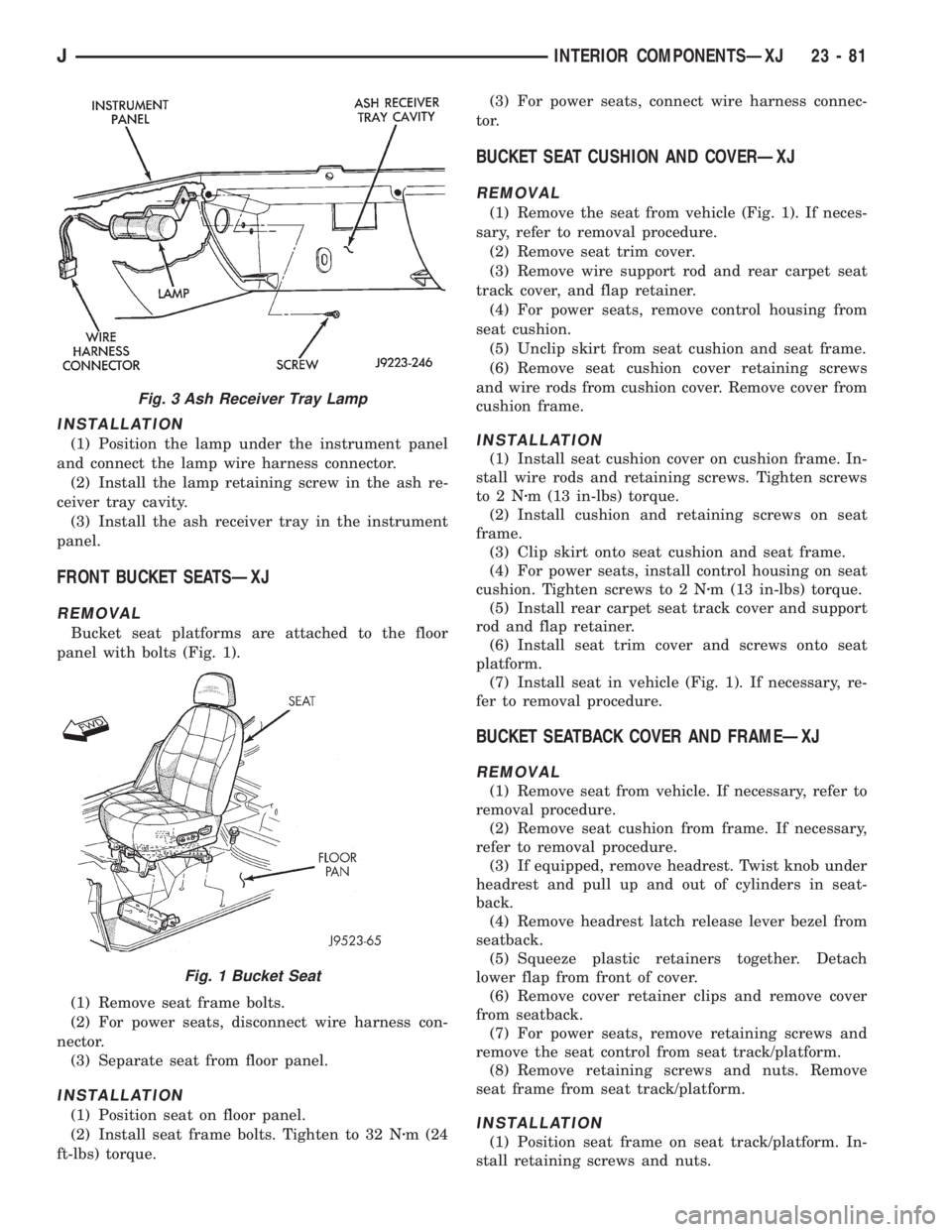
(2) Remove the lamp retaining screw from the ash
receiver tray cavity (Fig. 3).
(3) Disconnect the lamp wire harness connector
and remove the lamp from the instrument panel.
Fig. 1 Instrument Bezel Removal/Installation
Fig. 2 Ash Receiver Tray
23 - 80 INTERIOR COMPONENTSÐXJJ
Page 1814 of 2198
INSTALLATION
(1) Position the lamp under the instrument panel
and connect the lamp wire harness connector.
(2) Install the lamp retaining screw in the ash re-
ceiver tray cavity.
(3) Install the ash receiver tray in the instrument
panel.
FRONT BUCKET SEATSÐXJ
REMOVAL
Bucket seat platforms are attached to the floor
panel with bolts (Fig. 1).
(1) Remove seat frame bolts.
(2) For power seats, disconnect wire harness con-
nector.
(3) Separate seat from floor panel.
INSTALLATION
(1) Position seat on floor panel.
(2) Install seat frame bolts. Tighten to 32 Nzm (24
ft-lbs) torque.(3) For power seats, connect wire harness connec-
tor.
BUCKET SEAT CUSHION AND COVERÐXJ
REMOVAL
(1) Remove the seat from vehicle (Fig. 1). If neces-
sary, refer to removal procedure.
(2) Remove seat trim cover.
(3) Remove wire support rod and rear carpet seat
track cover, and flap retainer.
(4) For power seats, remove control housing from
seat cushion.
(5) Unclip skirt from seat cushion and seat frame.
(6) Remove seat cushion cover retaining screws
and wire rods from cushion cover. Remove cover from
cushion frame.
INSTALLATION
(1) Install seat cushion cover on cushion frame. In-
stall wire rods and retaining screws. Tighten screws
to2Nzm (13 in-lbs) torque.
(2) Install cushion and retaining screws on seat
frame.
(3) Clip skirt onto seat cushion and seat frame.
(4) For power seats, install control housing on seat
cushion. Tighten screws to 2 Nzm (13 in-lbs) torque.
(5) Install rear carpet seat track cover and support
rod and flap retainer.
(6) Install seat trim cover and screws onto seat
platform.
(7) Install seat in vehicle (Fig. 1). If necessary, re-
fer to removal procedure.
BUCKET SEATBACK COVER AND FRAMEÐXJ
REMOVAL
(1) Remove seat from vehicle. If necessary, refer to
removal procedure.
(2) Remove seat cushion from frame. If necessary,
refer to removal procedure.
(3) If equipped, remove headrest. Twist knob under
headrest and pull up and out of cylinders in seat-
back.
(4) Remove headrest latch release lever bezel from
seatback.
(5) Squeeze plastic retainers together. Detach
lower flap from front of cover.
(6) Remove cover retainer clips and remove cover
from seatback.
(7) For power seats, remove retaining screws and
remove the seat control from seat track/platform.
(8) Remove retaining screws and nuts. Remove
seat frame from seat track/platform.
INSTALLATION
(1) Position seat frame on seat track/platform. In-
stall retaining screws and nuts.
Fig. 3 Ash Receiver Tray Lamp
Fig. 1 Bucket Seat
JINTERIOR COMPONENTSÐXJ 23 - 81
Page 1884 of 2198
INTERIOR COMPONENTS
INDEX
page page
Add-A-TrunkÐYJ........................ 157
Bucket SeatsÐYJ........................ 153
CarpetÐYJ............................. 156
Floor ConsolesÐYJ...................... 155
Front Shoulder BeltsÐYJ.................. 154
Glove BoxÐYJ.......................... 152
Instrument Cluster and Gauge HousingsÐYJ.... 151Instrument Cluster BezelÐYJ............... 151
Instrument Panel ComponentsÐYJ........... 152
Instrument PanelÐYJ..................... 151
Rear Bench SeatÐYJ..................... 153
Rear Shoulder BeltsÐYJ................... 154
SeatsÐYJ............................. 153
SunvisorsÐYJ.......................... 155
INSTRUMENT PANELÐYJ
The instrument panel is constructed of sheet metal
and is attached to cowl panel with screws. The in-
strument panel and defroster grille pad is attached
to the instrument panel with screws.
INSTRUMENT CLUSTER AND GAUGE HOUSINGSÐ
YJ
REMOVAL
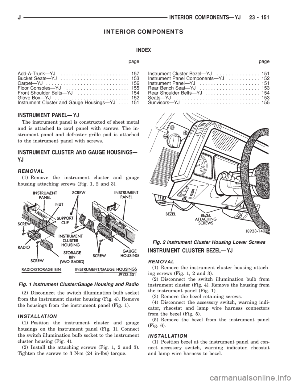
(1) Remove the instrument cluster and gauge
housing attaching screws (Fig. 1, 2 and 3).
(2) Disconnect the switch illumination bulb socket
from the instrument cluster housing (Fig. 4). Remove
the housings from the instrument panel (Fig. 1).
INSTALLATION
(1) Position the instrument cluster and gauge
housings on the instrument panel (Fig. 1). Connect
the switch illumination bulb socket to the instrument
cluster housing (Fig. 4).
(2) Install the attaching screws (Fig. 1, 2 and 3).
Tighten the screws to 3 Nzm (24 in-lbs) torque.
INSTRUMENT CLUSTER BEZELÐYJ
REMOVAL
(1) Remove the instrument cluster housing attach-
ing screws (Fig. 1, 2 and 3).
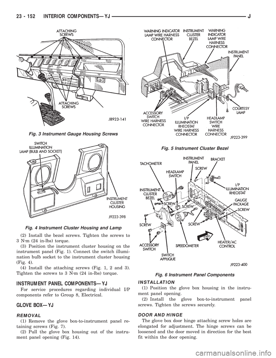
(2) Disconnect the switch illumination bulb from
instrument cluster (Fig. 4). Remove the housing from
the instrument panel (Fig. 1).
(3) Remove the bezel retaining screws.
(4) Disconnect the accessory switch, warning indi-
cator, rheostat and lamp wire harness connectors
from the bezel (Fig. 5).
(5) Remove the bezel from the instrument panel
(Fig. 6).
INSTALLATION
(1) Position bezel at the instrument panel and con-
nect accessory switch, warning indicator, rheostat
and lamp wire harness to bezel.
Fig. 1 Instrument Cluster/Gauge Housing and Radio
Fig. 2 Instrument Cluster Housing Lower Screws
JINTERIOR COMPONENTSÐYJ 23 - 151
Page 1885 of 2198
(2) Install the bezel screws. Tighten the screws to
3Nzm (24 in-lbs) torque.
(3) Position the instrument cluster housing on the
instrument panel (Fig. 1). Connect the switch illumi-
nation bulb socket to the instrument cluster housing
(Fig. 4).
(4) Install the attaching screws (Fig. 1, 2 and 3).
Tighten the screws to 3 Nzm (24 in-lbs) torque.
INSTRUMENT PANEL COMPONENTSÐYJ
For service procedures regarding individual I/P
components refer to Group 8, Electrical.
GLOVE BOXÐYJ
REMOVAL
(1) Remove the glove box-to-instrument panel re-
taining screws (Fig. 7).
(2) Pull the glove box housing out of the instru-
ment panel opening (Fig. 14).
INSTALLATION
(1) Position the glove box housing in the instru-
ment panel opening.
(2) Install the glove box-to-instrument panel
screws. Tighten the screws securely.
DOOR AND HINGE
The glove box door hinge attaching screw holes are
elongated for adjustment. The hinge screws can be
loosened and the door moved in direction for the best
fit within the door opening.
Fig. 3 Instrument Gauge Housing Screws
Fig. 4 Instrument Cluster Housing and Lamp
Fig. 5 Instrument Cluster Bezel
Fig. 6 Instrument Panel Components
23 - 152 INTERIOR COMPONENTSÐYJJ