1994 MAZDA MX-5 engine warning light
[x] Cancel search: engine warning lightPage 23 of 1708
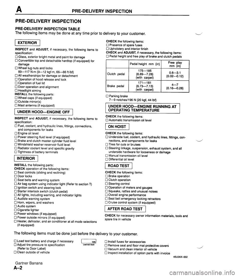
PRE-DELIVERY INSPECTION PRE-DELIVERY INSPECTION PRE-DELIVERY INSPECTION TABLE The following items may be done at any time prior to delivery to your customer. INSPECT and ADJUST, if necessary, the following items to specification: 0 Glass, exterior bright metal and paint for damage 0 Convertible top and detachable hardtop (if equipped) for damage 0 Wheel lug nuts and locks 89-117 N.m (9-1 2 kgf.m, 66-86 ft4bf) 0 All weatherstrips for damage or detachment Operation of hood release and lock Operation of fuel lid 0 Door operation and alignment Headlight aiming INSTALL the following parts: Wheel caps (if equipped) 0 Outside mirror(s) 0 Mast antenna (if equipped) UNDER HOOD-ENGINE OFF INSPECT and ADJUST, if necessary, the following items to specification : Fuel, coolant, and hydraulic lines, fittings, connections, and components for leaks Engine oil level 0 Power steering fluid level (if equipped) Brake and clutch master cylinder fluid level 0 Windshield washer reservoir fluid level 0 Radiator coolant level and specific gravity 0 Tightness of battery terminals pKiq INSTALL the following parts: CHECK operation of the following items: 0 Seat controls (sliding and reclining) 0 Door locks 0 Seat belts and warning system 0 Air bag system using indicator light (Refer to section T) Ignition switch and steering lock 0 Starter interlock switch (clutch pedal) All lights, including warning, and indicator lights 0 Audible warning system 0 Horn, wipers, and washers Audio system 0 Cigarette lighter Power windows (if equipped) 0 Power outside mirrors (if equipped) 0 Heater, defroster, and air conditioner at all mode selections (if equipped) CHECK the following items: Presence of spare fuses 0 Upholstery and interior finish CHECK and ADJUST, if necessary, the following items: 0 Pedal height and free play of brake and clutch pedals I Pedal height mm {in} I Ft: $iy I Clutch pedal {6.89--7.28) (with carpet) Parking brake 7-9 notchesil96 N (20 kgf, 44 Ibf) 0.63.1 (0.024. 12) Brake pedal RUNNING AT OPERATING TEMPERATURE CHECK the following items: 0 Automatic transmission oil level 171-181 (6.73--7.13) (with carpet) I ON HOIST I 4--7 {0.16-0.28} CHECK the following items: 0 Underside fuel, coolant, and hydraulic lines, fittings, con- nections, and components for leaks 4 Tires for cuts or bruises 0 Steering linkage, suspension, exhaust system, and all underside hardware for looseness or damage Manual transmission oil level Differential oil level I ROAD TEST I CHECK the following items: Brake operation Clutch operation 0 Steering control 0 Operation of meters and gauges Squeaks, rattles and unusual noises 0 Overall engine performance Seat belt emergency locking retractors 0 Cruise control system (if equipped) I AFTER ROAD TEST I CHECK for necessary owner information materials, tools and spare tire in vehicle The following items must be done just before the delivery to your customer. 0 Load test battery and charge if necessary -1 Install fuses for accessories Adjust tire pressure to specification Load test fesuk 0 Remove seat and floor mat protective covers (Refer to Door Label) 0 Vacuum and clean interior of vehicle Clean outside of vehicle Inspect installation of option parts with invoice 45UOAX-002 Gartner Banana
Page 165 of 1708

TROUBLESHOOTING GUIDE Warning Fuel vapor is hazardous. It can very easily ignite, causing serious injury and damage. Always keep sparks and flames away from fuel. Fuel in the fuel system is under high pressure when the engine is not running. 4 Warning Fuel line spills and leaks are dangerous. Fuel can ignite and cause serious injuries or death and damage. Fuel can also irritate skin and eyes. To prevent this, always complete the following "Fuel Line Safety Procedures". 35UOFX-008 F-73 F-73 F-74 Fuel Line Safety Procedures A. Release the fuel pressure before disconnecting a fuel line. 1. Start the engine. u 2. Disconnect the fuel pump relay connector. 3. After the engine stalls, turn the ignition switch to OFF. 4. Reconnect the fuel pump relay connector. B. Avoid leakage. 1. When disconnecting a fuel line hose, wrap a rag around it to protect against fuel leakage. 2. Plug the hose after removal. C. Install hose clamps to secure the fuel pressure gauge connections. Self-Diagnosis Checker does not indicate Diagnostic Trouble Code No. but MIL comes on Self-Diagnosis Checker indicates Diagnostic Trouble Code No, of input device but MIL never comes ON Blower fan operates but no cool air is discharged 32 33 34 Pinching Hose When pinching an air hose or fuel hose with pliers, wrap the hose with a rag to prevent damage. MIL always ON MIL never ON NC does not work Checking ignition spark When checking ignition spark condition, hold the high- tension lead with insulated pliers. Note If a timing light is used to check for spark, some lights do not light at the number 2 and 4 cylinders even if the ignition system is normal. J Gartner Banana
Page 314 of 1708

CHARGING SYSTEM G TROUBLESHOOTING Check 1 Check if battery p Check battery (Refer to page G-8) J Check 2 I. Turn ignition switch ON Check wire harness 2. Check if voltage exists at each terminal of alternator Check 3 YES 1. Start engine Check alternator (Refer to page G-10) 2. Check if alternator warning light goes off I YES Check if drive belt t Adjust or replace drive belt (Refer to page G-14) 1 YES I Check for dark current (Refer to page G-3) I Check 1 BATTERY r"; Check 3 I ALTERNATOR WARNING LIGHT Check 2 B+: Battery positive voltage I I I B 1 Approx. 12V 1 Approx. 12V I B+ ON ON (Idle) L S 45UOGX-006 OV Approx. 12V Approx. 1V Approx. 12V B+ B+ Gartner Banana
Page 324 of 1708
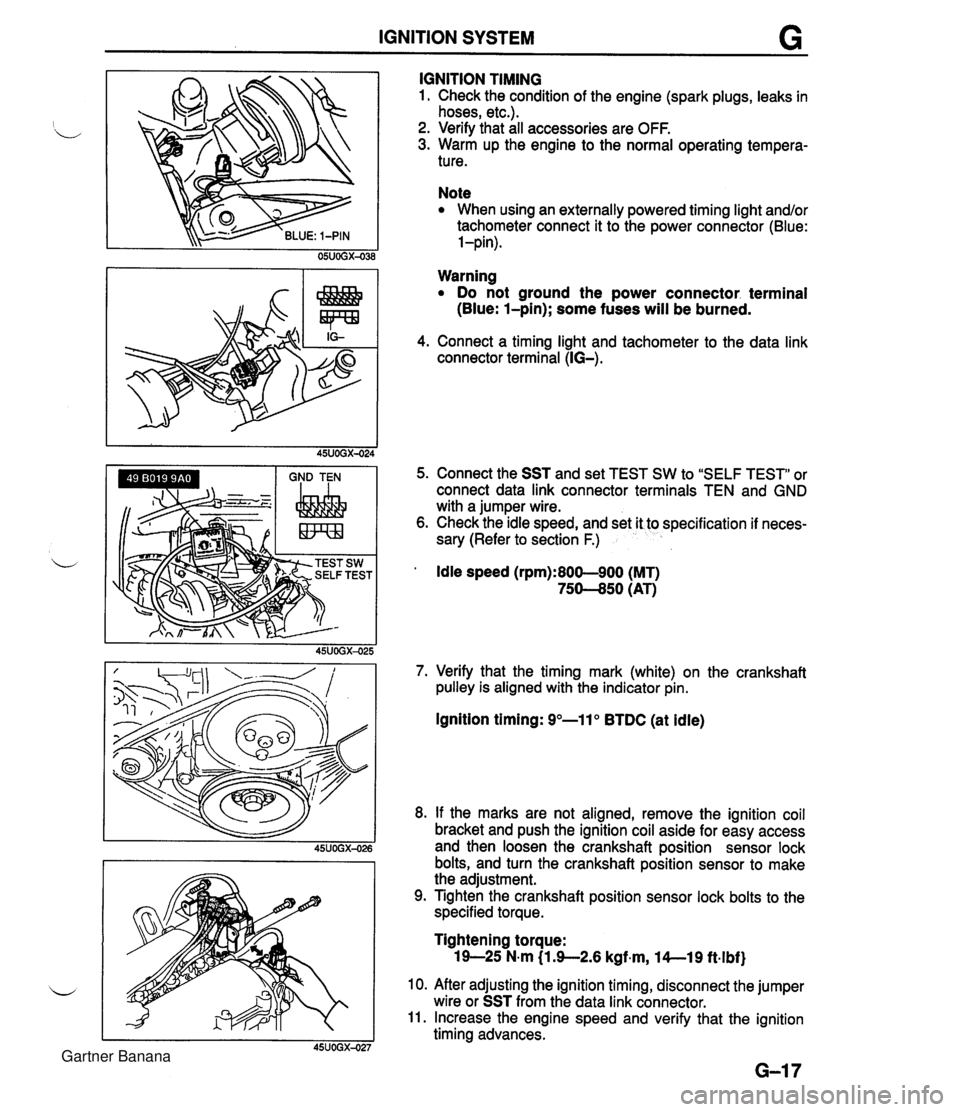
IGNITION SYSTEM G GND TEN I I I IGNITION TIMING 1. Check the condition of the engine (spark plugs, leaks in hoses, etc.). 2. Verify that all accessories are OFF. 3. Warm up the engine to the normal operating tempera- ture. Note When using an externally powered timing light and/or tachometer connect it to the power connector (Blue: l-pin). Warning Do not ground the power connector. terminal (Blue: l-pin); some fuses will be burned. 4. Connect a timing light and tachometer to the data link connector terminal (IG-). 5. Connect the SST and set TEST SW to "SELF TEST" or connect data link connector terminals TEN and GND with a jumper wire. 6. Check the idle speed, and set it to specification if neces- sary (Refer to section F.) ' Idle speed (rpm):800-900 (MT) 75-50 (AT) 7. Verify that the timing mark (white) on the crankshaft pulley is aligned with the indicator pin. Ignition timing: 9"-11" BTDC (at idle) 8. If the marks are not aligned, remove the ignition coil bracket and push the ignition coil aside for easy access and then loosen the crankshaft position sensor lock bolts, and turn the crankshaft position sensor to make the adjustment. 9. Tighten the crankshaft position sensor lock bolts to the specified torque. Tightening torque: 19-25 N-m (1 3-2.6 kgf~m, l4--19 ft.lbf) 10. After adjusting the ignition timing, disconnect the jumper wire or SST from the data link connector. 11. Increase the engine speed and verify that the ignition timing advances. Gartner Banana
Page 867 of 1708

T INSTRUMENT CLUSTER INSTRUMENT CLUSTER STRUCTURAL VIEW 1. Speedometer 2. Tachometer 3. Water temperature gauge 4. Fuel gauge 5. Oil pressure gauge 6. Warning and indicator lights 7. Trip meter 8. Odometer DESCRIPTION Speedometer Two scales are shown on the speedometer face. The main scale for U.S. specification vehicles is MPH (0-140 MPH); the main scale for Canada specification vehicles is kmlh (0-220 kmlh). The odometer indication is the same as the main scale. Tachometer The tachometer has a RED STRIPED ZONE (6,500-7,000 rpm) that indicates momentary allowable engine speed. The engine should not be operated in the RED ZONE (7,000-8,000 rpm). Fuel Gauge 2 The fuel gauge continues to indicate the amount of fuel remaining in the fuel tank after the ignition switch has been turned OFF. Gartner Banana
Page 884 of 1708

WARNING LIGHT AND SENDER UNIT T OHMMETER Washer Level Indicator lnspection 1. Disconnect the connector from the washer level sensor. 2. Jump terminal-wire L (harness side) to a body ground. 3. Start the engine and check that the WASHER indicator illuminates. 4. If there is no illumination, check the bulb, wiring harness, and sensor. Replace or repair as necessary. Washer Level Sensor lnspection 1. Connect the sensor connector (sensor side) to an ohm- meter. 2. Move the sensor float up and down. 3. Verify that there is continuity when the float is at the low- est point. BRAKE FLUID LEVEL SENSOR lnspection 1. Check for continuity of the sensor. 2. If continuity is not as specified, replace the level sensor. Float level Below MIN Above MIN BUCKLE SWITCt Continuity Yes No OHMMETER -1 PARKING BRAKE SWITCH lnspection 1. Disconnect the parking brake switch connector. 2. Check for continuity between the switch connector and ground. I Lever I Continuity I 3. If continuity is not as specified, adjust or replace the parking brake switch. (Refer to section P.) Pulled one notch Released BUCKLE SWITCH lnspection 1. Disconnect the buckle switch connector 2. Check for continuity of the switch. Yes No Seat belt I Continuity Seat belt buckled Seat belt unbuckled No Yes 3. If continuity is not as specified, replace the buckle switch. Gartner Banana
Page 918 of 1708

LIGHTING SYSTEM T Symptom: Daytime running lights (DRL) do not illuminate. (Turn signals function normally.) DRL operate with engine running and following switches are off: Headlight switch Turn signal switch (Selected turn signal light flashes, other light remains illumi- nated) Hazard warning switch Parking brake switch (Parking brake released) Step 1 1. Position the vehicle on a flat surface and block the wheels to prevent vehicle movement. 2. Turn the ignition switch to ON. 3. Measure the voltage at the following terminal wires of the DRL control unit. 4. If correct, replace the DRL control unit. B+: Battery positive voltage Step 2 1. Disconnect the parking brake switch connector. 2. Check for continuity between the terminal of the switch and a body ground. Terminal J (L) u Connected to WIPER 20A fuse I(B) B (R) C (WIR) Parking brake lever Pulled one notch Continuity Yes Released Test condition Constant GND Parking brake switch Headlight switch No I 3. If not as specified, adjust or replace the parking brake switch. 4. If correct, repair wiring harness. (DRL control unit - Parking brake switch) Specification B+ Constant Parking brake released Headlight switch off Action Repair wiring harness (WIPER 20A - DRL control unit) Other B+ Other Repair wiring harness (DRL control unit - GND) Go to Step 2 Go to Step 3 Gartner Banana