1994 MAZDA MX-5 fuel pressure
[x] Cancel search: fuel pressurePage 867 of 1708

T INSTRUMENT CLUSTER INSTRUMENT CLUSTER STRUCTURAL VIEW 1. Speedometer 2. Tachometer 3. Water temperature gauge 4. Fuel gauge 5. Oil pressure gauge 6. Warning and indicator lights 7. Trip meter 8. Odometer DESCRIPTION Speedometer Two scales are shown on the speedometer face. The main scale for U.S. specification vehicles is MPH (0-140 MPH); the main scale for Canada specification vehicles is kmlh (0-220 kmlh). The odometer indication is the same as the main scale. Tachometer The tachometer has a RED STRIPED ZONE (6,500-7,000 rpm) that indicates momentary allowable engine speed. The engine should not be operated in the RED ZONE (7,000-8,000 rpm). Fuel Gauge 2 The fuel gauge continues to indicate the amount of fuel remaining in the fuel tank after the ignition switch has been turned OFF. Gartner Banana
Page 873 of 1708

T INSTRUMENT CLUSTER Symptom: Oil pressure gauge does not operate. 05UOTX-468 Preparation SST I 49 0839 285 For inspection of Checker, fuel gauges and thermometer Step 1 1. Disconnect the connector from the oil pressure sensor. 2. Connect the red lead of the SST to the A (YIR) terminal wire and the black lead to ground. 3. Turn the ignition switch ON. 4. Set the SST to the resistance values shown in the figure. To get an accurate reading, wait 2 minutes after setting each value. 5. Verify that the gauge indicates the correct values. The al- lowable indication error is twice the width of the needle. I Incorrect I GO to step 2 Gauge display Correct Step 2 1. Remove the instrument cluster. (Refer to page T-29.) 2. Apply battery positive voltage to terminal 2K and ground to terminal 2J. 3. Connect the red lead of the SST to terminal 26 and the black lead to ground. Action Replace oil pressure sensor 4. Set the SST to the resistance values shown in the figure. To get an accurate reading, wait 2 minutes after setting each value. 5. Verify that the gauge indicates the correct values. The al- lowable indication error is twice the width of the needle. Incorrect I Replace oil pressure gauge Gauge display Correct Action Repair wiring harness (Instrument cluster - Oil pressure sensor) Gartner Banana
Page 876 of 1708

INSTRUMENT CLUSTER T FUEL GAUGE Preparation SST f OIL PRESSURE GAUGE Preparation SST L lnspection 1. Remove the instrument cluster. (Refer to page T-29.) 2. Apply battery positive voltage to terminal 2K and ground to terminal 2J. 3. Connect the red lead of the SST to terminal 1A and the black lead to ground. 4. Set the SST to the resistance values shown in the figure. To get an accurate reading, wait 2 minutes after setting each value. 5. Verify that the gauge indicates the correct values. The al- lowable indication error is twice the width of the needle. 6. If not as specified, replace the fuel gauge. 49 0839 285 Checker, fuel and thermometer For inspection of gauges Inspection 1. Remove the instrument cluster. (Refer to page T-29.) 2. Apply battery positive voltage to terminal 2K and ground to terminal 2J. 3. Connect the red lead of the SST to terminal 2B and the black lead to ground. 49 0839 285 Checker, fuel and thermometer For inspection of gauges Gartner Banana
Page 877 of 1708

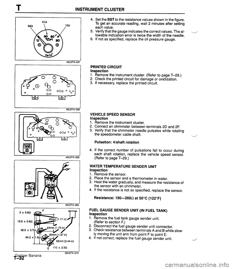
T INSTRUMENT CLUSTER 4. Set the SST to the resistance values shown in the figure. To get an accurate reading, wait 2 minutes after setting each value. 5. Verify that the gauge indicates the correct values. The al- \J lowable indication error is twice the width of the needle. 6. If not as specified, replace the oil pressure gauge. PRINTED CIRCUIT lnspection 1. Remove the instrument cluster. (Refer to page T-29.) 2. Check the printed circuit for damage or oxidization. 3. If necessary, replace the printed circuit. VEHICLE SPEED SENSOR lnspection 1. Remove the instrument cluster. 2. Connect an ohmmeter between terminals 2D and 2F. 3. Verify that the ohmmeter needle pulsates while rotating the speedometer cable shaft. ~ Pulsation: Ushaft rotation 4. If the correct number of pulsations fail to occur during each shaft rotation, replace the vehicle speed sensor. (Refer to page T-29.) WATER TEMPERATURE SENDER UNlT lnspection 1. Remove the sensor. 2. Place the sensor and a thermometer in water. 3. Heat the water gradually, and measure the resistance of the sensor with an ohmmeter. 4. If the resistance is not as specified, replace the sensor. Resistance: 190-260Q at 50°C (1 22°F) FUEL GAUGE SENDER UNlT (IN FUEL TANK) lnspection 1. Remove the fuel tank gauge sender unit. (Refer to section F.) 2. Disconnect the fuel gauge sender unit connector. 3. Check resistance between terminals A and B while slow- ly moving the unit arm from point F to point E. 4. If not correct, replace the fuel gauge sender unit. 2 Gartner Banana
Page 1114 of 1708
![MAZDA MX-5 1994 Workshop Manual TD TECHNICAL DATA Idle speed rpm 1 800-900 (850 2 50) [MT], 750-850 (800 f 50) [ATJ lanition timina BTDC I 9"-11 (10 f 1") u F. FUEL AND EMISSION CONTROL SYSTEMS - Engine ltem Item 1 Throat diam MAZDA MX-5 1994 Workshop Manual TD TECHNICAL DATA Idle speed rpm 1 800-900 (850 2 50) [MT], 750-850 (800 f 50) [ATJ lanition timina BTDC I 9"-11 (10 f 1") u F. FUEL AND EMISSION CONTROL SYSTEMS - Engine ltem Item 1 Throat diam](/manual-img/28/57072/w960_57072-1113.png)
TD TECHNICAL DATA Idle speed rpm 1 800-900 (850 2 50) [MT]', 750-850 (800 f 50) [ATJ' lanition timina BTDC I 9"-11' (10' f 1")' u' F. FUEL AND EMISSION CONTROL SYSTEMS - Engine ltem Item 1 Throat diameter mm {in) 1 55 (2.2) 1 Antifreeze solution BP DOHC Specification 1 Throttle body Fuel pump TY pe I Impeller (in-tank) Coolant protection Above -1 6°C (3°F) Above -26°C (-15°F) Above -40°C {-40°n Tv~e -. Output pressure kPa (kgf/cm2, psi) I 294-437 {3.0--6.5,43--92) Fuel filter Specific gravity at 20°C {WF) 1.054 1.066 1.078 Volume percentage % Horizontal draft Water 65 55 45 -. . - Regulating pressure kPa {kgf/cm2, psi) I 280-289 I2.85--2.95, 40.141.9) Fuel iniector Coolant 35 45 55 TY pe IAC valve Solenoid resistance n 1 10.7-1 2.3 (at 20°C (68°F)) Low-pressure side TYP~ Type of drive Resistance n Purge solenoid valve Solenoid resistance n 1 23-27 (at 20°C (68°F)) I Nylon element Pressure regulator TY pe High-ohmic Voltage 13.8 (at 20°C (68"FI) Engine coolant temperature sensor 7 20°C {68"F) I 2.21 -2.69 Resistance kn I 80°C (1 76OF} I 0.287-0.349 High-pressure side Diaphragm i/ Crankshaft position sensor Air valve Openin~l temperature OC {OF) I Below 45 (1 131 Paper element Twe 1 Fuel tank I Hall effect . . . . . . . Capacity L {US gal, Imp gal) I 48 {12.7, 10.5) Air cleaner housing Element type Free play mm (in) I 1-3 {0.039--0.118) I Fuel Oil permeated Specification Accelerator cable Unleaded regular (RON 87 or higher) J +....with system selector (49 B019 9AO) test switch at SELF TEST Gartner Banana
Page 1122 of 1708

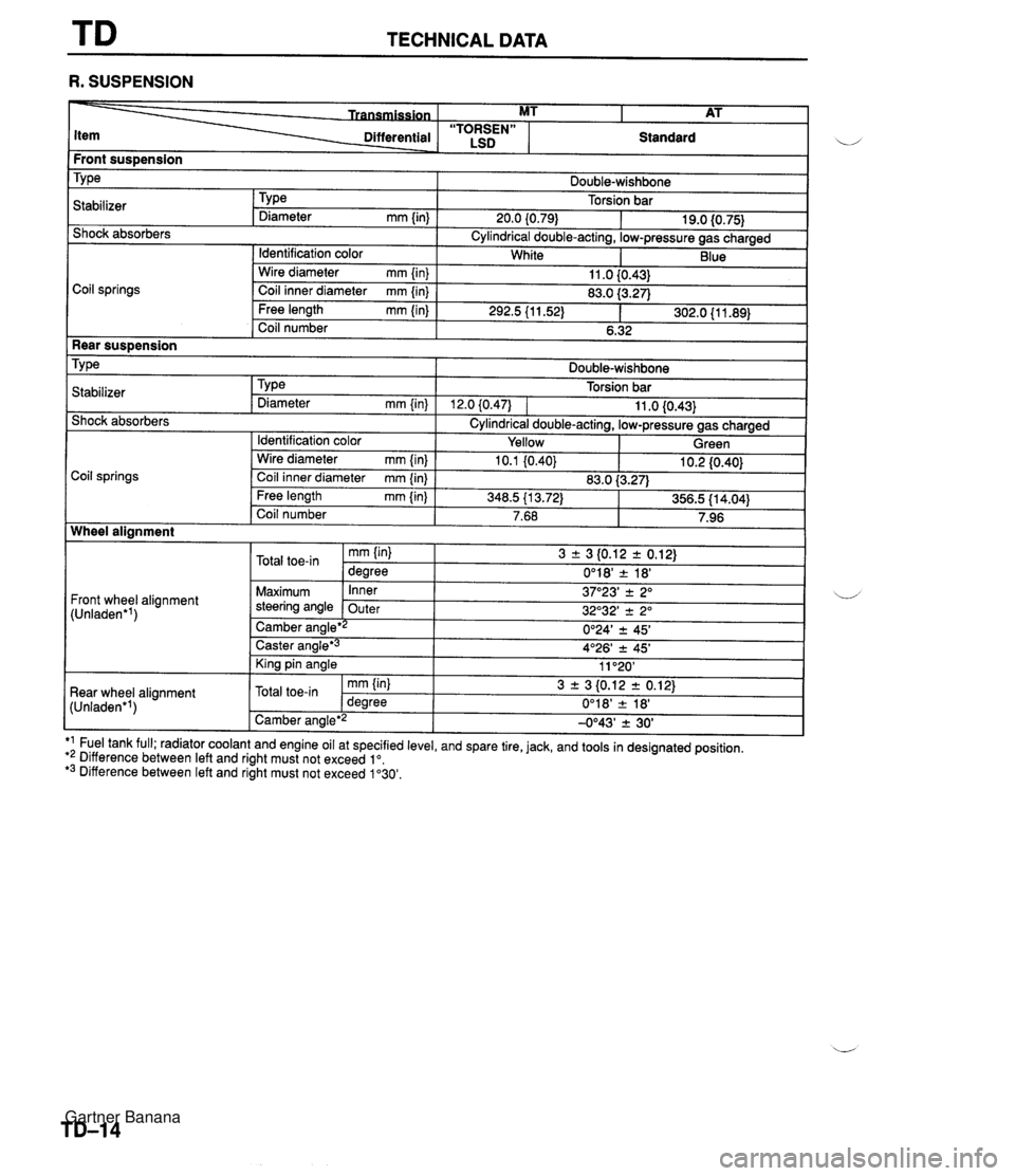
TECHNICAL DATA R. SUSPENSION Front sus~ension I i/ Differential - . - ~- Coil springs MT I AT Shock absorbers "TORSEN" LSD TY ~a Cylindrical double-acting, low-pressure gas charged Standard Stabilizer Double-wishbone Torsion bar Wire diameter mm {in) Coil inner diameter mm {in} Rear suspension Tv~e I Double-wishbone TY pe Diameter mm {in) 20.0 (0.79) I Identification color 11 .O {0.43} 83.0 f3.27) . . Free length mm {in) Coil number 19.0 {0.75} . . 292.5 (1 1.52) 1 302.0 {I 1.89) 6.32 I - . I1 . ,I . , I Shock absorbers Cylindrical double-acting, low-pressure gas charged White I I Identification color I Yellow I Green I Blue Torsion bar 12.0 (0.471 1 11 .O 10.43) .a Stabilizer TYPe Diameter mm {in) Coil springs Wheel alignment I Front wheel alignment (Unladen'') I I - Caster angle*3 King pin angle I tun'aoen 'I 1 Camber angle'2 -0°43' 2 30' I I - Wire diameter mm {in) Coil inner diameter mm {in) Free length mm {in} Coil number Maximum steering angle 4O26' -c 45' 11 "20' Rear wheel alignment ,, l-l_A_-*i, *1 Fuel tank full; radiator coolant and engine oil at specified level, and spare tire, jack, and tools in designated position. *2 Difference between left and right must not exceed lo. *3 Difference between left and right must not exceed 1'30'. 10.1 (0.40) Inner Outer 10.2 I0.40) mm (in) Camber ana~e*~ J 3 + 3 10.12 r 0.12) 0°18' 2 18' -. - 3 r 3 {0.12 2 0.12) 0'24' 2 45' 37O23' 2 2" 32O32' 2 2" Total toe-in 83.0 i3.27) U' mm {in} degree 348.5 113.72) Total toe-in 356.5 {I 4.04) dearee 7.68 0'18' & 18' 7.96 Gartner Banana
Page 1380 of 1708

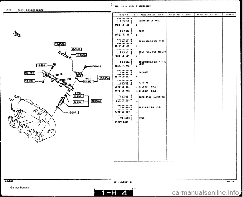
I 1525 1 * FUEL DISTRtBUTOR 1325 FUEL DISTRIBUTOR J It [HSULATOR ,FUEL DIST. BOLT, FUEL DIST RIBUT 0 3 RING, '0' (ILLUST. Ho.11 (ILLUST. N0.23 INSULATOR XNJECTSON PRESSURE RO. ,FUEL HOSE Gartner Banana
Page 1699 of 1708

ALPHABETICAL INDEX *%* ENGLISH *** GASKET'A' ,DUST COVER----- 1-114 GAUGEIFUEL TANK---------- 1-J14 GAUGE,OIL LEVEL---------- 1-DB 1 -H3 GEAR------..-------------- GEAR SET,DRlVEN-SPEED---- 1-M7 GEAR SET,FINAL----------- 1-H11 T -1 11 A-LAA GEAR,ADJUST-------------- l-Fll GEAR, COUNTER-- ----------- 1-H6 GEAR,COUNTER REVERSE----- 1-66 GEAR,COUNl'ER SHAFT------- 1-G6 GEAR,DIFF.SIDE----------- GEAR,DRIVEN-------------- 1-111 1-06 GEAR,INNER----.----------- 1-N4 GEAR,INTERNAL------------ 1 -D9 1 -H9 GEAR,INTERNAL-STARTER---- 1-67 GEAR,MAIN DRIVE---------- GEAR,OUTER--------------- 1-E6 1-N4 GEAR,OVER DRIVE---------- 1-G9 GEAR,OLER TOP------------ 1-H6 GEAR,REVERSE--.---------- 1-66 GEAR ,REVERSE IDLE-------- 1 -H6 GEAR ,RING-FLY WHEEL------ GEAR,SHAFT--------------- 1-K3 2-J15 GEAR,SPEEDO.DRIVE-------- 1 -H6 1 -H9 GEAR,STEERING------------ 1-J12 1-L12 GEPR,suN----------------- 1 -D9 GEAR,~s~----------------- 1 -F6 GEAR,zND----------------- 1-F6 OEAR,SRD----------------- 1-E6 G€NERATOR,PULSE---------- 1 -E8 GLASS(L1,DOGR-FRT-------- 2-K9 GLASS(L1,VENTJLATOR------ 2-K9 GLASS(R1,DOOR-FRT-------- 2-J9 GLASS(R1,VENTILATOR------ 2 -K 9 GLASS,BACK WINDOW-------- 2-Nll GLASS,WINDSHIELD--------- 2-N11 GRILLE(L),OEMISTER------- 2-C8 GRILLE(R),DEMISTER-------- 2-C8 GRlLLE,COWL-------------- 2-J3 GRIPtL1,ASSIST----------- 2-HI0 GRIP(R1,ASSIST----------- 2-H10 GROMMET------------------ 1 -H4 1 - I1 2 2-Cll 2-F14 2-Jll 2- Jl3 2-N14 GROHMET,BRAKE PEDAL------ 1-M14 GROMMETIDRAIN HOSE-TOP--- 2-H12 GROMMET,KNOB-METER SET--- 2-67 GROMHET,SCREW------------ 2-E5 2-F10 GROMMET,SCREW-BAFFLE----- GROMMET,SCREW-DOOR GLASS- GROMMET,SCREW-RETAIhkU--- GROMMET,WASHER TANK------ GUIDE~B~(L),GI.AZS-------- ;-KG i GU1DE1B'(RIJGLASS-------- 2-K9 ' GUSSET N0.3(L),C.FLOOR PA 2-15 GUSSET NO.J(R),C.FLOOR PA 2-K5 ! GUS5ET( L 1 ,REAR FENDER-RR- 2- I5 I GUSSET(L1,SIDE SILL OUTER 2-15 1 GUSSET(R1,REAR FENDER-RR- 2-H5 ! GUSSET(R),SIDE SILL OUTER 2-65 ' . .-- i_ CAT .AUNA04-03 - GUSSET,FRONT FLOOR PAN--- 2-L5 HANDLE(L1,INNER---------- HANDLE(L1,OUT.----------- HANDLE(R1,INNER---------- HANDLE(R1,OUT.----------- HANDLEIJACK-------------- HANDLE,REGULATOR--------- HANDLE,SOFT TOP---------- HANGER,ENGINE------------ HANGER,ENGINE-REAR------- HANGER,SILENCER-. -------- HARNESS N0.2,REAR-------- HARNESS, DOOR-------- -----. HARNESS,ENGINE----------- HARNESS,FRONT------------ HARNESSIINSTRUFENT------- HARNESS, REAR-- -- ---- -.---- HARNESS,WIRE------------- HARNESS'NO.?' ,FRONT- ----- HEAD,CYL.-COMPRESSOR----- HEAD,CYLLNDER------------ HEAD, ZIPPER-BACK I-""QOW-- HEADER,FRONT--- .--- HEADER,FRONT-Uf --- HEATER UNIT---- .---- HINGE-----------------.--- HINGE(L1,BONNET---------- HJNGE(L),DOOR-LOWER------ HINGE(L1,DOOR-UPPER------ HINGE(L1,LID-LAMP-------- HINGE(L),TRUNK LID------- HlNGE(R1,BOHNET---------- HINGE(R1,DOOR-LOWER------ HINGE(R),DPOH-UPPER------ HINGE(R1 ,GLOVE LID---- .-- HINGE(R).LID-LAMP-------- --. HOSE NO.1,UATER---------- HOSE N0.2,BREAlHER------- 1-114 HOSE NO.2,WATER---------- 2-Cll HOSE(C1,DEFROSTER-------- 2-D8 HOSE(L1,FLEXIBLE-FRT----- 1-115 1-K15 HOSE(L1,FLEXIBLE-RR------ 1-115 1-K15 HOSE(R1,FLEXIBLE-FRT----- 1-115 1-K15 HOSE(R1,FLEXIBLE-RR------ 1-115 HOSE,AIR----------------- 1-K15 1-14 HOSE,CLUTCH FLEXIBLE----- 1-F14 HOSE,DRAIN------..-------- 1-~4 HOSE,FUEL PUMP-IN TANK--- HOSE,FUEL-€GI------------ HflSE,OIL----------------- HOSE,P,C.V.-------------- HOSE,PRESSURE------------ HDSE,REfURN-------------- HOSE, WATER BY-.PASS------- tIOSE,WATER-OIL COOLER IN. 1-C5 HOSE'C',WASH€.:----------- 2- F15 HOUSING(L1,LAMP-LID HINGE 2-H3 HOUSING(L1,LAMP-RR FENDER 2-J5 HOUSING(R1,LAMP-LID HINGE 2-M3 HOUSING(R),LAMP-!?R FENOER 2-H5 HUB SET,CLlJTCH-O.T. 8 REV 1-H6 HUB SET,CLUTCH-1ST 8 2ND- 1-F6 HUB SET,CLUTCH-3RD 8 4TH- 1-c6 HUB ,CLUTCH- ---.-- - ----- --- I 1-E6 1 1 -F6 1-H6 -- INSULATOR,DASHBOARD------ 2-N15 INSULATOR,EX.MANIFOLD---- 1-E4 INSULATOR,FRONT---------- 2-D6 INSLLATOR,FUEL D1ST.----- 1-H4 INSULATOR ,HEAT----------- 1 - E4 JACK--------------------- 1-NlZ JET,OIL------------------ JOINT-------------------- 1 -H3 1-H3 1-17 2-El5 2-M9 JOINT SET.BALL----------- 1-K12 1-Ml2 JOINT SET,INNER--------a*- 1-Dl1 JOINT SET,OUTER---------- 1-Dl1 JOINT,BACK WINDOU MOULD-- 2-Nll JOINT,BALL--------------- l-Kl2 1-M12 JOINT,ELBOW-W.TANK------- 2-C15 2-Fl! KEY SET------------------ 2-C3 KEY SUB SET(C),DOOR------ 2-C3 KEY SUB SETCR)JDOOR------ 2-C3 KEY SUB SET,GLOVE-------- 2-D3 KEY SUB SET,ST.LOCK------ 2-D3 KEY SUB SET,TRUNK-------- 2-C3 KEY,BLANK-PRIMARY-------- 2-03 KEYJBLANK-SECONDARY------ KEY,PRIWARY-------------- 2-D3 2-C3 KEY ,SECONDARY-------- ---- 2-C3 KEY,SYNCHRONILER--------- 1-E6 KEY,WOODRUFF-PULLEV------ 1-K3 KNOB---------- ----a- ----.. 2-NI! KNOB ~0.1..--------------- 2-Ell KNOB(L>,KNUCKLE---------- 2- J8 KHOB