Page 250 of 1708
INTAKE AIR SYSTEM THROTTLE VALVE 45UOFX442 THROTTLE BODY Removal 1. Remove the negative battery terminal. 2. Remove the air pipe. 3. Remove the accelerator cable from the throttle lever. Note Before disconnecting the water hoses, drain the en- gine coolant. 4. Disconnect the water hoses. 5. Disconnect the connectors for the idle air control valve and the throttle position sensor. 6. Remove the throttle body. Inspection Do not remove the thin sealing coating from the throttle valve or bore. 1. Verify that the throttle valve is closed throttle position. 2. Verify that the throttle valve moves smoothly when the throttle lever is moved from closed throttle position to wide open throttle. 3. Replace the throttle body if necessary. Installation Install in the reverse order of removal, using a new mounting gasket. Tightening torque: 19-25 N.m (1.G2.6 kgf.m, 14--18 ftlbf) Gartner Banana
Page 251 of 1708
INTAKE AIR SYSTEM INTAKE MANIFOLD Removal Warning e Fuel line spills and leaks are dangerous. Fuel can ignite and cause serious injuries or death and damage. Fuel can also irritate skin and eyes. To prevent this, always complete the "Fuel Line Safety Procedures" on page F-108. 1. Remove the throttle body. (Refer to above.) 2. Disconnect the vacuum hoses. 3. Remove the accelerator cable. 4. Disconnect the fuel hoses. 5. Disconnect the connectors from the fuel injectors. 6. Remove the fuel distributor and fuel injectors. 7. Remove the injector harness. 8. Remove the intake manifold bracket. 9. Remove the intake manifold. Installation Install in the reverse order of removal, using a new mounting gasket. 4 Tightening torque Intake manifold and fuel distributor: 19-25 N.m (1.9--2.6 kgf-m, 14--18 ft4bf) Injector harness and bracket: 7.9-1 0.7 N-m 180-110 kgf,cm, 70-95.4 in4bf) Gartner Banana
Page 262 of 1708
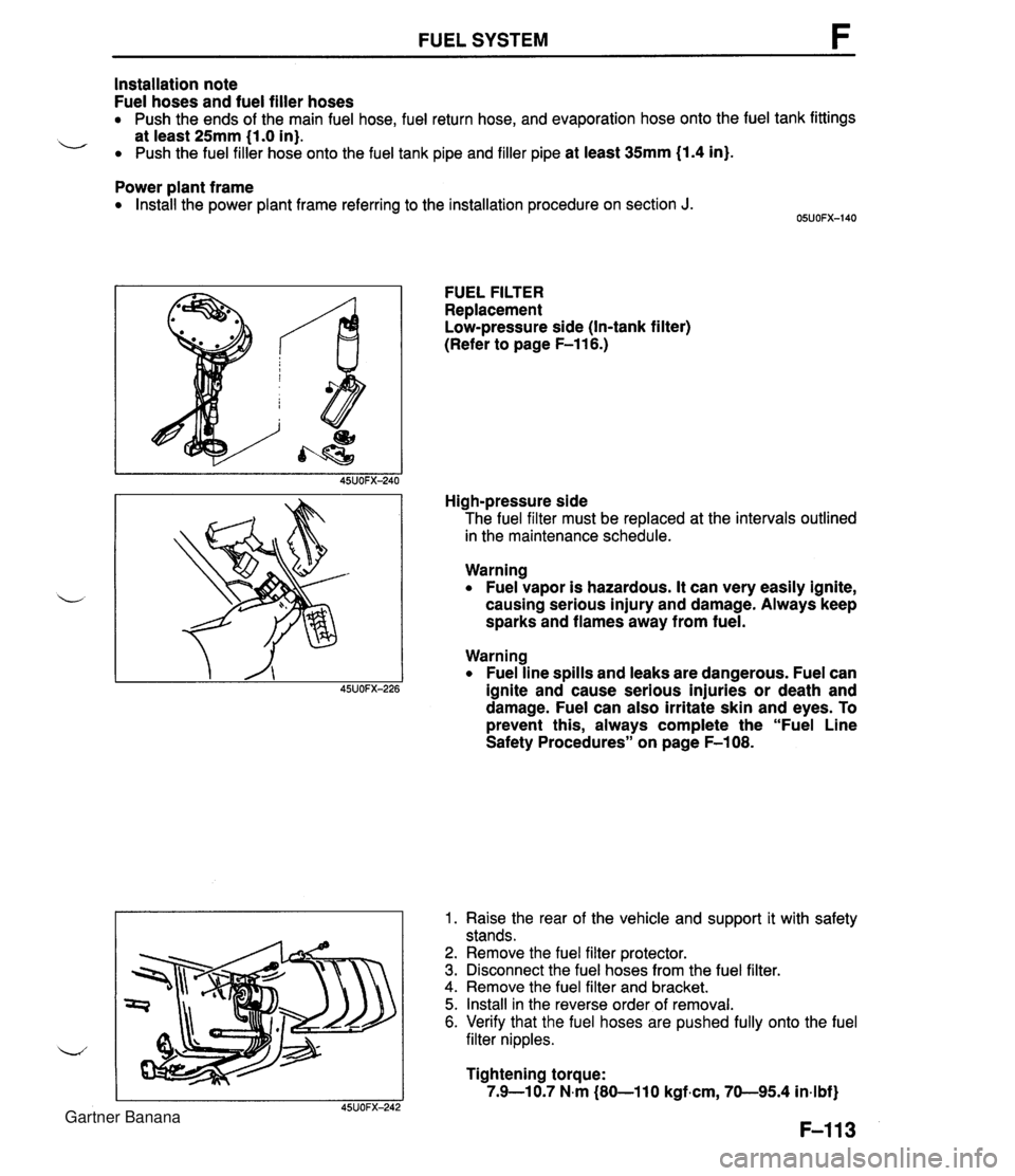
FUEL SYSTEM Installation note Fuel hoses and fuel filler hoses Push the ends of the main fuel hose, fuel return hose, and evaporation hose onto the fuel tank fittings L at least 25mm (1.0 in). Push the fuel filler hose onto the fuel tank pipe and filler pipe at least 35117171 (1.4 in). Power plant frame Install the power plant frame referring to the installation procedure on section J. FUEL FILTER Replacement Low-pressure side (In-tank filter) (Refer to page F-116.) High-pressure side The fuel filter must be replaced at the intervals outlined in the maintenance schedule. Warning Fuel vapor is hazardous. It can very easily ignite, causing serious injury and damage. Always keep sparks and flames away from fuel. Warning Fuel line spills and leaks are dangerous. Fuel can ~SJOFX-226 ignite and cause serious injuries or death and damage. Fuel can also irritate skin and eyes. To prevent this, always complete the "Fuel Line Safety Procedures" on page F-108. 1. Raise the rear of the vehicle and support it with safety stands. 2. Remove the fuel filter protector. 3. Disconnect the fuel hoses from the fuel filter. 4. Remove the fuel filter and bracket. 5. Install in the reverse order of removal. 6. Verify that the fuel hoses are pushed fully onto the fuel filter nipples. Tightening torque: 7.9-10.7 N.m (80-110 kgfam, 70-95.4 in-lbf) Gartner Banana
Page 268 of 1708
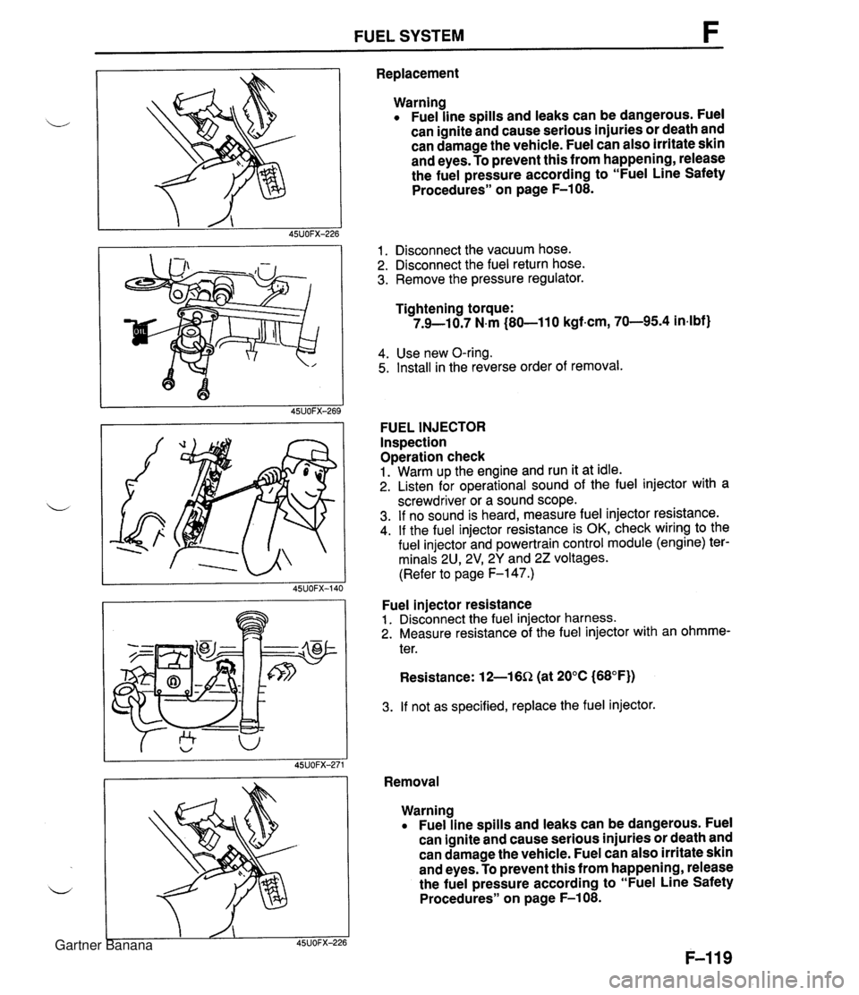
FUEL SYSTEM F Replacement Warning Fuel line spills and leaks can be dangerous. Fuel can ignite and cause serious injuries or death and can damage the vehicle. Fuel can also irritate skin and eyes. To prevent this from happening, release the fuel pressure according to "Fuel Line Safety Procedures" on page F-108. 1. Disconnect the vacuum hose. 2. Disconnect the fuel return hose. 3. Remove the pressure regulator. Tightening torque: 7.9-10.7 N.m (80-11 0 kgf-cm, 70-95.4 in4bf) 4. Use new O-ring. 5. Install in the reverse order of removal. FUEL INJECTOR Inspection Operation check 1. Warm up the engine and run it at idle. 2. Listen for operational sound of the fuel injector with a screwdriver or a sound scope. 3. If no sound is heard, measure fuel injector resistance. 4. If the fuel injector resistance is OK, check wiring to the fuel injector and powertrain control module (engine) ter- minals 2U, 2V1 2Y and 22 voltages. (Refer to page F-147.) Fuel injector resistance 1. Disconnect the fuel injector harness. 2. Measure resistance of the fuel injector with an ohmme- ter. Resistance: 12-16Q (at 20°C (68°F)) 3. If not as specified, replace the fuel injector. Removal Warning Fuel line spills and leaks can be dangerous. Fuel can ignite and cause serious injuries or death and can damage the vehicle. Fuel can also irritate skin and eyes. To prevent this from happening, release the fuel pressure according to "Fuel Line Safety Procedures" on page F-108. Gartner Banana
Page 270 of 1708
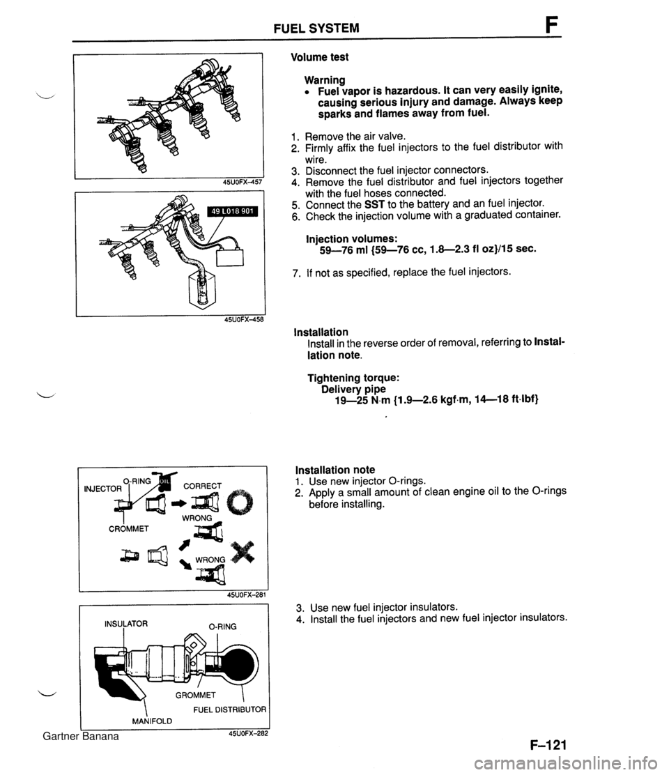
FUEL SYSTEM Volume test Warning Fuel vapor is hazardous. It can very easily ignite, causing serious injury and damage. Always keep sparks and flames away from fuel. 1. Remove the air valve. 2. Firmly affix the fuel injectors to the fuel distributor with wire. 3. Disconnect the fuel injector connectors. 4. Remove the fuel distributor and fuel injectors together with the fuel hoses connected. 5. Connect the SST to the battery and an fuel injector. 6. Check the injection volume with a graduated container. Injection volumes: 59-76 ml (59-76 cc, 1.8-2.3 fl oz}/15 sec. 7. If not as specified, replace the fuel injectors. lnstallation Install in the reverse order of removal, referring to Instal- lation note. Tightening torque: Delivery pipe 19-25 N.m (1 .%2.6 kgfm, 14--18 ft4bf) FUEL DISTRIBUTOR MANIFOLD C 45UOFX-282 Installation note 1. Use new injector O-rings. 2. Apply a small amount of clean engine oil to the O-rings before installing. 45UOFX-281 INSULATOR O-RING 3. Use new fuel injector insulators. 4. Install the fuel injectors and new fuel injector insulators. Gartner Banana
Page 301 of 1708
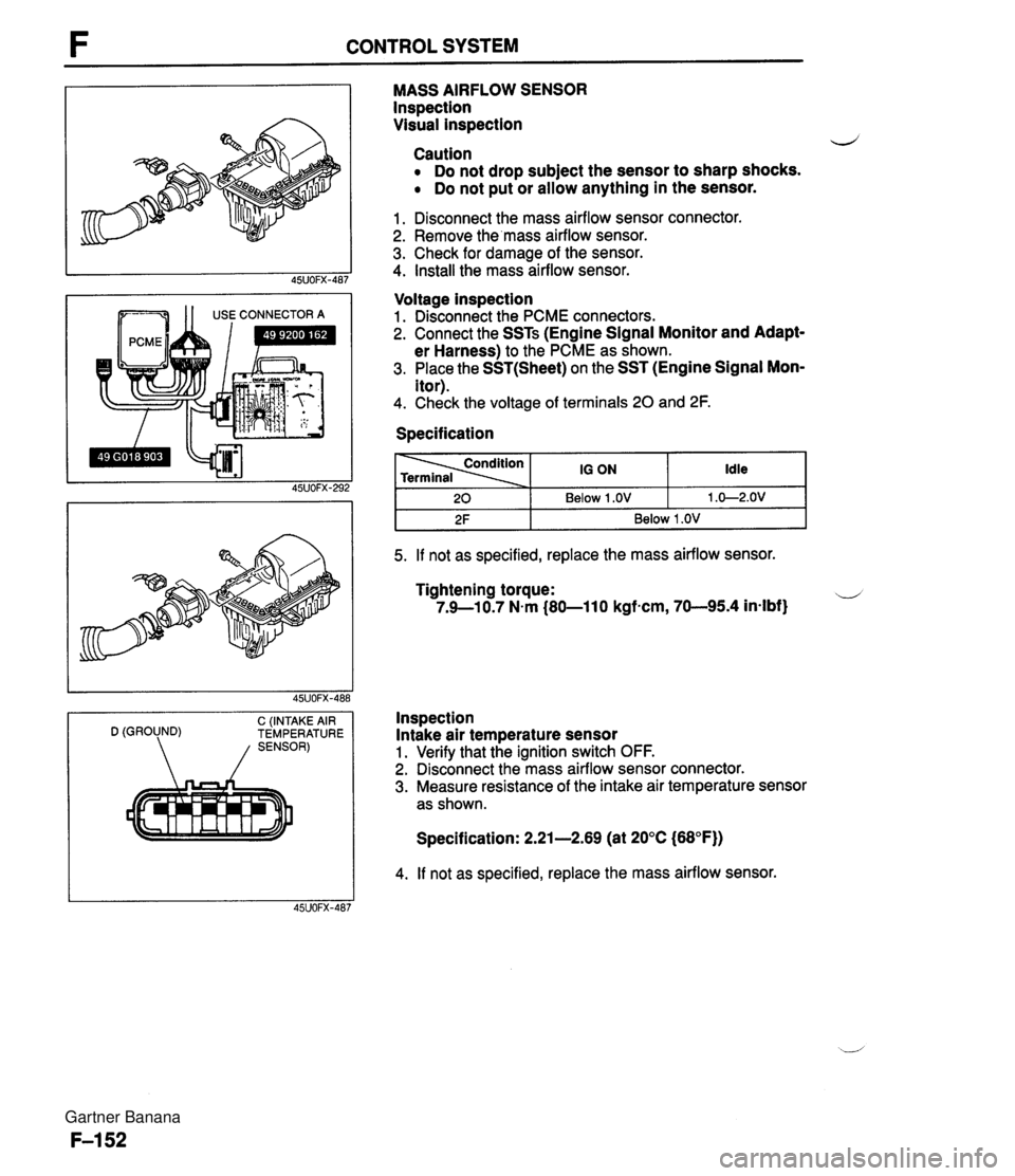
CONTROL SYSTEM --- 1 1 USE CONNECTOR A C (INTAKE AIR D (GROUND) TEMPERATURE MASS AIRFLOW SENSOR lnspection Visual inspection d Caution Do not drop subject the sensor to sharp shocks. Do not put or allow anything in the sensor. 1. Disconnect the mass airflow sensor connector. 2. Remove the'mass airflow sensor. 3. Check for damage of the sensor. 4. Install the mass airflow sensor. Voltage inspection 1. Disconnect the PCME connectors. 2. Connect the SSTs (Engine Signal Monitor and Adapt- er Harness) to the PCME as shown. 3. Place the SST(Sheet) on the SST (Engine Signal Mon- itor). 4. Check the voltage of terminals 20 and 2F. Specification I 2F I Below 1 .OV I 5. If not as specified, replace the mass airflow sensor. Idle 1 .O-2.OV 20 Tightening torque: u 7.9--10.7 N.m (80-11 0 kgfncm, 70-95.4 in-lbf} 10 ON Below 1 .OV Inspection Intake air temperature sensor 1. Verify that the ignition switch OFF. 2. Disconnect the mass airflow sensor connector. 3. Measure resistance of the intake air temperature sensor as shown. Specification: 2.21-2.69 (at 20°C (68°F)) 4. If not as specified, replace the mass airflow sensor. Gartner Banana
Page 302 of 1708
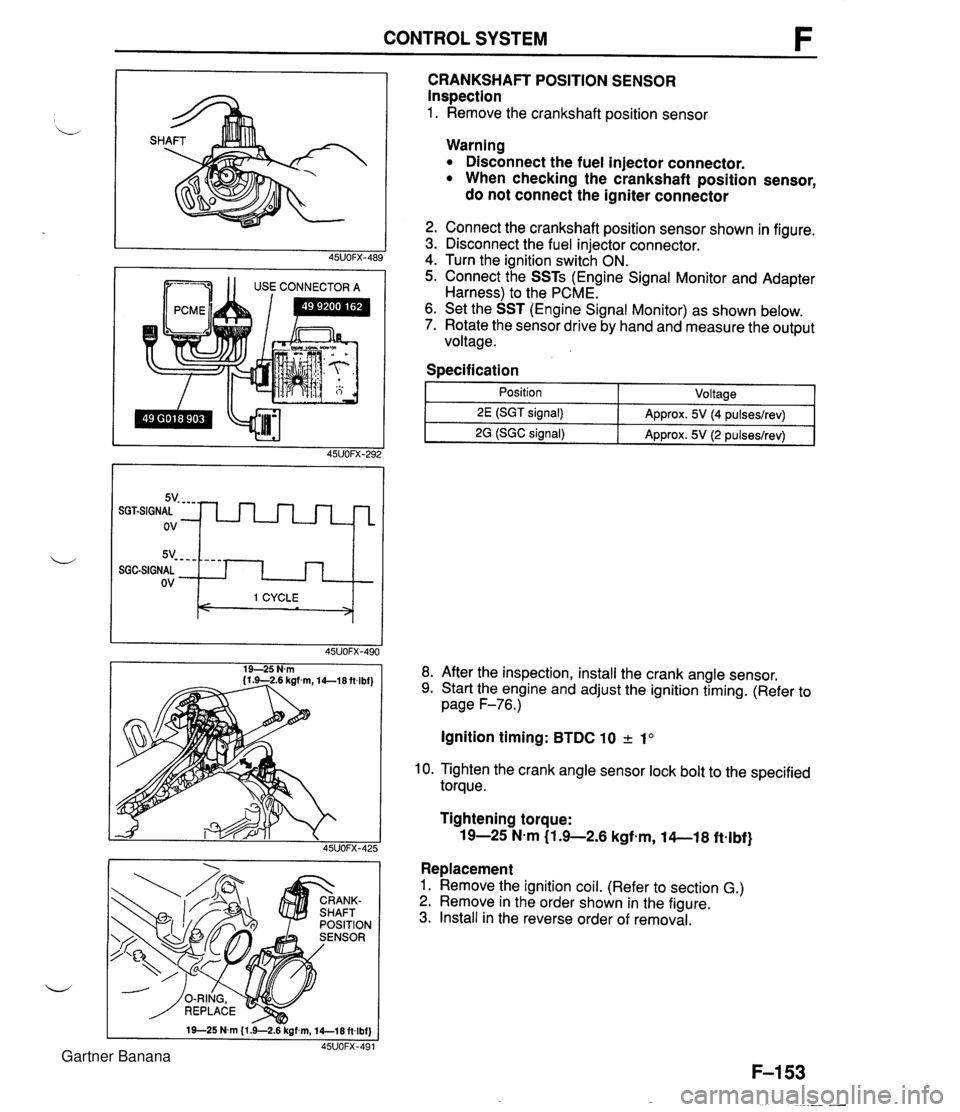
CONTROL SYSTEM 1 1 USE CONNECTOR A CRANKSHAFT POSITION SENSOR Inspection 1. Remove the crankshaft position sensor 5v- - - - SGGSIGNAL ov Warning Disconnect the fuel injector connector. When checking the crankshaft position sensor, do not connect the igniter connector - - - - I 1 CYCLE < > 2. Connect the crankshaft position sensor shown in figure. 3. Disconnect the fuel injector connector. 4. Turn the ignition switch ON. 5. Connect the SSTs (Engine Signal Monitor and Adapter Harness) to the PCME. 6. Set the SST (Engine Signal Monitor) as shown below. 7. Rotate the sensor drive by hand and measure the output voltage. Specification I 1 - Position - ~oltaael 8. After the inspection, install the crank angle sensor. 9. Start the engine and adjust the ignition timing. (Refer to page F-76.) 2E (SGT signal) 2G (SGC signal) Ignition timing: BTDC 10 2 1" Approx. 5V (4 pulseslrev) Approx. 5V (2 pulseslrev) 10. Tighten the crank angle sensor lock bolt to the specified torque. Tightening torque: 19-25 N-m (1 .+2.6 kgfem, 14-1 8 ftelbf} Replacement 1. Remove the ignition coil. (Refer to section G.) 2. Remove in the order shown in the figure. 3. Install in the reverse order of removal. Gartner Banana
Page 303 of 1708
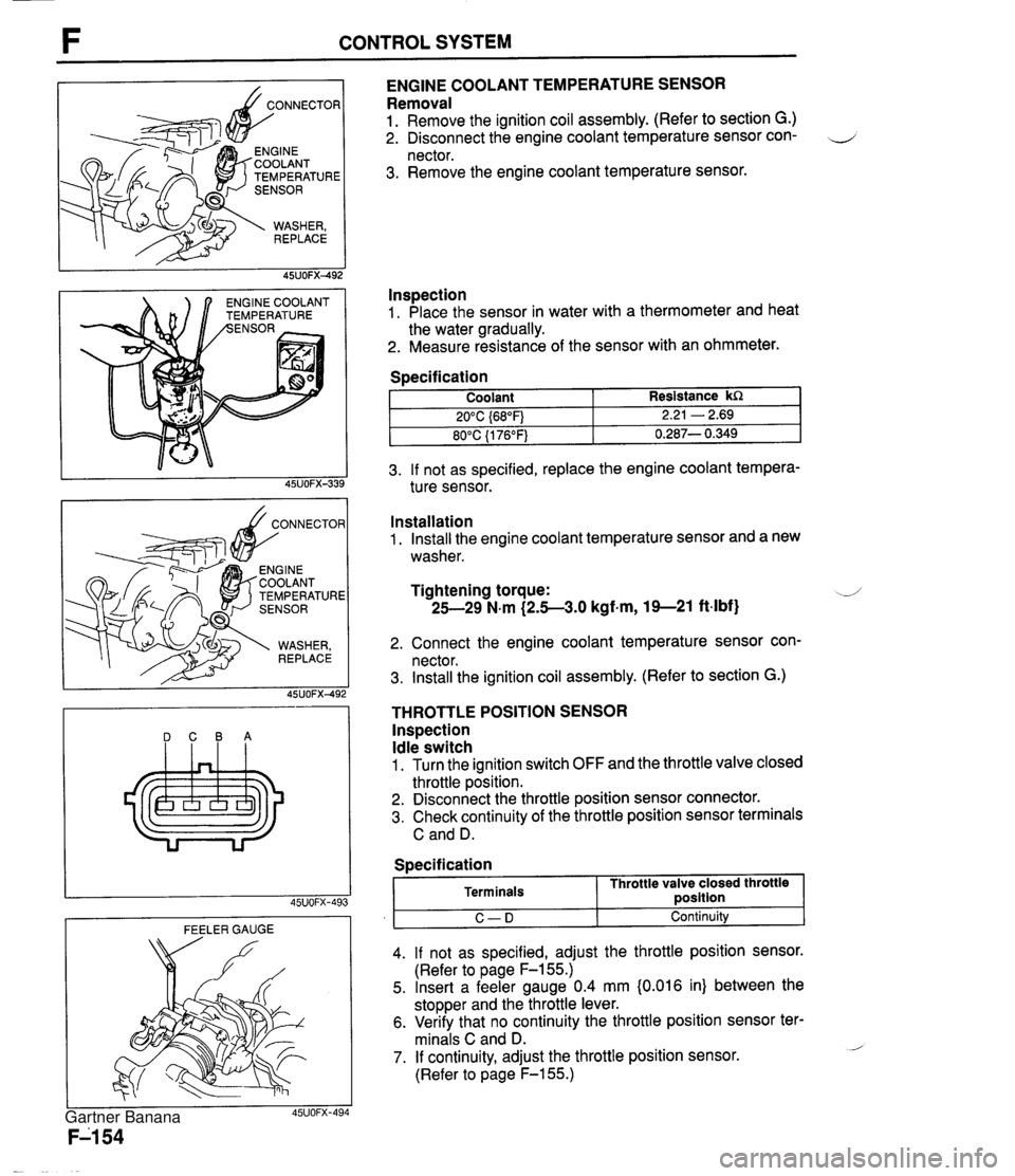
CONTROL SYSTEM TEMPERATURE NGlNE COOLANT EMPERATURE ENGINE COOLANT TEMPERATURE SENSOR Removal 1. Remove the ignition coil assembly. (Refer to section G.) 2. Disconnect the engine coolant temperature sensor con- 4 nector. 3. Remove the engine coolant temperature sensor. lnspection 1. Place the sensor in water with a thermometer and heat the water gradually. 2. Measure resistance of the sensor with an ohmmeter. 3. If not as specified, replace the engine coolant tempera- ture sensor. Specification DCBA Coolant 20°C {68"F) 80°C {I 76°F) FEELER GAUGE Resistance kR 2.21 - 2.69 0.287- 0.349 Installation 1. Install the engine coolant temperature sensor and a new washer. Tightening torque: -J 25-29 N.m (2.5-3.0 kgf-m, 19--21 ft-lbf) 2. Connect the engine coolant temperature sensor con- nector. 3. Install the ignition coil assembly. (Refer to section G.) THROTTLE POSITION SENSOR lnspection Idle switch 1. Turn the ignition switch OFF and the throttle valve closed throttle position. 2. Disconnect the throttle position sensor connector. 3. Check continuity of the throttle position sensor terminals C and D. I C-D I Continuity 4. If not as specified, adjust the throttle position sensor. (Refer to page F-155.) 5. Insert a feeler gauge 0.4 mm {0.016 in) between the stopper and the throttle lever. 6. Verify that no continuity the throttle position sensor ter- minals C and D. - 7. If continuity, adjust the throttle position sensor. (Refer to page F-155.) Specification Terminals Throttle valve closed throttle ~osition Gartner Banana