Page 320 of 1708
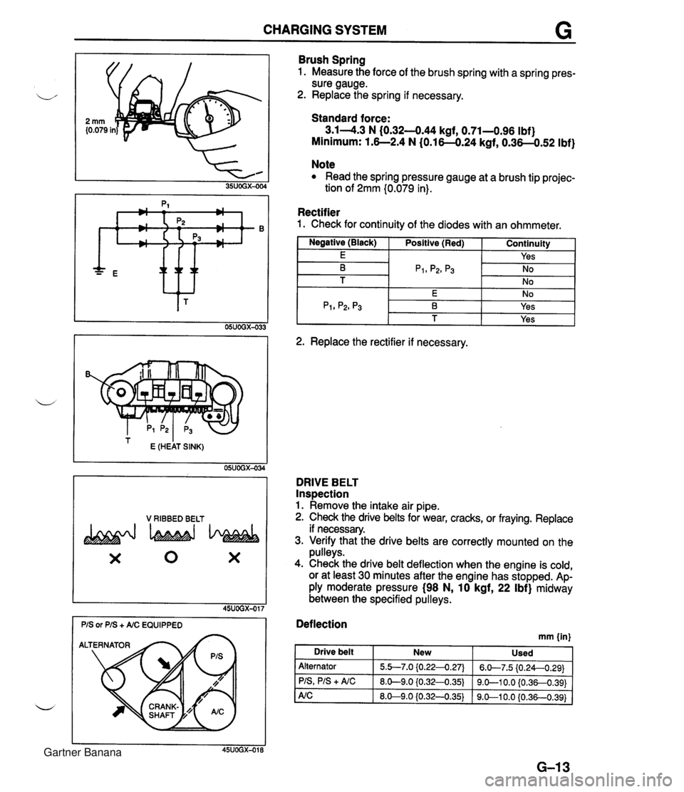
CHARGING SYSTEM G * ttt I E (HEAT SINK) 05UOGX-034 V RIBBED BELT X 0 X Brush Spring 1. Measure the force of the brush spring with a spring pres- sure gauge. 2. Replace the spring if necessary. Standard force: 3.14.3 N (0.32-444 kgf, 0.71-0.96 Ibf) Minimum: 1.6--2.4 N (0.16-0.24 kgf, 0.36-0.52 Ibf) Note Read the spring pressure gauge at a brush tip projec- tion of 2mm (0.079 in). Rectifier 1. Check for continuity of the diodes with an ohmmeter. I Negative (Black) I Positive (Red) I Continuity 1 I E I I Yes I -- 2. Replace the rectifier if necessary. DRIVE BELT Inspection 1. Remove the intake air pipe. 2. Check the drive belts for wear, cracks, or fraying. Replace if necessary. 3. Verify that the drive belts are correctly mounted on the pulleys. 4. Check the drive belt deflection when the engine is cold, or at least 30 minutes after the engine has stopped. Ap- ply moderate pressure (98 N, 10 kgf, 22 Ibf) midway between the specified pulleys. Deflection mm {in) I Drive belt New Used Alternator PIS, PIS + A/C 5.b7.0 {0.224.27) 8.0-9.0 iO.32-0.35) 6.W7.5 (0.24--0.29) 9.0-1 0.0 {0.36-0.391 Gartner Banana
Page 321 of 1708
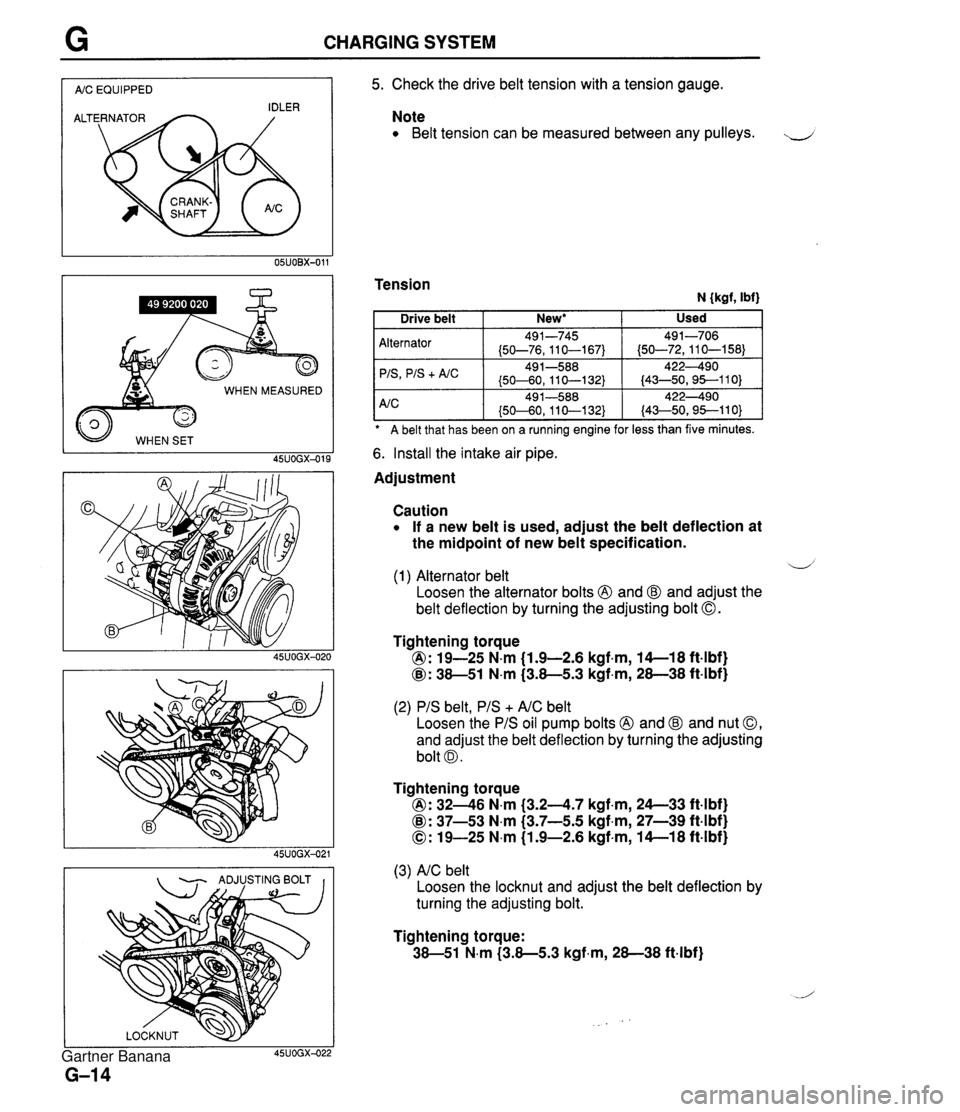
CHARGING SYSTEM I AIC EQUIPPED I WHEN MEASURED 45UOGX-015 - ADJUSTING BOLT I I 5. Check the drive belt tension with a tension gauge. Note Belt tension can be measured between any pulleys. J Tension N {kgf, Ibf) A belt that has been on a ruining engine for less than five minutes. Alternator 'IS
+ A/C 6. Install the intake air pipe. Used Drive belt Adjustment New* I Caution If a new belt is used, adjust the belt deflection at the midpoint of new belt specification. 491-745 (50-76,110-167) 49 1-588 (50-60, 11 0-1 32) d (1) Alternator belt Loosen the alternator bolts @ and @ and adjust the belt deflection by turning the adjusting bolt 0. 491-706 (50-72,110-158) 422490 (43-50,95--110) Tightening torque @: 19-25 N.m (1.9-2.6 kgf.m, 14-1 8 ft4bf) @: 38-51 N.m (3.8-5.3 kgf,m, 28-38 ft-lbf) (2) PIS belt, PIS + AIC belt Loosen the PIS oil pump bolts @ and @ and nut 0, and adjust the belt deflection by turning the adjusting bolt 0. Tightening torque @: 3246 N.m (3.24.7 kgf.m, 24--33 ft4bf) @: 37-53 N.m (3.7-5.5 kgf,m, 27-39 ft-lbf) 0: 19-25 N.m (1.9-2.6 kgf-m, 14-1 8 ft-lbf) (3) AIC belt Loosen the locknut and adjust the belt deflection by turning the adjusting bolt. Tightening torque: 38-51 N.m (3.8-5.3 kgf-m, 28-38 ft-lbf) Gartner Banana
Page 324 of 1708
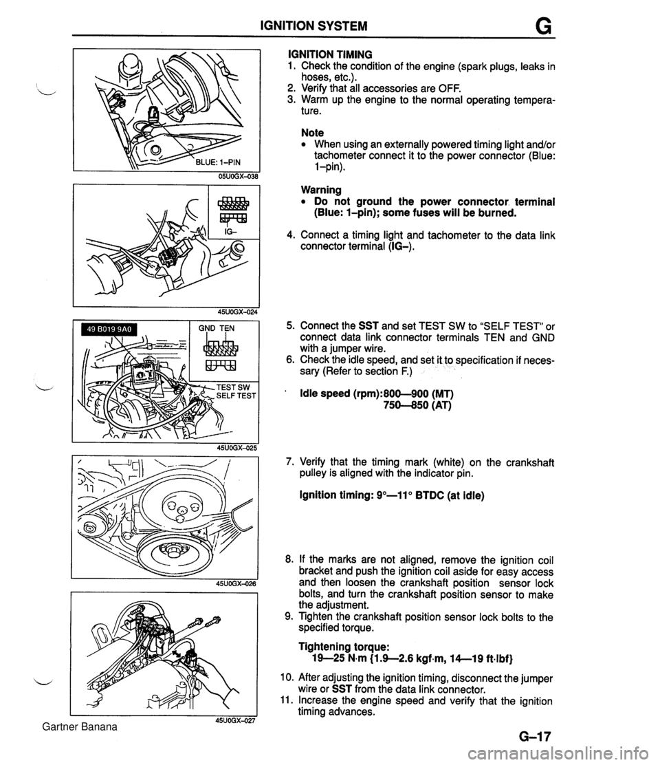
IGNITION SYSTEM G GND TEN I I I IGNITION TIMING 1. Check the condition of the engine (spark plugs, leaks in hoses, etc.). 2. Verify that all accessories are OFF. 3. Warm up the engine to the normal operating tempera- ture. Note When using an externally powered timing light and/or tachometer connect it to the power connector (Blue: l-pin). Warning Do not ground the power connector. terminal (Blue: l-pin); some fuses will be burned. 4. Connect a timing light and tachometer to the data link connector terminal (IG-). 5. Connect the SST and set TEST SW to "SELF TEST" or connect data link connector terminals TEN and GND with a jumper wire. 6. Check the idle speed, and set it to specification if neces- sary (Refer to section F.) ' Idle speed (rpm):800-900 (MT) 75-50 (AT) 7. Verify that the timing mark (white) on the crankshaft pulley is aligned with the indicator pin. Ignition timing: 9"-11" BTDC (at idle) 8. If the marks are not aligned, remove the ignition coil bracket and push the ignition coil aside for easy access and then loosen the crankshaft position sensor lock bolts, and turn the crankshaft position sensor to make the adjustment. 9. Tighten the crankshaft position sensor lock bolts to the specified torque. Tightening torque: 19-25 N-m (1 3-2.6 kgf~m, l4--19 ft.lbf) 10. After adjusting the ignition timing, disconnect the jumper wire or SST from the data link connector. 11. Increase the engine speed and verify that the ignition timing advances. Gartner Banana
Page 325 of 1708
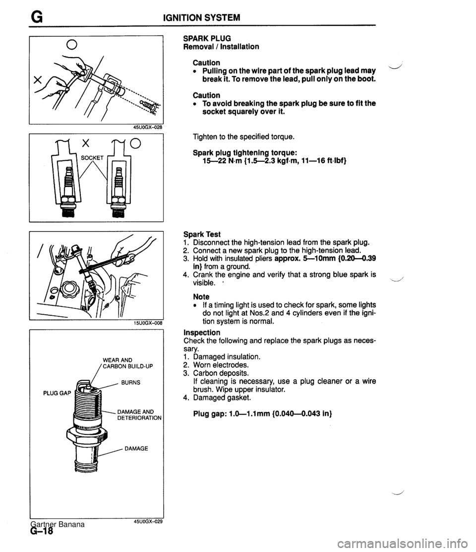
G IGNITION SYSTEM BURNS PLUG GAP DAMAGE AND DETERIORATION DAMAGE SPARK PLUG Removal 1 Installation Caution Pulling on the wire part of the spark plug lead may i/ break it. To remove the lead, pull only on the boot. Caution To avoid breaking the spark plug be sure to fit the socket squarely over it. Tighten to the specified torque. Spark plug tightening torque: 15--22 N-m (1.5--2.3 kgf-m, 11-16 ft-lbf) Spark Test 1. Disconnect the high-tension lead from the spark plug. 2. Connect a new spark plug to the high-tension lead. 3. Hold with insulated pliers approx. 5-10mm (0.20-4.39 in) from a ground. 4. Crank the engine and verify that a strong blue spark is visible. . -.d' Note If a timing light is used to check for spark, some lights do not light at Nos.:! and 4 cylinders even if the igni- tion system is normal. Inspection Check the following and replace the spark plugs as neces- sary. 1. Damaged insulation. 2. Worn electrodes. 3. Carbon deposits. If cleaning is necessary, use a plug cleaner or a wire brush. Wipe upper insulator. 4. Damaged gasket. Plug gap: 1 .O-1 .l mm (0.040-0.043 in) Gartner Banana
Page 338 of 1708
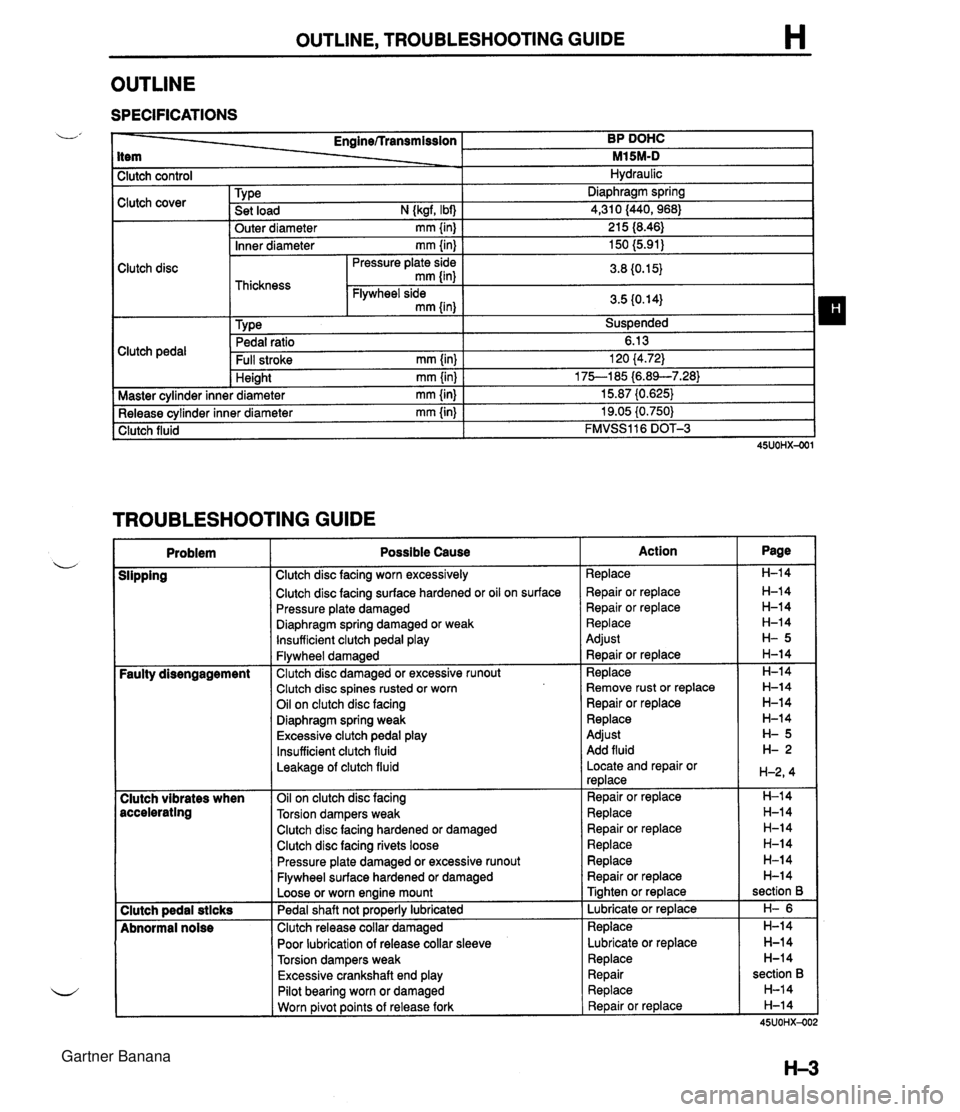
OUTLINE, TROUBLESHOOTING GUIDE H OUTLINE SPECIFICATIONS I Clutch control L' Clutch cover Clutch disc Clutch pedal - Enginerrransmission BP DOHC item - M15M-D 1 Master cvlinder inne I Hydraulic Inner diameter mm {in) I 150 (5.91) I Pressure plate side I n n rn cr Tvpe . . Set load N {kgf, Ibf) Outer diameter mm {in) Pedal ratio 6.13 Full stroke mm {in) I 120 (4.72) Diaphraam spring .-.- 4,310 (440,968) 21 5 18.46) . - Height mm {in) * diameter mm {in) TROUBLESHOOTING GUIDE . - I 75--185 i6.89--7.283 15.87 (0.625) . - Release cylinder inner diameter mm {in) Clutch fluid I Problem I Possible Cause 19.05 i0.750) FMVSS116 DOT-3 Clutch disc facing surface hardened or oil on surface Pressure plate damaged u Diaphragm spring damaged or weak lnsufficient clutch pedal play I Slipping I Clutch disc facing worn excessively I Flywheel damaged Faulty disengagement I Clutch disc damaged or excessive runout Clutch disc spines rusted or worn Oil on clutch disc facing Diaphragm spring weak Excessive clutch pedal play Insufficient clutch fluid Leakage of clutch fluid I 1 Clutch disc facing hardened or damaged Clutch vibrates when accelerating I I Clutch disc facing rivets loose Oil on clutch disc facing Torsion dampers weak Clutch pedal stlcks Abnormal noise Pressure plate damaged or excessive runout Flywheel surface hardened or damaged Loose or worn engine mount Pedal shaft not pro~erlv lubricated Clutch release collar damaged Poor lubrication of release collar sleeve Torsion dampers weak Excessive crankshaft end play I I Pilot bearing worn or damaged I I Worn ~ivot points of release fork Action Replace Repair or replace Repair or replace Replace Adjust ~ebair or replace Replace Remove rust or replace Repair or replace Replace Adjust Add fluid Locate and repair or replace Repair or replace Replace Repair or replace Replace Replace Repair or replace Tighten or replace Lubricate or replace Replace Lubricate or replace Replace Repair Replace Repair or replace Page H-14 H-14 H-14 H-14 H-14 H-14 section B H- 6 H-14 H-14 H-14 section B H-14 H-14 45UOHX-OC Gartner Banana
Page 366 of 1708
J TRANSMISSION Caution Removing the PPF spacers will reduce the perfor- mance of the PPF. If the spacers are removed, replace the PPF as an assembly. 10. Remove the transmission-side bolts, and remove the PPF. Transmission 1. Support the transmission with a transmission jack. 2. Loosen the transmission installation bolts. Caution Shaking the transmission could damage the crank angle sensor on the engine. When remov- ing the transmission, do not shake it up and down or side to side. 3. Remove the transmission. 45uOJx-007 Gartner Banana
Page 399 of 1708
TRANSMISSION J INSTALLATION 1. On level ground, jack up the vehicle and support it evenly on safety stands. 2. Install in the order shown in the figure, referring to lnstallation Note. L 3. Add the specified amount of the specified transmission oil. (Refer to page J-8.) 4. Warm up the engine and transmission, and inspect for oil leakage and transmission problems. 1. Transmission 7. Exhaust pipe Installation Note ............. page J-46 8. Performance rod 2. Power plant frame (PPF) 9. Differential mounting pipe Installation Note ............. page J-46 10. Undercover 3. S~eedometer cable 11. Shift lever w 4. ~iarter Installation Note ............. page J-47 5. Clutch release cylinder 12. Rear console 6. Propeller shaft 13. Shift lever knob Service ...................... section L Gartner Banana
Page 400 of 1708
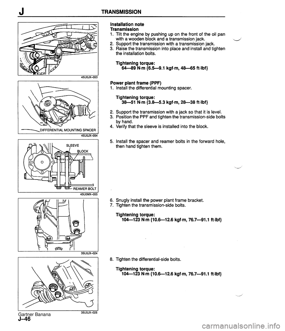
J TRANSMISSION -=DIFFERENTIAL MOUNTING SPACER 45UOJX-054 Installation note Transmission 1. Tilt the engine by pushing up on the front of the oil pan with a wooden block and a transmission jack. d 2. Support the transmission with a transmission jack. 3. Raise the transmission into place and install and tighten the installation bolts. Tightening torque: 64-89 N-m (6.5--9.1 kgf-m, 48-65 ft.lbf) Power plant frame (PPF) 1. Install the differential mounting spacer. Tightening torque: 38-51 N.m (3.8-5.3 kgf-m, 28-38 ft-lbf) 2. Support the transmission with a jack so that it is level. 3. Position the PPF and tighten the transmission-side bolts by hand. 4. Verify that the sleeve is installed into the block. 5. Install the spacer and reamer bolts in the forward hole, then hand tighten them. 6. Snugly install the power plant frame bracket. 7. Tighten the transmission-side bolts. Tightening torque: 104-123 N-m (10.S12.6 kgf.m, 76.7-91.1 ft.lbf) 8. Tighten the differential-side bolts. Tightening torque: 104-1 23 N-m (1 0.S12.6 kgf.m, 76.7-91.1 ft-lbf) Gartner Banana