Page 1012 of 1708

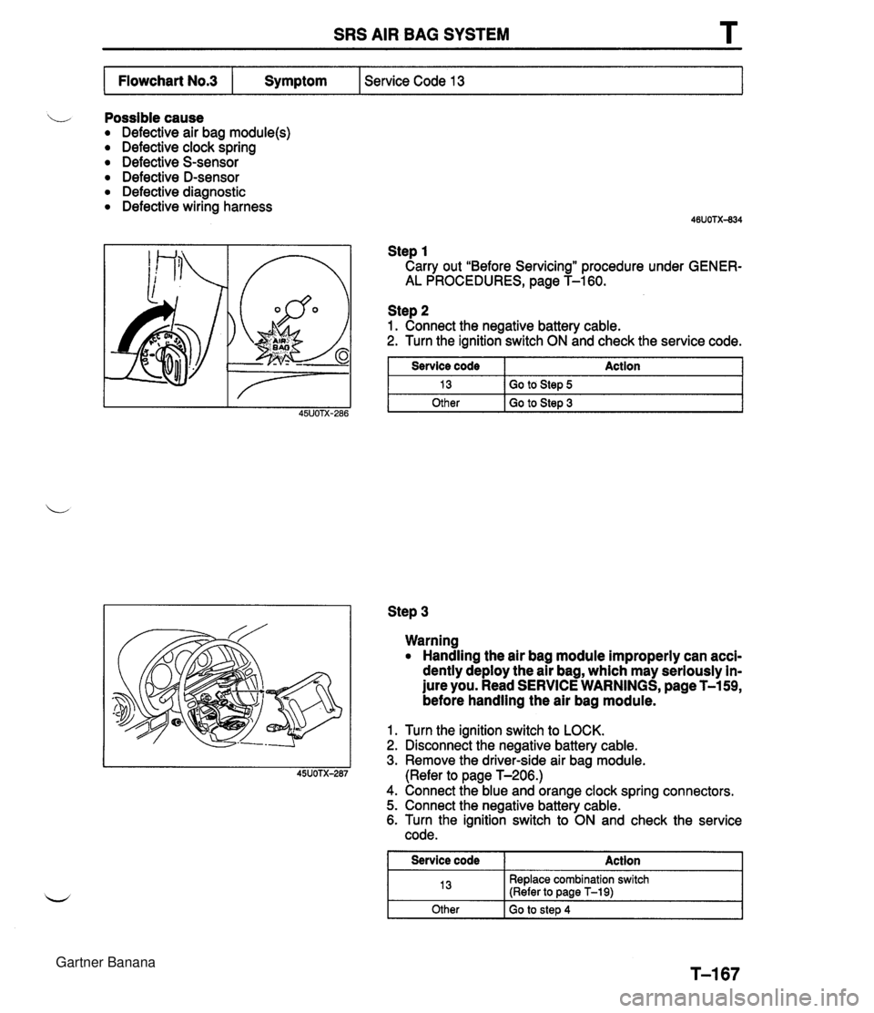
SRS AIR BAG SYSTEM L Possible cause Defective air bag module(s) Defective clock spring Defective S-sensor Defective D-sensor Defective diagnostic Defective wiring harness Step 1 Carry out "Before Servicing" procedure under GENER- AL PROCEDURES, page T-160. Service Code 13 Flowchart No.3 Step 2 1. Connect the negative battery cable. 2. Turn the ignition switch ON and check the service code. Symptom Step 3 Service code 13 Other Warning Handling the air bag module improperly can acci- dently deploy the air bag, which may seriously in- jure you. Read SERVICE WARNINGS, page T-159, before handling the air bag module. Action Go to Step 5 Go to Step 3 1. Turn the ignition switch to LOCK. 2. Disconnect the negative battery cable. 3. Remove the driver-side air bag module. (Refer to page T-206.) 4. Connect the blue and orange clock spring connectors. 5. Connect the negative battery cable. 6. Turn the ignition switch to ON and check the service code. I Service code I Action 1 13 Other Replace combination switch (Refer to page T-19) Go to step 4 Gartner Banana
Page 1013 of 1708

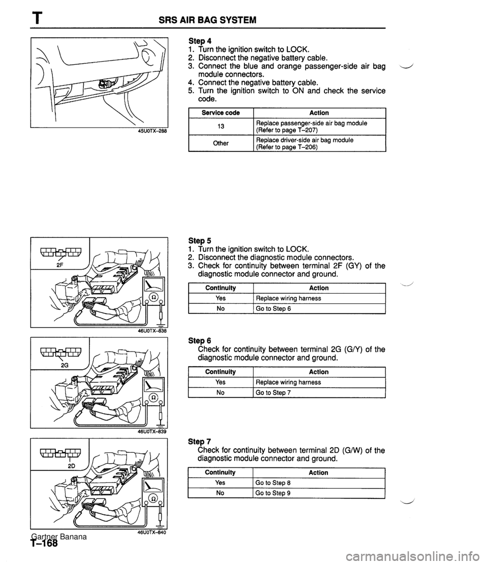
T SRS AIR BAG SYSTEM Step 4 1. Turn the ignition switch to LOCK. 2. Disconnect the negative battery cable. 3. Connect the blue and orange passenger-side air bag d module connectors. 4. Connect the negative battery cable. 5. Turn the ignition switch to ON and check the service code. I Service code I Action I I 13 Replace passenger-side air bag module (Refer to page T-207) I I mer I Replace driver-side air bag module (Refer to ~aae T-2061 I No I Go to Step 6 Step 5 1. Turn the ignition switch to LOCK. 2. Disconnect the diagnostic module connectors. 3. Check for continuity between terminal 2F (GY) of the diagnostic module connector and ground. Step 6 Check for continuity between terminal 2G (GN) of the diagnostic module connector and ground. I Continuity Action d Continuity Yes Step 7 Check for continuity between terminal 20 (GNV) of the diagnostic module connector and ground. Action Replace wiring harness Yes No Replace wiring harness Go to Step 7 I NO I GO to Step 9 ~d Continuity Yes Action Go to Step 8 Gartner Banana
Page 1014 of 1708
SRS AIR BAG SYSTEM Step 8 1. Disconnect the orange and blue S-sensor connectors. 2. Check for continuity between terminal C of the S-sensor and ground. Continuity Action 1 Yes No Step 10 1. Disconnect the suspect sensor connector. 2. Measure the resistance between terminal A of the sen- sor and ground. Replace S-sensor (Refer to page T-213) Replace wiring harness Step 9 Measure the resistance between terminal 1 C (BRIG), 1 A (BRIR), and 2L (BRIB) of the diagnostic module connec- tor and ground. Resistance k&2 Other Other I Replace sensor I Action Replace diagnostic module (Refer to page T-208) Suspect sensor: Terminal 1 C -+ right D-sensor Terminal 1 A -+ Center D-sensor Terminal 2L -+ left D-sensor Go to Step 10 Measure 1.18 kn Action Replace wiring harness Gartner Banana
Page 1015 of 1708
T SRS AIR BAG SYSTEM Possible cause i/ Defective S-sensor Defective wiring harness Defective diagnostic module Step 1 Carry out "Before Servicing" procedure under GENER- AL PROCEDURES, page T-160. Service Code 21 Flowchart No.4 Step 2 1. Disconnect the diagnostic module connector. 2. Check for continuity between terminal 1 E (RIB) of the Symptom connector and ground. Step 3 1. -Disconnect the orange and blue S-sensor connector. 2. Check for continuity between terminal A of the S-sensor and ground. I Continuity I Action Continuity Yes No Action Replace diagnostic module (Refer to page T-208) Go to Step 3 Yes No Replace wiring harness Replace S-sensor (Refer to page T-213) Gartner Banana
Page 1016 of 1708
SRS AIR BAG SYSTEM T Flowchart N0.5 I Symptom I Service Code 22 Possible cause Defective wiring harness Defective S-sensor Defective diagnostic module Step 1 Carry out "Before Servicing" procedure under GENER- AL PROCEDURES, page T-160. Step 2 1. Disconnect the diagnostic module connector. 2. Check for continuity between terminal 1 H (GIB) and 2D (GMI) of the diagnostic module connector. Continuity Yes Step 3 1. Disconnect the orange and blue S-sensor connectors. 2. Check for continuity between terminal B and D of the S- sensor. Continuity I Action I Action Go to Step 3 I No Replace diagnostic module (Refer to page T-208) Yes No Replace S-sensor (Refer to page T-213) Replace wiring harness Gartner Banana
Page 1017 of 1708
T SRS AIR BAG SYSTEM Possible cause Defective wiring harness Defective S-sensor Defective diagnostic module Step 1 Carry out "Before Servicing" procedure under GENER- AL PROCEDURES, page T-160. Service Code 23 Flowchart No.6 Step 2 1. Disconnect the diagnostic module connector. 2. Check for continuity between terminal 1 H (GIB) and 2C (G) of the diagnostic module connector. Symptom I No Go to Step 3 Continuity Yes Step 3 1. Disconnect orange and blue S-sensor connectors. 2. Check for continuity between terminal B and E of the S- sensor. Action Replace diagnostic module (Refer to pane T-208) No I Replace S-sensor (Refer to page T-213) I Continuity Yes Action Replace wiring harness Gartner Banana
Page 1018 of 1708
SRS AIR BAG SYSTEM T i/ Possible cause Open circuit in wiring harness Damaged diagnostic module Flowchart No.7 Step 1 Carry out "Before Servicing" procedure under GENER- AL PROCEDURES, page T-160. Step 2 1. Disconnect the diagnostic module connector. 2. Check for continuity between terminal 2B (GNV) and 20 (GNV) of the diagnostic module connector. Symptom Continuity Action I Service Code 24 I Yes Replace diagnostic module (Refer to Daae T-208) - -- No I Replace wiring harness Gartner Banana
Page 1019 of 1708

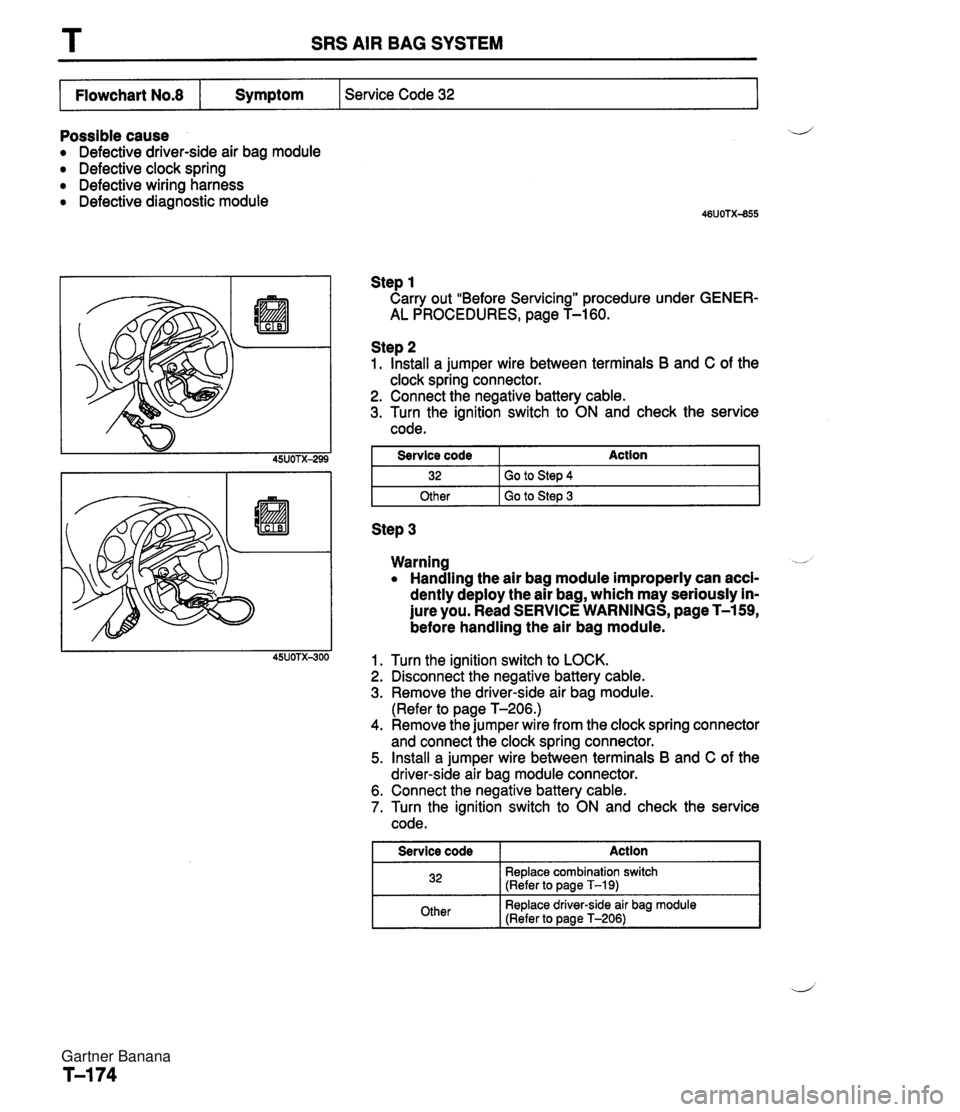
T SRS AIR BAG SYSTEM I Flowchart No.8 I Symptom I Service Code 32 I Possible cause a Defective driver-side air bag module a Defective clock spring Defective wiring harness a Defective diagnostic module Step 1 Carry out "Before Servicing" procedure under GENER- AL PROCEDURES, page T-160. Step 2 1. Install a jumper wire between terminals B and C of the clock spring connector. 2. Connect the negative battery cable. 3. Turn the ignition switch to ON and check the service code. I Other I Go to Step 3 I Service code 32 Step 3 Action Go to Step 4 Warning -- a Handling the air bag module improperly can acci- dently deploy the air bag, which may seriously in- jure you. Read SERVICE WARNINGS, page T-159, before handling the air bag module. Turn the ignition switch to LOCK. Disconnect the negative battery cable. Remove the driver-side air bag module. (Refer to page T-206.) Remove the jumper wire from the clock spring connector and connect the clock spring connector. Install a jumper wire between terminals B and C of the driver-side air bag module connector. Connect the negative battery cable. Turn the ignition switch to ON and check the service code. I Service code Action I 32 Replace combination switch (Refer to page T-19) Other Replace driver-side air bag module (Refer to page T-206) Gartner Banana