Page 302 of 1708

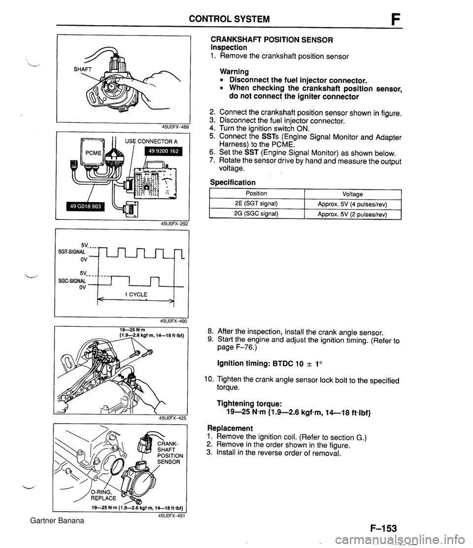
CONTROL SYSTEM 1 1 USE CONNECTOR A CRANKSHAFT POSITION SENSOR Inspection 1. Remove the crankshaft position sensor 5v- - - - SGGSIGNAL ov Warning Disconnect the fuel injector connector. When checking the crankshaft position sensor, do not connect the igniter connector - - - - I 1 CYCLE < > 2. Connect the crankshaft position sensor shown in figure. 3. Disconnect the fuel injector connector. 4. Turn the ignition switch ON. 5. Connect the SSTs (Engine Signal Monitor and Adapter Harness) to the PCME. 6. Set the SST (Engine Signal Monitor) as shown below. 7. Rotate the sensor drive by hand and measure the output voltage. Specification I 1 - Position - ~oltaael 8. After the inspection, install the crank angle sensor. 9. Start the engine and adjust the ignition timing. (Refer to page F-76.) 2E (SGT signal) 2G (SGC signal) Ignition timing: BTDC 10 2 1" Approx. 5V (4 pulseslrev) Approx. 5V (2 pulseslrev) 10. Tighten the crank angle sensor lock bolt to the specified torque. Tightening torque: 19-25 N-m (1 .+2.6 kgfem, 14-1 8 ftelbf} Replacement 1. Remove the ignition coil. (Refer to section G.) 2. Remove in the order shown in the figure. 3. Install in the reverse order of removal. Gartner Banana
Page 303 of 1708

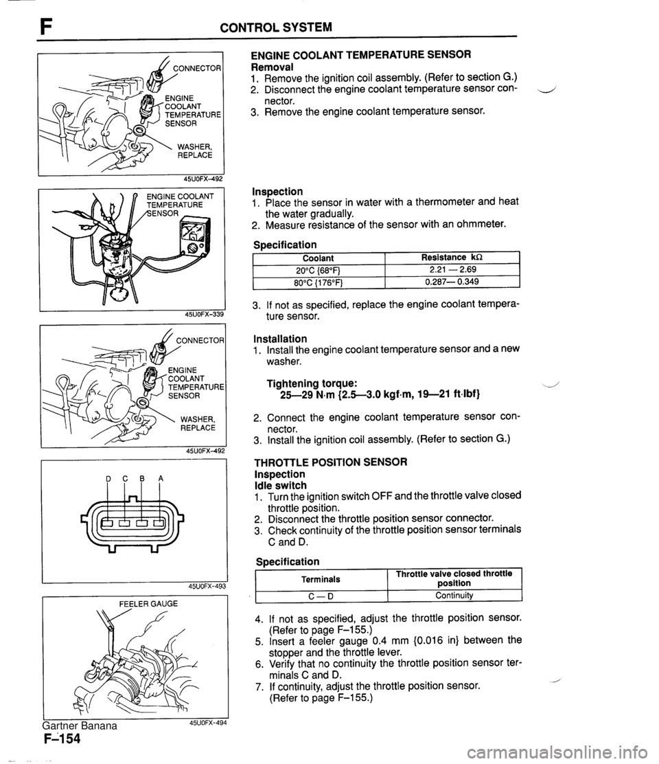
CONTROL SYSTEM TEMPERATURE NGlNE COOLANT EMPERATURE ENGINE COOLANT TEMPERATURE SENSOR Removal 1. Remove the ignition coil assembly. (Refer to section G.) 2. Disconnect the engine coolant temperature sensor con- 4 nector. 3. Remove the engine coolant temperature sensor. lnspection 1. Place the sensor in water with a thermometer and heat the water gradually. 2. Measure resistance of the sensor with an ohmmeter. 3. If not as specified, replace the engine coolant tempera- ture sensor. Specification DCBA Coolant 20°C {68"F) 80°C {I 76°F) FEELER GAUGE Resistance kR 2.21 - 2.69 0.287- 0.349 Installation 1. Install the engine coolant temperature sensor and a new washer. Tightening torque: -J 25-29 N.m (2.5-3.0 kgf-m, 19--21 ft-lbf) 2. Connect the engine coolant temperature sensor con- nector. 3. Install the ignition coil assembly. (Refer to section G.) THROTTLE POSITION SENSOR lnspection Idle switch 1. Turn the ignition switch OFF and the throttle valve closed throttle position. 2. Disconnect the throttle position sensor connector. 3. Check continuity of the throttle position sensor terminals C and D. I C-D I Continuity 4. If not as specified, adjust the throttle position sensor. (Refer to page F-155.) 5. Insert a feeler gauge 0.4 mm {0.016 in) between the stopper and the throttle lever. 6. Verify that no continuity the throttle position sensor ter- minals C and D. - 7. If continuity, adjust the throttle position sensor. (Refer to page F-155.) Specification Terminals Throttle valve closed throttle ~osition Gartner Banana
Page 308 of 1708

Before beginning any service procedure. refer to section T of this manual for air bag system service warnings and audio antitheft system alarm conditions . ENGINE ELECTRICAL SYSTEM INDEX ....................................... G- 2 OUTLINE ..................................... G- 3 SPECIFICATIONS ........................... G- 3 TROUBLESHOOTING GUIDE .................. G- 4 CHARGING SYSTEM .......................... G- 6 PREPARATION ............................. G- 6 CIRCUIT DIAGRAM ......................... G- 6 TROUBLESHOOTING ....................... G- 7 BATTERY .................................. G- 8 ALTERNATOR .............................. G-10 DRIVE BELT ................................ G-13 IGNITION SYSTEM ............................ G-15 PREPARATION ............................. G-15 CIRCUIT DIAGRAM ......................... G-15 TROUBLESHOOTING ....................... G-16 IGNITION TIMING ........................... G-17 SPARK PLUG ............................... G-18 IGNITION COIL ............................. G-19 IGNITER ................................... G-19 HIGH-TENSION LEAD ....................... G-20 STARTING SYSTEM ........................... G-21 CIRCUIT DIAGRAM ......................... G-21 TROUBLESHOOTING ....................... G-21 STARTER .................................. G-22 STARTER INTERLOCK SWITCH (MT) ......... G-28 45UOGX401 Gartner Banana
Page 309 of 1708

G INDEX INDEX 1. Battery lnspection . . . . . . . . . . . . . . . . . page G- 8 Recharging . . . . . . . . . . . . . . . . page G- 9 Replacement . . . . . . . . . . . . . . page G-10 2. Alternator Removal / lnstallation . . . . . . . page G-10 Disassembly / Assembly . . . . page G-11 lnspection . . . . . . . . . . . . . . . . . page G-12 3. Drive belt lnspection . . . . . . . . . . . . . . . . . page G-13 Adjustment . . . . . . . . . . . . . . . . page G-14 4. Spark plug Removal / Installation . . . . . . . page G-18 Spark test . . . . . . . . . . . . . . . . . page G-18 lnspection . . . . . . . . . . . . . . . . . page G-18 5. Ignition coil lnspection . . . . . . . . . . . . . . . . . page G-19 Replacement . . . . . . . . . . . . . . page G-19 6. Igniter (in ignition coil) lnspection . . . . . . . . . . . . . . . . . page G-19 7. High-tension lead Removal / lnstallation . . . . . . . page G-20 lnspection . . . . . . . . . . . . . . . . . page G-20 8. Starter Removal / lnstallation . . . . . . . page G-22 Performance lnspection . . . . . page G-23 Disassembly / Assembly . . . . page G24 -' lnspection . . . . . . . . . . . . . . . . . page G26 9. Starter interlock switch (MT) lnspection . . . . . . . . . . . . . . . . . page G-28 Gartner Banana
Page 310 of 1708

OUTLINE OUTLINE SPECIFICATIONS (i.e. powertrain control module (engine), audio, etc.) *2 With System Selector (49 B019 9AO) test switch at SELF TEST. - Engine Item Starter Ignition system Cylinder Arrangement Battery BP DOHC MT I AT 12, Negative ground S46A24L(S) (32 Ah) Maintenance-free 20.0 A.C. I REAR Voltage V Type and capacity (5-hour rate) 12-65 -. 1 2-70 Drive belt deflection mm {in} Dark current" m A Transistorized (built-in voltage regulator) 14.3-1 4.9 21.5 I0.846) 8 (0.31 1 Ignition timing** BTDC ("CA)lrpm U Alternator 'I Dark current is the constant flow of current while the ignition switch is OFF. 45UoGX-003 New Used 101850 Ignition coil Spark plug FRONT 55-7.0 (0.22-0.27) 6.0-7.5 (0.2H.29) 101800 TY pe Primary coil winding n Secondary coil winding kR Type Plug gap mm {in) Firing order Type Output V-A Regulator type Regulated voltage V TY pe Output V-kW Molded (with igniter) - 8.7-1 2.9 (20°C (68°F)) NGK : BKR5E-11 BKR6E-11 (Standard ... MT) NIPPONDENSO : K16PR-U11 K20PR-U11 (Standard ... MT, AT) 1 .O-1.1 IO.040-0.043) 1-3-4--2 Brush length mm {in) Direct 124.95 17.0 i0.67) 11.5 I0.45) Brush length mm {in} Standard Minimum Coaxial reduction 12-1.4 17.5 i0.69) 12.0 i0.47) Standard Minimum Electronic spark advance (ESA) Powertrain control module (engine) controls spark advance Type Spark advance control Gartner Banana
Page 319 of 1708
G CHARGING SYSTEM WEAR LIMIT LINE Inspection Rotor 1. Winding damage (1) Check the resistance between the slip rings with an J ohmmeter. Specification: 3.5--4.5SU20°C (68°F) (2) If it is not within specification, replace the rotor. 2. Ground of field coil (1) Check for continuity between each slip ring and the core with an ohmmeter. (2) Replace the rotor if there is continuity. 3. Slip ring surface If the slip ring surface is rough, use fine sandpaper to repair it. Stator 1. Wiring damage (1) Check for continuity between the stator coil leads with an ohmmeter. (2) Replace the stator if there is no continuity. 2. Ground of stator coil (1)~heck for no continuity between the stator coil leads and the core with an ohmmeter. (2) Replace the stator if there is continuity. Brush If the brushes are worn almost to or beyond the limit, replace them. Standard: 21.5mm (0.846 in) Minimum: 8.0mm (0.31 in) Gartner Banana
Page 321 of 1708

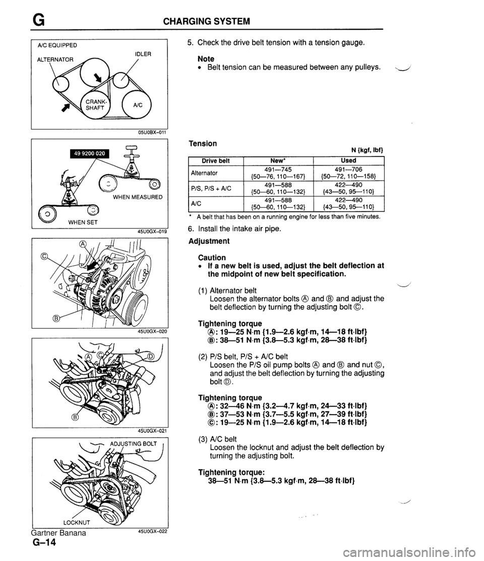
CHARGING SYSTEM I AIC EQUIPPED I WHEN MEASURED 45UOGX-015 - ADJUSTING BOLT I I 5. Check the drive belt tension with a tension gauge. Note Belt tension can be measured between any pulleys. J Tension N {kgf, Ibf) A belt that has been on a ruining engine for less than five minutes. Alternator 'IS
+ A/C 6. Install the intake air pipe. Used Drive belt Adjustment New* I Caution If a new belt is used, adjust the belt deflection at the midpoint of new belt specification. 491-745 (50-76,110-167) 49 1-588 (50-60, 11 0-1 32) d (1) Alternator belt Loosen the alternator bolts @ and @ and adjust the belt deflection by turning the adjusting bolt 0. 491-706 (50-72,110-158) 422490 (43-50,95--110) Tightening torque @: 19-25 N.m (1.9-2.6 kgf.m, 14-1 8 ft4bf) @: 38-51 N.m (3.8-5.3 kgf,m, 28-38 ft-lbf) (2) PIS belt, PIS + AIC belt Loosen the PIS oil pump bolts @ and @ and nut 0, and adjust the belt deflection by turning the adjusting bolt 0. Tightening torque @: 3246 N.m (3.24.7 kgf.m, 24--33 ft4bf) @: 37-53 N.m (3.7-5.5 kgf,m, 27-39 ft-lbf) 0: 19-25 N.m (1.9-2.6 kgf-m, 14-1 8 ft-lbf) (3) AIC belt Loosen the locknut and adjust the belt deflection by turning the adjusting bolt. Tightening torque: 38-51 N.m (3.8-5.3 kgf-m, 28-38 ft-lbf) Gartner Banana
Page 322 of 1708
IGNITION SYSTEM G IGNITION SYSTEM f PREPARATION b SST r I I 49 BO19 9AO For inspection of System ignition timing selector CIRCUIT DIAGRAM CRANKSHAFT POSITION SENSOR SIGNAL w 9 c PCME 3 IGNITION COlL (WITH IGNITER) IGNITION COlL TO (WITH IGNITER) SPARK PLUG I I I 6'5) IGT2 SIGNAL 1 IGNITER - GND 3 1 h - - CRANKSHAFT POSITION SENSOR IGNITION COIL u Note If a timing light is used to check for spark, some lights do not light at Nos.2 and 4 cylinders even if the ignition system is normal. Gartner Banana