1994 JEEP CHEROKEE service
[x] Cancel search: servicePage 201 of 1784
(5) Mark or tag HCU hydraulic lines for assembly
reference.
(6) Disconnect hydraulic lines at HCU.
(7) Move HCU harness and air cleaner hose pipe
aside for access to HCU bracket nuts.
(8) Remove single bolt and two nuts attaching
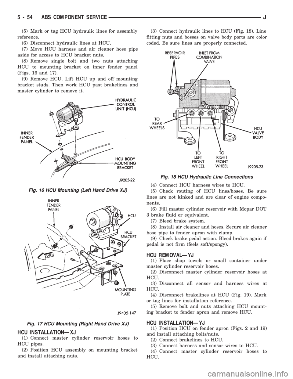
HCU to mounting bracket on inner fender panel
(Figs. 16 and 17).
(9) Remove HCU. Lift HCU up and off mounting
bracket studs. Then work HCU past brakelines and
master cylinder to remove it.
HCU INSTALLATIONÐXJ
(1) Connect master cylinder reservoir hoses to
HCU pipes.
(2) Position HCU assembly on mounting bracket
and install attaching nuts.(3) Connect hydraulic lines to HCU (Fig. 18). Line
fitting nuts and bosses on valve body ports are color
coded. Be sure lines are properly connected.
(4) Connect HCU harness wires to HCU.
(5) Check routing of HCU lines/hoses. Be sure
lines are not kinked and are clear of engine compo-
nents.
(6) Fill master cylinder reservoir with Mopar DOT
3 brake fluid or equivalent.
(7) Bleed brake system.
(8) Install air cleaner and hoses. Secure air cleaner
hose pipe to fender apron with clamp.
(9) Check brake pedal action. Bleed brakes again if
pedal is not firm (feels soft/spongy).
HCU REMOVALÐYJ
(1) Place shop towels or small container under
master cylinder reservoir hoses.
(2) Disconnect master cylinder reservoir hoses at
HCU.
(3) Disconnect all sensor and harness wires at
HCU.
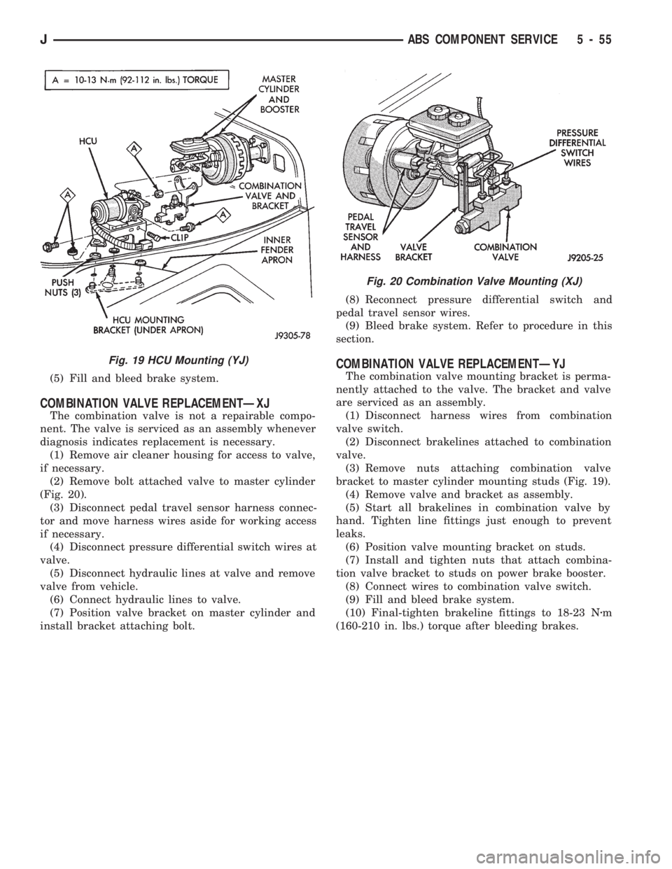
(4) Disconnect brakelines at HCU (Fig. 19). Mark
or tag lines for installation reference.
(5) Remove bolt and nuts attaching HCU mount-
ing bracket to fender apron and remove HCU.
HCU INSTALLATIONÐYJ
(1) Position HCU on fender apron (Figs. 2 and 19)
and install attaching bolts/nuts.
(2) Connect brakelines to HCU.
(3) Connect harness and sensor wires to HCU.
(4) Connect master cylinder reservoir hoses to
HCU.
Fig. 16 HCU Mounting (Left Hand Drive XJ)
Fig. 17 HCU Mounting (Right Hand Drive XJ)
Fig. 18 HCU Hydraulic Line Connections
5 - 54 ABS COMPONENT SERVICEJ
Page 202 of 1784
(5) Fill and bleed brake system.
COMBINATION VALVE REPLACEMENTÐXJ
The combination valve is not a repairable compo-
nent. The valve is serviced as an assembly whenever
diagnosis indicates replacement is necessary.
(1) Remove air cleaner housing for access to valve,
if necessary.
(2) Remove bolt attached valve to master cylinder
(Fig. 20).
(3) Disconnect pedal travel sensor harness connec-
tor and move harness wires aside for working access
if necessary.
(4) Disconnect pressure differential switch wires at
valve.
(5) Disconnect hydraulic lines at valve and remove
valve from vehicle.
(6) Connect hydraulic lines to valve.
(7) Position valve bracket on master cylinder and
install bracket attaching bolt.(8) Reconnect pressure differential switch and
pedal travel sensor wires.
(9) Bleed brake system. Refer to procedure in this
section.
COMBINATION VALVE REPLACEMENTÐYJ
The combination valve mounting bracket is perma-
nently attached to the valve. The bracket and valve
are serviced as an assembly.
(1) Disconnect harness wires from combination
valve switch.
(2) Disconnect brakelines attached to combination
valve.
(3) Remove nuts attaching combination valve
bracket to master cylinder mounting studs (Fig. 19).
(4) Remove valve and bracket as assembly.
(5) Start all brakelines in combination valve by
hand. Tighten line fittings just enough to prevent
leaks.
(6) Position valve mounting bracket on studs.
(7) Install and tighten nuts that attach combina-
tion valve bracket to studs on power brake booster.
(8) Connect wires to combination valve switch.
(9) Fill and bleed brake system.
(10) Final-tighten brakeline fittings to 18-23 Nzm
(160-210 in. lbs.) torque after bleeding brakes.
Fig. 19 HCU Mounting (YJ)
Fig. 20 Combination Valve Mounting (XJ)
JABS COMPONENT SERVICE 5 - 55
Page 203 of 1784
PARKING BRAKES
INDEX
page page
General Service Information................ 56
Parking Brake Adjustment (XJ/YJ)............ 63
Parking Brake Cable Tensioner Replacement (XJ).61
Parking Brake Front Cable Replacement (YJ) . . . 62
Parking Brake Lever Installation
(XJ with Full Console)................... 60
Parking Brake Lever Installation
(XJ with Mini Console)................... 58
Parking Brake Lever Installation
(XJ Without Console).................... 60
Parking Brake Lever Removal
(XJ with Full Console).................... 59
Parking Brake Lever Removal
(XJ with Mini Console)................... 58
Parking Brake Lever Removal (XJ Without Console).60
Parking Brake Operation................... 56
Parking Brake Pedal Installation (YJ).......... 61
Parking Brake Pedal Removal (YJ)........... 61
Parking Brake Rear Cable Replacement (XJ) . . . 62
Parking Brake Rear Cable Replacement (YJ) . . . 63
GENERAL SERVICE INFORMATION
Parking brake adjustment is controlled by a
cable tensioner mechanism. The tensioner mech-
anism is used on 1991 through 1994 YJ models
and XJ models starting with 1992 models. The
cable tensioner, once adjusted at the factory,
will not need further adjustment under normal
circumstances. There are only two instances
when adjustment is required. The first is when a
new tensioner, or cables have been installed.
And the second, is when the tensioner and ca-
bles are disconnected for access to other brake
components.
PARKING BRAKE OPERATION
The rear brakes are utilized for the parking brake
function. They are actuated hydraulically during nor-
mal brake operation but are mechanically actuated
for parking brake operation.
Parking Brake Components
The rear brakeshoes are applied by a system of le-
vers and cables for parking brake operation. A foot
or hand operated lever in the passenger compartment
is the main application device. Actuating levers on
the secondary brakeshoes move the shoes directly
into contact with the drum braking surface. The ac-
tuating levers are interconnected by a system of ca-
bles and a tensioner mechanism. The tensioner
mechanism controls parking brake adjustment.
On XJ models, the cable tensioner is part of the le-
ver assembly. On YJ models, the tensioner and
equalizer are mounted in a bracket attached to the
underbody.
On YJ models, the parking brake front cable is at-
tached to the foot pedal at one end and the cable ten-
sioner at the other. The tensioner is connected to the
equalizer which is the connecting device for the rear
cables (Fig. 1).
On XJ models, the cable tensioner is connected di-rectly to the hand lever (a front cable is not used).
The tensioner rod is attached to the equalizer which
is the connecting point for the rear cables (Fig. 2).
The rear cables are connected to the actuating le-
ver on each secondary brakeshoe. The levers are at-
tached to the brakeshoes by a pin either pressed into,
or welded to the lever. A clip is used to secure the
pin in the brakeshoe. The pin allows each lever to
pivot independently of the brakeshoe.
Struts, installed between each brakeshoe, are used
to maintain shoe alignment and equal motion when
the parking brakes are applied. Each strut is
equipped with a combination tension and anti-rattle
spring.
Parking Brake Application
To apply the parking brakes, the foot pedal is
pressed downward, or the hand lever is pulled up-
ward, to an engaged position. This pulls the rear
brakeshoe actuating levers forward, by means of the
interconnected tensioner and cables.
As the actuating lever is pulled forward, the park-
ing brake strut (which is connected to both shoes),
exerts a linear force against the primary brakeshoe.
This action presses the primary shoe into contact
with the drum.
Once the primary shoe contacts the brake drum,
force exerted through the strut does not end. Instead,
further lever movement continues to exert force
against the strut; only this time, in a reverse direc-
tion. The strut force then causes the secondary shoe
to pivot into contact with the drum as well.
The brakeshoes will remain engaged with the
drum until the levers and cables are released. A gear
type ratcheting mechanism is used to hold the pedal
or lever in an applied position. Parking brake release
is accomplished by means of the release handle on
YJ models. Or by the hand lever release button on
XJ models.
5 - 56 PARKING BRAKESJ
Page 209 of 1784
(2) Position pedal assembly on panel and install
mounting stud nuts and pedal-to-dash bolt.
(3) Install ground wire on upper end of pedal-to-
dash bolt and secure wire with attaching nut.
(4) Connect warning light switch wire to pedal
connector.
(5) Install dash-to-instrument panel brace rod, if
equipped.
(6) Raise vehicle and adjust brake cables. Refer to
procedure in Service Adjustment section.
PARKING BRAKE REAR CABLE REPLACEMENT (XJ)
(1) Raise vehicle and loosen equalizer nuts until
rear cables are slack.
(2) Disengage cable from equalizer and remove ca-
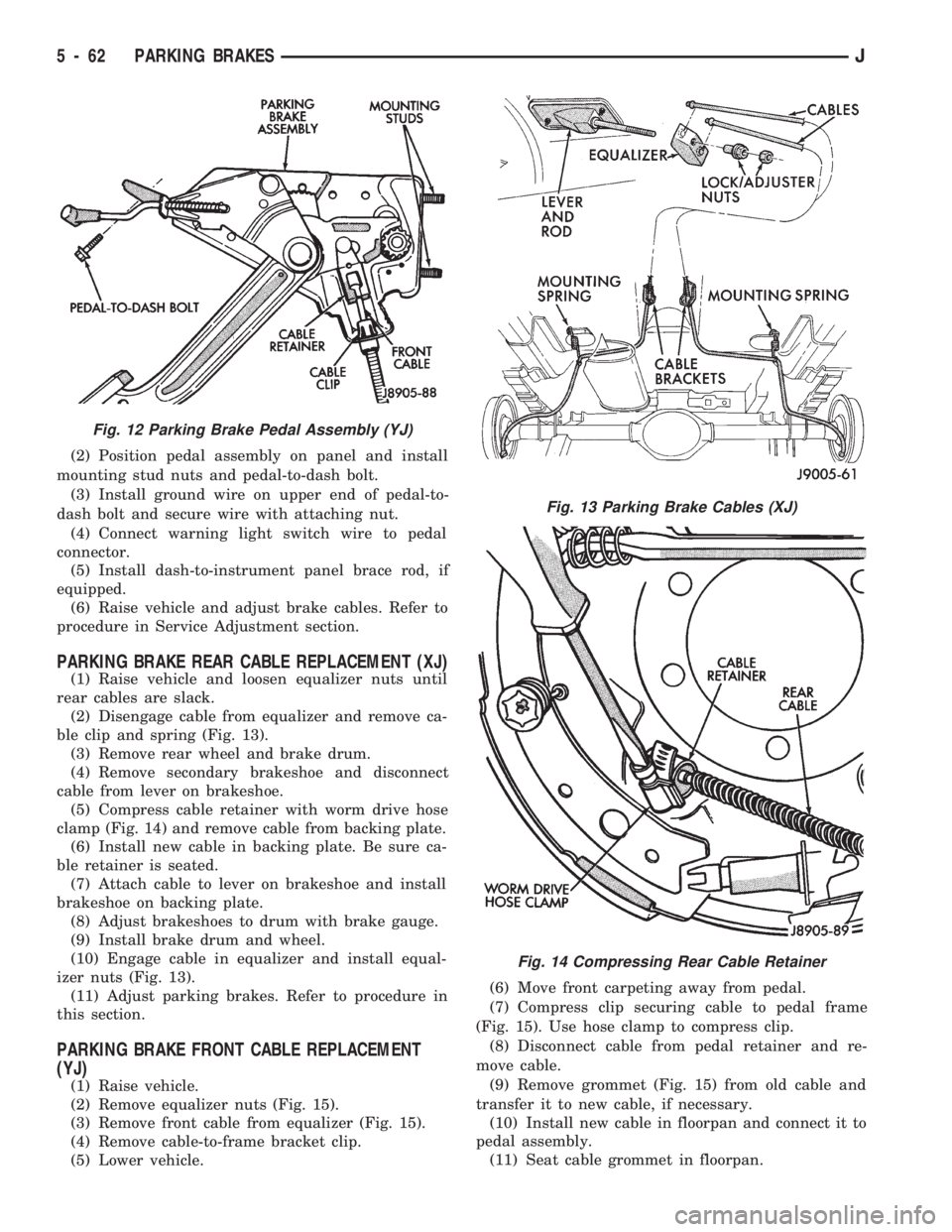
ble clip and spring (Fig. 13).
(3) Remove rear wheel and brake drum.
(4) Remove secondary brakeshoe and disconnect
cable from lever on brakeshoe.
(5) Compress cable retainer with worm drive hose
clamp (Fig. 14) and remove cable from backing plate.
(6) Install new cable in backing plate. Be sure ca-
ble retainer is seated.
(7) Attach cable to lever on brakeshoe and install
brakeshoe on backing plate.
(8) Adjust brakeshoes to drum with brake gauge.
(9) Install brake drum and wheel.
(10) Engage cable in equalizer and install equal-
izer nuts (Fig. 13).
(11) Adjust parking brakes. Refer to procedure in
this section.
PARKING BRAKE FRONT CABLE REPLACEMENT
(YJ)
(1) Raise vehicle.
(2) Remove equalizer nuts (Fig. 15).
(3) Remove front cable from equalizer (Fig. 15).
(4) Remove cable-to-frame bracket clip.
(5) Lower vehicle.(6) Move front carpeting away from pedal.
(7) Compress clip securing cable to pedal frame
(Fig. 15). Use hose clamp to compress clip.
(8) Disconnect cable from pedal retainer and re-
move cable.
(9) Remove grommet (Fig. 15) from old cable and
transfer it to new cable, if necessary.
(10) Install new cable in floorpan and connect it to
pedal assembly.
(11) Seat cable grommet in floorpan.
Fig. 12 Parking Brake Pedal Assembly (YJ)
Fig. 13 Parking Brake Cables (XJ)
Fig. 14 Compressing Rear Cable Retainer
5 - 62 PARKING BRAKESJ
Page 210 of 1784
(12) Raise the vehicle.
(13) Install cable-to-frame retaining clip.
(14) Insert cable in equalizer and install equalizer
washer and nuts.
(15) Adjust parking brakes as described in Service
Adjustment section.
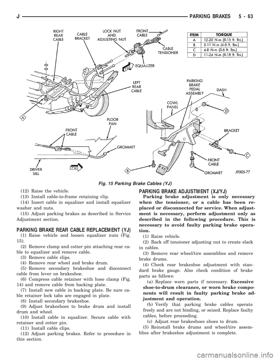
PARKING BRAKE REAR CABLE REPLACEMENT (YJ)
(1) Raise vehicle and loosen equalizer nuts (Fig.
15).
(2) Remove clamp and cotter pin attaching rear ca-
ble to equalizer and remove cable.
(3) Remove cable clips.
(4) Remove rear wheel and brake drum.
(5) Remove secondary brakeshoe and disconnect
cable from lever on brakeshoe.
(6) Compress cable retainer with hose clamp (Fig.
14) and remove cable from backing plate.
(7) Install new cable in backing plate. Be sure ca-
ble retainer lock tabs are engaged in plate.
(8) Install secondary brakeshoe.
(9) Adjust brakeshoes to brake drum and install
drum and wheel.
(10) Install cable in equalizer. Secure cable with
retainer and cotter pin.
(11) Install cable clips.
(12) Adjust parking brakes. Refer to procedure in
this section.
PARKING BRAKE ADJUSTMENT (XJ/YJ)
Parking brake adjustment is only necessary
when the tensioner, or a cable has been re-
placed or disconnected for service. When adjust-
ment is necessary, perform adjustment only as
described in the following procedure. This is
necessary to avoid faulty parking brake opera-
tion.
(1) Raise vehicle.
(2) Back off tensioner adjusting nut to create slack
in cables.
(3) Remove rear wheel/tire assemblies and remove
brake drums.
(4) Check rear brakeshoe adjustment with stan-
dard brake gauge. Also check condition of brake
parts as follows:
(a) Replace worn parts if necessary.Excessive
shoe-to-drum clearance, or worn brake compo-
nents will result in faulty parking brake ad-
justment and operation.
(b) Verify that parking brake cables operate
freely and are not binding, or seized. Replace faulty
cables, before proceeding.
(c) Adjust rear brakeshoes shoes to drum.
(5) Reinstall brake drums and wheel/tire assem-
blies after brakeshoe adjustment is complete.
Fig. 15 Parking Brake Cables (YJ)
JPARKING BRAKES 5 - 63
Page 212 of 1784
BRAKE PEDAL AND BRAKELIGHT SWITCH
INDEX
page page
Brake Pedal Installation.................... 66
Brake Pedal Removal..................... 65
Brake Pedal Service...................... 65
Brakelight Switch Adjustment................ 66Brakelight Switch Installation................ 66
Brakelight Switch Removal................. 66
General Information....................... 65
GENERAL INFORMATION
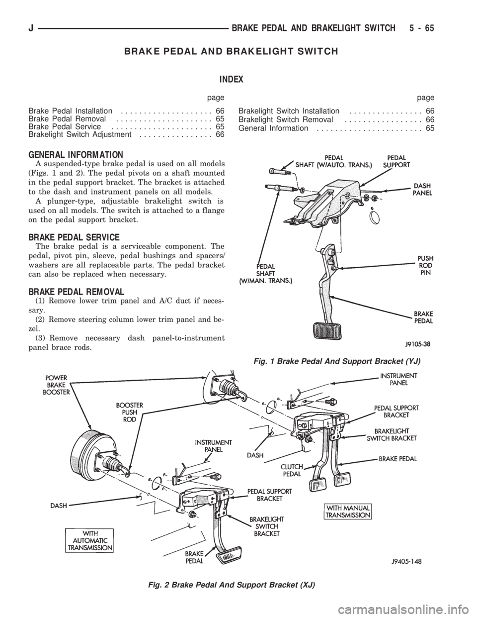
A suspended-type brake pedal is used on all models
(Figs. 1 and 2). The pedal pivots on a shaft mounted
in the pedal support bracket. The bracket is attached
to the dash and instrument panels on all models.
A plunger-type, adjustable brakelight switch is
used on all models. The switch is attached to a flange
on the pedal support bracket.
BRAKE PEDAL SERVICE
The brake pedal is a serviceable component. The
pedal, pivot pin, sleeve, pedal bushings and spacers/
washers are all replaceable parts. The pedal bracket
can also be replaced when necessary.
BRAKE PEDAL REMOVAL
(1) Remove lower trim panel and A/C duct if neces-
sary.
(2) Remove steering column lower trim panel and be-
zel.
(3) Remove necessary dash panel-to-instrument
panel brace rods.
Fig. 1 Brake Pedal And Support Bracket (YJ)
Fig. 2 Brake Pedal And Support Bracket (XJ)
JBRAKE PEDAL AND BRAKELIGHT SWITCH 5 - 65
Page 216 of 1784
CLUTCH
CONTENTS
page page
CLUTCH DIAGNOSIS..................... 3
CLUTCH SERVICE...................... 10GENERAL INFORMATION.................. 1
GENERAL INFORMATION
INDEX
page page
Clutch Component Lubrication................ 1
Clutch Components........................ 1Clutch Linkage Fluid....................... 1
Clutch Operation.......................... 2
CLUTCH COMPONENTS
MECHANICAL COMPONENTS
The clutch mechanism in XJ/YJ models with man-
ual transmission consists of a single, dry-type clutch
disc and a diaphragm style clutch cover. A hydraulic
linkage is used to operate the clutch disc and cover.
The transmission input shaft is supported in the
crankshaft by a bearing. A sleeve type release bear-
ing is used to engage and disengage the clutch cover
pressure plate.
The release bearing is operated by a release fork in
the clutch housing. The fork pivots on a ball stud
mounted inside the housing. The release fork is actu-
ated by a hydraulic slave cylinder mounted in the
housing. The slave cylinder is operated by a clutch
master cylinder mounted on the dash panel. The cyl-
inder push rod is connected to the clutch pedal.
The clutch disc has cushion springs in the disc hub.
The clutch disc facing is riveted to the hub. The fac-
ing is made from a non-asbestos material. The clutch
cover pressure plate is a diaphragm type with a one-
piece spring and multiple release fingers. The pres-
sure plate release fingers are preset during
manufacture and are not adjustable.
HYDRAULIC LINKAGE COMPONENTS
The hydraulic linkage consists of a clutch master
cylinder with integral reservoir, a clutch slave cylin-
der and an interconnecting fluid line.
The clutch master cylinder push rod is connected to
the clutch pedal. The slave cylinder push rod is con-
nected to the clutch release fork. The master cylinder
is mounted on the driver side of the dash panel ad-jacent to the brake master cylinder and booster as-
sembly. This positioning is similar for both left and
right hand drive models.
CLUTCH LINKAGE FLUID
The integral clutch master cylinder reservoir, slave
cylinder and fluid lines are prefilled with fluid prior
to assembly operations.
The hydraulic system should not require additional
fluid under normal circumstances. In fact,the reser-
voir fluid level will actually increase as normal
clutch wear occurs. For this reason, it is impor-
tant to avoid overfilling, or removing fluid from
the reservoir.
If inspection or diagnosis indicates additional fluid
may be needed, use Mopar brake fluid, or an equiv-
alent meeting standards SAE J1703 and DOT 3. Do
not use any other type of fluid.
CLUTCH COMPONENT LUBRICATION
Proper clutch component lubrication is important
to satisfactory operation. Using the correct lubricant
and not overlubricating are equally important. Apply
recommended lubricant sparingly to avoid disc and
pressure plate contamination.
Clutch and transmission components requiring lu-
brication are:
²pilot bearing
²release lever pivot ball stud
²release lever contact surfaces
²release bearing bore
²clutch disc hub splines
²clutch pedal pivot shaft bore
²clutch pedal bushings
²input shaft splines
JCLUTCH 6 - 1
Page 219 of 1784
when handling the cover and disc. Impact can distort
the cover, diaphragm spring, release fingers and the
hub of the clutch disc.
Use an alignment tool when positioning the disc on
the flywheel. The tool prevents accidental misalign-
ment which could result in cover distortion and disc
damage.
A frequent cause of clutch cover distortion (and
consequent misalignment) is improper bolt tighten-
ing. To avoid warping the cover, the bolts must tight-
ened alternately (diagonal pattern) and evenly (2-3
threads at a time) to specified torque.
Clutch Housing Misalignment
Clutch housing alignment is important to proper
clutch operation. The housing maintains alignment
between the crankshaft and transmission input shaft.
Misalignment can cause clutch noise, hard shifting,
incomplete release and chatter. It can also result in
premature wear of the pilot bearing, cover release
fingers and clutch disc. In severe cases, misalign-
ment can also cause premature wear of the transmis-
sion input shaft and shaft bearing.
Housing misalignment is generally caused by in-
correct seating on the engine or transmission, loose
housing bolts, missing alignment dowels or housing
damage. Infrequently, misalignment may also be
caused by housing mounting surfaces that are not
completely parallel. Misalignment can be corrected
with shims.INSTALLATION METHODS AND PARTS
USAGE
Distortion of clutch components during installation
and the use of non-standard components are addi-
tional causes of clutch malfunction.
Improper clutch cover bolt tightening can distort
the cover. The usual result is clutch grab, chatter
and rapid wear. Tighten the cover bolts as described
in Clutch Service section.
An improperly seated flywheel and/or clutch hous-
ing are additional causes of clutch failure. Improper
seating will produce misalignment and additional
clutch problems.
The use of non-standard or low quality parts will
also lead to problems and wear. Use recommended
factory quality parts to avoid comebacks.
INSPECTION AND DIAGNOSIS CHARTS
The clutch inspection chart (Fig. 1) outlines items
to be checked before and during clutch installation.
Use the chart as a check list to help avoid overlook-
ing potential problem sources during service opera-
tions.
The diagnosis charts describe common clutch prob-
lems, causes and correction. Fault conditions are
listed at the top of each chart. Conditions, causes and
corrective action are outlined in the indicated col-
umns.
The charts are provided as a convenient reference
when diagnosing faulty clutch operation.
6 - 4 CLUTCH DIAGNOSISJ