1994 JEEP CHEROKEE diagram
[x] Cancel search: diagramPage 1006 of 1784
EXTENDED IDLE SWITCH TEST
OPTIONAL POLICE PACKAGE ONLY
OPERATION
The extended idle switch is used to raise the en-
gine idle speed to approximately 1000 rpm when the
shifter is in either the Park or Neutral position. A
rocker-type 2-wire switch (extended idle switch) is
mounted to the instrument panel.This switch is
available only with 4.0L engine when supplied
with the optional police package.
TESTING
The extended idle switch will control a ground cir-
cuit going to the powertrain control module (PCM).
When a ground signal (through this switch) has been
received at pin number 10 in the PCM, engine idle
speed will increase.
Bring the engine to normal operating temperature
and turn the extended idle switch to the ON position.
Engine speed should now increase to approximately
1000 rpm when the shifter is in either the Park or
Neutral position. If engine speed does not increase,
apply a good ground to pin number 10 at the PCM
using a small paper clip. Be careful not to damage
the wiring with the paper clip. If the engine speed
now increases, it can be assumed that the PCM is
functioning correctly. Check the instrument panel
mounted switch for a closed ground circuit when in
the ON position. If the engine speed will not increase
after applying a ground to pin number 10, replace
the PCM. Refer to Group 8W, Wiring Diagrams for
circuit and wiring information.
THROTTLE POSITION SENSOR (TPS) TEST
To perform a complete test of the sensor and its cir-
cuitry, refer to DRB scan tool and appropriate Pow-
ertrain Diagnostics Procedures manual. To test the
sensor only, refer to the following:
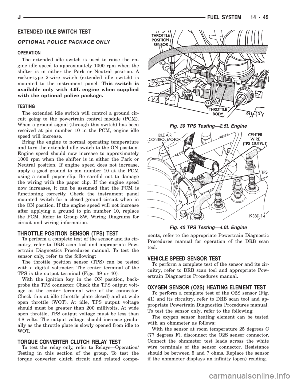
The throttle position sensor (TPS) can be tested
with a digital voltmeter. The center terminal of the
TPS is the output terminal (Figs. 39 or 40).
With the ignition key in the ON position, back-
probe the TPS connector. Check the TPS output volt-
age at the center terminal wire of the connector.
Check this at idle (throttle plate closed) and at wide
open throttle (WOT). At idle, TPS output voltage
should must be greater than 200 millivolts. At wide
open throttle, TPS output voltage must be less than
4.8 volts. The output voltage should increase gradu-
ally as the throttle plate is slowly opened from idle to
WOT.
TORQUE CONVERTER CLUTCH RELAY TEST
To test the relay only, refer to RelaysÐOperation/
Testing in this section of the group. To test the
torque converter clutch circuit and related compo-nents, refer to the appropriate Powertrain Diagnostic
Procedures manual for operation of the DRB scan
tool.
VEHICLE SPEED SENSOR TEST
To perform a complete test of the sensor and its cir-
cuitry, refer to DRB scan tool and appropriate Pow-
ertrain Diagnostics Procedures manual.
OXYGEN SENSOR (O2S) HEATING ELEMENT TEST
To perform a complete test of the O2S sensor (Fig.
41) and its circuitry, refer to DRB scan tool and ap-
propriate Powertrain Diagnostics Procedures manual.
To test the sensor only, refer to the following:
The oxygen sensor heating element can be tested
with an ohmmeter as follows:
With the sensor at room temperature 25 degrees C
(77 degrees F), disconnect the O2S sensor connector.
Connect the ohmmeter test leads across the white
wire terminals of the sensor connector. Resistance
should be between 5 and 7 ohms. Replace the sensor
if the ohmmeter displays an infinity (open) reading.
Fig. 39 TPS TestingÐ2.5L Engine
Fig. 40 TPS TestingÐ4.0L Engine
JFUEL SYSTEM 14 - 45
Page 1009 of 1784
87 and 30. Continuity should not be present between
terminals number 87A and 30.
(8) Disconnect jumper wires from relay and 12
Volt power source.
If continuity or resistance tests did not pass, re-
place relay. If tests passed, refer to Group 8W, Wir-
ing Diagrams for additional circuit information. Also
refer to the appropriate Powertrain Diagnostic Proce-
dures manual for operation of the DRB scan tool.
STARTER MOTOR RELAY TEST
Refer to Group 8A, Battery/Starting/Charging/Sys-
tem Diagnostics, for starter motor relay testing.
INJECTOR TEST
Disconnect the injector wire connector from the in-
jector. Place an ohmmeter on the injector terminals.
Resistance reading should be approximately 14.5
ohms61.2 ohms at 20ÉC (68ÉF). Proceed to following
Injector Diagnosis chart.
FUEL SYSTEM PRESSURE TEST
Refer to the Fuel Delivery System section of this
group. See Fuel System Pressure Test.
ON-BOARD DIAGNOSTICS (OBD)
The Powertrain Control Module (PCM) has been
programmed to monitor many different circuits of the
fuel injection system. If a problem is sensed in a
monitored circuit often enough to indicate an actual
problem, a Diagnostic Trouble Code (DTC) is stored.
The DTC will be stored in the PCM memory for
eventual display to the service technician. If the
problem is repaired or ceases to exist, the PCM can-
cels the DTC after 51 engine starts.
Certain criteria must be met for a diagnostic trou-
ble code (DTC) to be entered into PCM memory. The
criteria may be a specific range of engine rpm, en-
gine temperature and/or input voltage to the PCM.
It is possible that a DTC for a monitored circuit
may not be entered into memory even though a mal-
function has occurred. This may happen because one
of the DTC criteria for the circuit has not been met.
Example: assume that one of the criteria for the
MAP sensor circuit is that the engine must be oper-
ating between 750 and 2000 rpm to be monitored for
a DTC. If the MAP sensor output circuit shorts to
ground when the engine rpm is above 2400 rpm, a 0
volt input will be seen by the PCM. A DTC will not
be entered into memory because the condition does
not occur within the specified rpm range.
A DTC indicates that the powertrain control mod-
ule (PCM) has recognized an abnormal signal in a
circuit or the system. A DTC may indicate the result
of a failure, but never identify the failed component
directly.There are several operating conditions that the
PCM does not monitor and set a DTC for. Refer to
the following Monitored Circuits and Non-Monitored
Circuits in this section.
MONITORED CIRCUITS
The powertrain control module (PCM) can detect
certain problems in the fuel injection system.
Open or Shorted Circuit- The PCM can deter-
mine if sensor output (which is the input to PCM) is
within proper range. It also determines if the circuit
is open or shorted.
Output Device Current Flow- The PCM senses
whether the output devices are hooked up.
If there is a problem with the circuit, the PCM
senses whether the circuit is open, shorted to ground
(-), or shorted to (+) voltage.
Oxygen Sensor- The PCM can determine if the
oxygen sensor is switching between rich and lean.
This is, once the system has entered Closed Loop. Re-
fer to Open Loop/Closed Loop Modes Of Operation in
the Component Description/System Operation section
for an explanation of Closed (or Open) Loop opera-
tion.
NON-MONITORED CIRCUITS
The PCM does not monitor the following circuits,
systems or conditions that could have malfunctions
that result in driveability problems. A Diagnostic
Trouble Code (DTC) may not be displayed for these
conditions.
Fuel Pressure: Fuel pressure is controlled by the
vacuum assisted fuel pressure regulator. The PCM
cannot detect a clogged fuel pump inlet filter, clogged
in-line fuel filter, or a pinched fuel supply or return
line. However, these could result in a rich or lean
condition causing an oxygen sensor DTC to be stored
in the PCM.
Secondary Ignition Circuit: The PCM cannot
detect an inoperative ignition coil, fouled or worn
spark plugs, ignition cross firing, or open circuited
spark plug cables.
Engine Timing: The PCM cannot detect an incor-
rectly indexed timing chain, camshaft sprocket or
crankshaft sprocket. The PCM also cannot detect an
incorrectly indexed distributor. However, these could
result in a rich or lean condition causing an oxygen
sensor DTC to be stored in the PCM.
Cylinder Compression: The PCM cannot detect
uneven, low, or high engine cylinder compression.
Exhaust System: The PCM cannot detect a
plugged, restricted or leaking exhaust system.
Fuel Injector Malfunctions: The PCM cannot de-
termine if the fuel injector is clogged, or the wrong
injector is installed. However, these could result in a
rich or lean condition causing an oxygen sensor DTC
to be stored in the PCM.
14 - 48 FUEL SYSTEMJ
Page 1167 of 1784
SHIFT RAIL AND FORK INSTALLATION
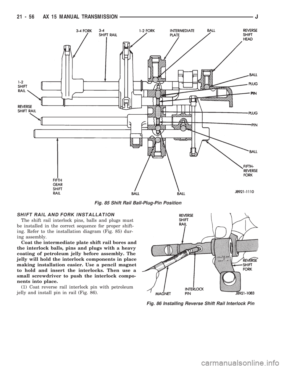
The shift rail interlock pins, balls and plugs must
be installed in the correct sequence for proper shift-
ing. Refer to the installation diagram (Fig. 85) dur-
ing assembly.
Coat the intermediate plate shift rail bores and
the interlock balls, pins and plugs with a heavy
coating of petroleum jelly before assembly. The
jelly will hold the interlock components in place
making installation easier. Use a pencil magnet
to hold and insert the interlocks. Then use a
small screwdriver to push the interlock compo-
nents into place.
(1) Coat reverse rail interlock pin with petroleum
jelly and install pin in rail (Fig. 86).
Fig. 85 Shift Rail Ball-Plug-Pin Position
Fig. 86 Installing Reverse Shift Rail Interlock Pin
21 - 56 AX 15 MANUAL TRANSMISSIONJ
Page 1677 of 1784
SERVICE DIAGNOSISÐELECTRICAL
BLOWER CONTROLSÐXJ VEHICLES
DESCRIPTION
The blower motor delivers air to the inside of the
vehicle. Its speed is controlled by the blower switch
and the blower resistors. With the switch in LO, part
of the battery voltage is supplied to the motor
through all of the resistors. The motor runs slowly.
As the blower switch is moved to a higher speed, the
switch allows more voltage to be applied to the
blower motor, which will increase its speed. When
the switch is in HI, the blower resistors are bypassed
and battery voltage is applied directly to the blower
motor. The motor runs at the fastest speed in this
mode.
DIAGNOSIS
Refer to the Group 8W, Wiring Diagrams for com-
plete system schematic.
1. BLOWER MOTOR INOPERATIVE
²Remove and inspect fuse. If the fuse is blown, re-
place fuse.
2. BLOWER MOTOR INOPERATIVE (HI Posi-
tion)
Put the ignition switch in RUN, the select switch
in HEAT and the blower switch on HI.
²Blower motor connector (Terminal A) should be
battery voltage. If not go to next step.
²Blower motor connector (Terminal B) should be 0
ohms. If not, repair wire to ground.
²Blower switch connector (Terminal C) should be
battery voltage. If battery voltage replace blower
switch. If not, replace select switch.
3. BLOWER MOTOR INOPERATIVE (LO, M1
& M2 Positions)
Ignition switch in RUN, select switch in HEAT.
²Blower resistors connector (Terminal D) should be
battery voltage. If not, replace select switch.
²Blower resistors connector (Terminal C) should be
battery voltage. If not, replace blower switch.
²Blower resistors connector (Terminal A) should be
battery voltage. If not, replace blower switch.
²Blower resistors connector (Terminal B) should be
battery voltage. If not, replace blower resistor.
AIR CONDITIONING SYSTEMÐXJ VEHICLES
DESCRIPTION
The A/C Compressor Clutch is belt-driven by the
engine. A clutch, operated by a solenoid, automati-
cally turns the compressor on and off to control evap-
orator icing.
The A/C Compressor Clutch operation is controlled
by several components: the A/C Low-Pressure
Switch, Thermostat Switch, Fuel Pump Relay, A/C
Clutch Relay and the Engine Controller.The A/C low pressure switch opens when there is
not enough refrigerant in the system. When this hap-
pens, voltage is no longer present at the Engine Con-
troller. The Engine Controller will turn off the A/C
clutch relay. With the proper refrigerant level in the
system, the low pressure switch remains closed.
When the evaporator temperature is low enough to
ice the cooling coils, the thermostat switch opens.
The Engine Controller will turn off the A/C clutch.
The thermostat switch closes when the temperature
rises. The Engine Controller will then turn the A/C
clutch relay on again.
DIAGNOSIS
Refer to the Group 8W, Wiring Diagrams for com-
plete system schematic.
With engine running, Engine Controller may delay
A/C clutch up to 30 seconds.
1. A/C COMPRESSOR CLUTCH INOPERA-
TIVE
Clutch connector disconnected.
²Jumper fused test lead, battery to clutch connec-
tor, clutch should operate. If not, replace compressor
clutch assembly.
2. A/C LOW PRESSURE SWITCH
Ignition in RUN, A/C controls in MAX or NORM.
²Low pressure switch connector (Terminal A)
should be battery voltage. If not, repair open to select
switch.
²Low pressure switch connector (Terminal C)
should be battery voltage. If not, check switch resis-
tance and check freon pressure.
3. A/C CLUTCH RELAY
Engine RUNNING, A/C controls in MAX or
NORM.
²Relay connector Pin 4 to ground should be battery
voltage. If not, check fuse F6 in Power Distribution
Center.
²Ground A/C clutch relay (Terminal 5) should have
A/C compressor clutch engagement. If not, check En-
gine Controller Terminals 27, 28 and 34.
HEATING SYSTEMÐYJ VEHICLES
DESCRIPTION
The blower motor circuit begins at a 25 amp fuse
that receives its battery feed from the ignition
switch. From the fuse the circuit extends to a micro-
switch mounted on the heater control.
The micro-switch is normally closed is operated by
a cam on the heater control lever. In all heater con-
trol lever positions, except OFF and VENT, the
blower motor electrical circuit is complete. In the
OFF and VENT positions the cam depresses the mi-
cro-switch lever opening the electrical circuit to the
blower motor.
24 - 14 HEATING AND AIR CONDITIONINGJ
Page 1678 of 1784
The blower switch allows the driver to select 1 of 3
blower speedsÐlow, medium and high. In the high
speed position, the switch connects the motor directly
to the battery source. The remaining 2 slower speeds
are accomplished by routing the battery source
through a resistor assembly.
The resistor and switch are wired in such a way
that only a single wire is needed to operate the
blower motor at 3 different speeds.
DIAGNOSIS
Refer to Group 8W, Wiring Diagrams for complete
system schematic.
1. HEAT/OFF MICRO-SWITCH
Place selector lever in heat mode and turn ignition
switch to RUN.
²Heat/Off micro-switch connector supply side should
be battery voltage. If not, repair open from fuse
No.12.
²Heat/Off micro-switch connector output side should
be battery voltage. If not, replace Heat/Off micro-
switch.
2. BLOWER SWITCH
Turn ignition switch to RUN and place selector le-
ver in HEAT mode.
²Blower switch (terminal A) should be battery volt-
age. If not, repair open from HEAT/OFF switch con-
nector output side to blower switch.
²Blower switch (terminal D) with blower switch in
HI should be battery voltage. If not, replace blower
switch.
²Blower switch (terminal C) with blower switch in
LO should be battery voltage. If not, replace blower
switch.
²Blower switch (terminal B) with blower switch in
MED should be battery voltage. If not replace blower
switch.
3. BLOWER RESISTOR
Turn ignition switch to RUN for voltage tests and
turn ignition switch to OFF for resistance tests.
²Blower resistor (Terminal A) with blower switch in
LO should be battery voltage. If not, repair open be-
tween blower switch and blower resistor.
²Blower resistor (Terminal C) with blower switch in
MED should be battery voltage. If not, repair open
between blower switch and blower resistor.
²Blower resistor (Terminal B) with blower switch in
HI should be battery voltage. If not, repair open be-
tween blower switch and blower resistor.
²Blower resistor between Terminals A and B should
be 3.25 ohms, if not replace blower resistor.
²Blower resistor between Terminals B and C should
be 0.60 ohms. If not, replace blower resistor.
²Blower resistor between terminals A and C should
be 2.65 ohms, if not replace blower resistor.4. BLOWER MOTOR
Turn blower motor switch to HI and place selector
lever in HEAT mode. Turn ignition switch to RUN
for voltage tests or to OFF for resistance tests.
²Blower motor voltage should be battery voltage. If
not, repair open from blower switch.
²Blower motor case to clean chassis ground should
be 0 ohms. If not, repair/replace blower motor.
AIR CONDITIONING SYSTEMÐYJ VEHICLES
DESCRIPTION
The air conditioning circuit consists of 3 segments;
battery supply, blower motor and compressor clutch.
The 3 segments have a common connection point at
the blower switch.
The power supply segment of the circuit extends
from the 25 amp HTR/FAN fuse to the blower
switch. From the blower switch, battery feed is
routed to the blower motor and compressor clutch
segments of the circuit.
The blower motor segment consists of the 3 wires
from the blower switch to the motor, the motor itself
and the motor ground wire. Through the switch, the
3 wires connect the motor brushes to battery supply.
When connected to battery feed, the separate brushes
provide the 3 blower speedsÐLO, MED, and HIGH.
In all blower switch positions except OFF, the com-
pressor clutch segment of the circuit also receives
battery feed. ON and OFF cycling of the compressor
and therefore the temperature of the outlet air is
regulated by the thermostatic control. A thermal sen-
sor extends from the control to the evaporator hous-
ing. When the temperature of the evaporator drops
below the set temperature, the thermostatic control
opens the clutch circuit. The circuit remains open un-
til evaporator temperature rises above the set tem-
perature.
The compressor clutch segment of the circuit also
contains a low pressure switch. If the pressure in the
refrigerant system drops due to a leak, the circuit is
opened to prevent damage to the compressor.
The last component in the compressor clutch seg-
ment of the circuit is the clutch coil. When the coil is
connected to battery feed, its windings form an elec-
tromagnet that pulls the clutch hub against the
clutch pulley.
DIAGNOSIS
BLOWER MOTOR
Refer to Group 8W, Wiring Diagrams for complete
system schematic.
1. FUSEÐIgnition in RUN.
²Heater blower motor operates. If not, check fuse
No.12.
JHEATING AND AIR CONDITIONING 24 - 15
Page 1679 of 1784
²Battery side of fuse No.12 should be battery volt-
age. If not, repair open from ignition switch.
²A/C blower switch (terminal A) should be battery
voltage. If not, repair open from fuse No.12.
2. BLOWER SWITCHÐIgnition in RUN.
²A/C blower switch (Terminal A) with blower
switch in any position should be battery voltage. If
not, repair open from fuse panel.
²A/C blower switch (Terminal L) with blower
switch in LO should be battery voltage. If not, re-
place switch.
²A/C blower switch (Terminal M) with blower
switch in MED should be battery voltage. If not, re-
place switch.
²A/C blower switch (Terminal H) with blower
switch in HI should be battery voltage. If not, replace
switch.
3. BLOWER MOTOR
Turn ignition switch to RUN for voltage tests and
turn ignition switch to OFF for resistance tests.
²A/C blower housing to ground (Terminal G) should
be 0 ohms. If not, repair ground connection. If the
blower motor is still inoperative, replace motor.
²A/C blower motor connector (Terminal C) with
blower switch in LO should be battery voltage. If not,
repair open from blower switch. If the blower motor
is still inoperative, replace motor.
²A/C blower motor connector (Terminal B) with
blower switch in MED should be battery voltage. If
not, repair open from blower switch. If the blower
motor is still inoperative, replace motor.
²A/C blower motor connector (Terminal A) with
blower switch in HI should be battery voltage. If not,
repair open from blower switch. If the blower motor
is still inoperative, replace motor.COMPRESSOR CLUTCH
Refer to Group 8W, Wiring Diagrams for complete
system schematic.
With engine running, Engine Controller may delay
A/C clutch up to 30 seconds.
1. COMPRESSOR CLUTCH.
²Jumper wire from battery positive post to A/C
compressor clutch connector (Terminal A), clutch
should engage. If not, go to next step with jumper in-
stalled.
²Jumper wire from clutch coil frame to chassis
ground, clutch should engage. If not, repair clutch
coil ground or replace coil.
2. LOW PRESSURE SWITCH
Turn ignition switch to RUN, A/C blower switch to
ON and thermostatic control set to MAX cool.
²A/C low pressure switch connector (Terminal A)
should be battery voltage. If not, proceed to thermo-
static control tests (Step 3).
²Jumper wire across A/C low pressure switch con-
nector (Terminals A and B), clutch should engage. If
not, check system refrigerant charge. If system is
properly charged, replace A/C low pressure switch.
3. THERMOSTATIC CONTROL
Turn ignition switch to RUN, A/C blower switch to
ON and thermostatic control set to MAX cool.
²Thermostatic control connector (Terminal A)
should be battery voltage. If not, repair open from
blower switch.
²Thermostatic control connector (Terminal B)
should be battery voltage. If not, replace thermo-
static control.
²A/C low pressure switch connector (Terminal A)
should be battery voltage. If not, repair open from
thermostatic control.
24 - 16 HEATING AND AIR CONDITIONINGJ
Page 1686 of 1784
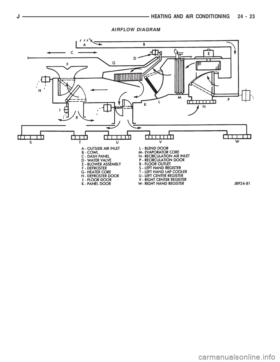
AIRFLOW DIAGRAM
JHEATING AND AIR CONDITIONING 24 - 23
Page 1745 of 1784
30RH/32RH AUTOMATIC TRANSMISSION . . . 21-66
30RH/32RH GENERAL SPECIFICATIONS . . . 21-322
30RH/32RH IN-VEHICLE SERVICE.........21-96
30RH/32RH PRESSURE TEST
SPECIFICATIONS....................21-323
30RH/32RH SNAP RING/THRUST
WASHER/THRUST PLATE
SPECIFICATIONS....................21-322
30RH/32RH TORQUE SPECIFICATIONS....21-323
30RH/32RH TRANSMISSION DIAGNOSIS . . . 21-69,
21-77,21-78,21-79,21-80,21-81,21-82,21-83,21-84,
21-85
30RH/32RH TRANSMISSION OVERHAUL . . . 21-112
30RH/32RH TRANSMISSION REMOVAL
AND INSTALLATION..................21-108
3-2 DOWNSHIFT, HYDRAULIC FLOW
DURING FULL THROTTLE..............21-92
3-2 DOWNSHIFT, HYDRAULIC FLOW
DURING PART THROTTLE..............21-91
4WD INDICATOR......................8E-22
4WD INDICATOR INOPERATIVE............8E-4
4WD INDICATOR LAMP..................8E-2
60-WAY CONNECTOR, POWERTRAIN
CONTROL MODULE (PCM).............14-38
ABBREVIATIONS, SYMBOLS, FUSES........8W-6
ABS BRAKE DIAGNOSIS...................5-3
ABS BRAKES, BRAKE BLEEDINGÐWITH.....5-14
ABS COMPONENT SERVICE...............5-47
ABS FAULT DIAGNOSIS................5-4,5-6
ABS OPERATION IN ANTILOCK BRAKING
MODE..............................5-43
ABS OPERATION IN NORMAL BRAKING
MODE..............................5-43
ABS SYSTEM OPERATION................5-39
ABS SYSTEM WIRING AND ELECTRICAL
CIRCUITS............................5-4
ABS WARNING LIGHT DISPLAY.............5-3
ABSOLUTE PRESSURE (MAP) SENSOR,
MANIFOLD; FUEL SYSTEM.............14-57
ABSOLUTE PRESSURE (MAP) SENSOR,
MANIFOLD; IGNITION SYSTEMS....8D-5,8D-27
ABSOLUTE PRESSURE (MAP) SENSORÐ
PCM INPUT, MANIFOLD...............14-21
ABSOLUTE PRESSURE (MAP) SENSOR
TEST, MANIFOLD; FUEL SYSTEM........14-44
ABSOLUTE PRESSURE (MAP) SENSOR
TEST, MANIFOLD; IGNITION
SYSTEMS..........................8D-14
ABSORBER, SHOCK; FRONT
SUSPENSION AND AXLE............2-12,2-14
ABSORBER, SHOCK; REAR SUSPENSION
AND AXLES........................3-3,3-5
A/C BLOWER MOTOR...................24-43
A/C CONDENSER......................24-42
A/C CONTROL PANEL...................24-41
A/C CONTROL PANEL REPLACEMENT,
HEATER ............................24-26
A/C OPERATION........................24-1
A/C PERFORMANCE TEST................24-8
A/C RECIRCULATING AIR DOOR
VACUUM MOTOR REPLACEMENT........24-31
ACCELERATION SENSOR INSTALLATION.....5-52
ACCELERATION SENSOR REMOVAL........5-52
ACCELERATION SWITCH.................5-41
ACCELERATION SWITCH OPERATION.......5-45
ACCELERATOR PEDAL..................14-16
ACCELERATOR PEDAL AND THROTTLE
CABLE........................14-16,14-54
ACCENT PAINT.......................23-202
ACCESSORY DRIVE BELT.................0-20
ACCESSORY DRIVE BELTS, ENGINE........7-31
ACCUMULATOR PISTONS AND SPRINGS . . 21-179
ACTUATOR MOTOR STALL TEST...........8P-6
ADAPTER HOUSING AND PARK LOCK
COMPONENT OVERHAUL.............21-120
ADAPTER HOUSING SEAL REPLACEMENT . . 21-182
ADD-A-TRUNK.......................23-199
ADJUSTER PLUG ASSEMBLY
REPLACEMENT......................19-27
ADJUSTMENT, BRAKELIGHT SWITCH.......5-66
ADJUSTMENT, DIFFERENTIAL SHIM
PACK MEASUREMENT..................2-42
ADJUSTMENT, DOOR LATCH
.............23-55
ADJUSTMENT, DRUM BRAKE
..............5-35
ADJUSTMENT, FOG LAMP BEAM
..........8L-12
ADJUSTMENT, FRONT BAND
.............21-99ADJUSTMENT, HEADLAMP BEAM..........8L-3
ADJUSTMENT, HOOD....................23-9
ADJUSTMENT, LIFTGATE................23-70
ADJUSTMENTÐMAJOR, DOOR
ALIGNMENT.........................23-47
ADJUSTMENTÐMINOR, DOOR
ALIGNMENT.........................23-46
ADJUSTMENT, PARK INTERLOCK CABLE . . . 21-186
ADJUSTMENT, PARKING BRAKE...........5-63
ADJUSTMENT, PRELIMINARY
INSPECTION.......................21-167
ADJUSTMENT PROCEDURES,
TRANSMISSION ASSEMBLY...........21-146
ADJUSTMENT, REAR BAND..............21-99
ADJUSTMENT, SHIFT CABLE............21-186
ADJUSTMENT, SHIFT LINKAGE....21-275,21-296
ADJUSTMENT, TAILGATE...............23-160
ADJUSTMENT, TRANSMISSION
ASSEMBLY..............21-15,21-51,21-255
ADJUSTMENT, TRANSMISSION
THROTTLE CABLE..............21-98,21-185
ADJUSTMENT, TRANSMISSION
THROTTLE VALVE CABLE..............21-70
ADJUSTMENT, VALVE BODY ASSEMBLY . . . 21-144
ADJUSTMENT, WHEEL SENSOR AIR GAP....5-49
ADJUSTMENT (XJ), PARK INTERLOCK
CABLE.............................21-97
ADJUSTMENT (XJ), SHIFT CABLE.........21-97
ADJUSTMENT (YJ), GEARSHIFT LINKAGE . . . 21-96
ADJUSTMENTS, ALIGNMENT
MEASUREMENTS......................2-6
ADJUSTMENTS IN VEHICLE, GEAR........19-37
ADJUSTMENTS ON BENCH, GEAR.........19-42
ADJUSTMENTS, SPECIFICATIONS AND
BAND..............................21-66
ADJUSTMENTS, STEERING GEAR.........19-22
AIR CLEANER..........................25-7
AIR CLEANER FILTER ELEMENT, ENGINE....0-16
AIR CLEANER HOUSING; EMISSION
CONTROL SYSTEMS...................25-8
AIR CLEANER HOUSING; FUEL SYSTEM....14-54
AIR CONDITIONER COMPRESSOR/HOSES/
FITTINGS............................0-21
AIR CONDITIONING CLUTCH RELAY.......14-54
AIR CONDITIONING CLUTCH RELAYÐ
PCM OUTPUT.......................14-24
AIR CONDITIONING CONTROLSÐPCM
INPUT.............................14-19
AIR CONDITIONING, DESCRIPTION........24-41
AIR CONDITIONING SCHEMATIC..........24-25
AIR CONDITIONING SYSTEM DIAGNOSIS . . . 24-12
AIR CONDITIONING SYSTEMÐXJ
VEHICLES..........................24-14
AIR CONDITIONING SYSTEMÐYJ
VEHICLES..........................24-15
AIR CONTROL (IAC) MOTOR, IDLE........14-56
AIR CONTROL (IAC) MOTORÐPCM
OUTPUT, IDLE.......................14-25
AIR CONTROL MOTOR TEST, IDLE........14-46
AIR DEFLECTOR, COWL WEATHERSTRIP
SEAL/CROSSMEMBER.................23-10
AIR DOOR VACUUM MOTOR, FRESH.......24-41
AIR DOOR VACUUM MOTOR
REPLACEMENT, A/C RECIRCULATING.....24-31
AIR EXHAUST GRILLEÐXJ VEHICLES......23-30
AIR FILTER; EMISSION CONTROL
SYSTEMS...........................25-9
AIR FILTER; FUEL SYSTEM..............14-54
AIR GAP ADJUSTMENT, WHEEL SENSOR....5-49
AIR GAP, REAR SPEED SENSOR............5-3
AIR INTAKE DUCT, FRESH...............24-41
AIR PRESSURE TEST...................21-73
AIR, PURGING COMPRESSOR OF.........24-17
AIR TEMPERATURE SENSOR, INTAKE......14-54
AIR TEMPERATURE SENSOR, INTAKE
MANIFOLD.....................8D-5,8D-27
AIR TEMPERATURE SENSORÐPCM
INPUT, INTAKE.......................14-20
AIR TEMPERATURE, SENSOR RESISTANCE
(OHMS)ÐCOOLANT TEMPERATURE
SENSOR/MANIF; FUEL SYSTEM
.........14-43
AIR TEMPERATURE SENSOR TEST,
INTAKE
............................14-43
AIR TEMPERATURE SENSOR TEST,
INTAKE MANIFOLD
...................8D-14
AIR VENTILATION, FRESH
...............24-39AIRFLOW DIAGRAM....................24-23
ALIGNMENT ADJUSTMENTÐMAJOR,
DOOR.............................23-47
ALIGNMENT ADJUSTMENTÐMINOR,
DOOR.............................23-46
ALIGNMENT, FRAME...................13-10
ALIGNMENT, FRONT WHEEL...............2-5
ALIGNMENT, HOOD...................23-138
ALIGNMENT MEASUREMENTS AND
ADJUSTMENTS........................2-6
ALIGNMENTÐMINOR, XJ DOOR..........23-46
ALIGNMENT, REAR AXLE..................3-8
ALIGNMENT SPECIFICATIONSÐXJ
VEHICLES............................2-9
ALIGNMENT SPECIFICATIONSÐYJ VEHICLES . . 2-9
ANALYSIS, BACKLASH AND CONTACT
PATTERN; FRONT SUSPENSION AND AXLE . 2-44
ANALYSIS, BACKLASH AND CONTACT
PATTERN; REAR SUSPENSION AND AXLES . 3-25
ANCHOR AND BUMPER, LIFTGATE
LICENSE PLATE SCREW...............23-72
ANGLE MEASUREMENT, UNIVERSAL
JOINT..............................16-4
ANTENNA, RADIO.......................8F-8
ANTENNA TESTS.......................8F-9
ANTILOCK BRAKE SYSTEM (ABS)...........5-1
ANTI-LOCK BRAKE SYSTEM (ABS)
INDICATOR LAMP.....................8E-2
ANTILOCK BRAKE SYSTEM OPERATION.....5-43
ANTILOCK BRAKING MODE, ABS
OPERATION..........................5-43
ANTI-LOCK INDICATOR..................8E-4
ANTILOCK MODE, VEHICLE RESPONSE.......5-3
APPLICATION CHARTS, GEARTRAIN
OPERATION........................21-159
APPLICATION, PAINT..................23-201
APPLICATION, TRANSMISSION...........21-66
APPLIQUE, RADIATOR GRILLE
...........23-134
APPLIQUEÐXJ VEHICLES, QUARTER
WINDOW
...........................23-29
APRONS, FENDER SPLASH
.............23-147
ARM AND PIVOT ASSEMBLY
REPLACEMENT, FRONT WIPER
...........8K-9
ARM, LOWER SUSPENSION
...............2-11
ARM, PITMAN
...................19-15,19-18
ARM REPLACEMENT, FRONT WIPER
........8K-8
ARM REPLACEMENT, REAR WIPER
........8K-12
ARM, UPPER SUSPENSION
...............2-11
ARMS, ROCKER
....................9-19,9-59
ASH RECEIVER TRAY LAMP, I/P
..........23-92
ASSEMBLY AND ADJUSTMENT
PROCEDURES, TRANSMISSION
........21-146
ASSEMBLY AND ADJUSTMENT,
TRANSMISSION
..........21-15,21-51,21-255
ASSEMBLY AND ADJUSTMENT, VALVE
BODY
.............................21-144
ASSEMBLY, CALIPER
....................5-29
ASSEMBLY, DIFFERENTIAL; FRONT
SUSPENSION AND AXLE
................2-36
ASSEMBLY, DIFFERENTIAL; REAR
SUSPENSION AND AXLES
...............3-19
ASSEMBLY, FINAL; FRONT SUSPENSION
AND AXLE
...........................2-44
ASSEMBLY, FINAL; REAR SUSPENSION
AND AXLES
..........................3-26
ASSEMBLY, FUEL RAIL
..................14-56
ASSEMBLY, GEAR
......................19-41
ASSEMBLY, PRESSURE GAUGE AND
MANIFOLD
...........................24-2
ASSEMBLY REPLACEMENT, ADJUSTER
PLUG
..............................19-27
ASSEMBLY REPLACEMENT, CONNECTOR
AND TERMINAL
......................8W-5
ASSEMBLY REPLACEMENT, FRONT WIPER
ARM AND PIVOT
......................8K-9
ASSEMBLY REPLACEMENT, SOLENOID
AND LATCH
..........................8P-6
ASSEMBLY REPLACEMENTÐXJ VEHICLES,
DRIVE AXLE; FRONT SUSPENSION AND
AXLE
...............................2-21
ASSEMBLY REPLACEMENTÐXJ VEHICLES,
DRIVE AXLE; REAR SUSPENSION AND
AXLES
..........................3-11,3-30
JINDEX1
Description Group-Page Description Group-Page Description Group-Page