1994 JEEP CHEROKEE cooling
[x] Cancel search: coolingPage 266 of 1784
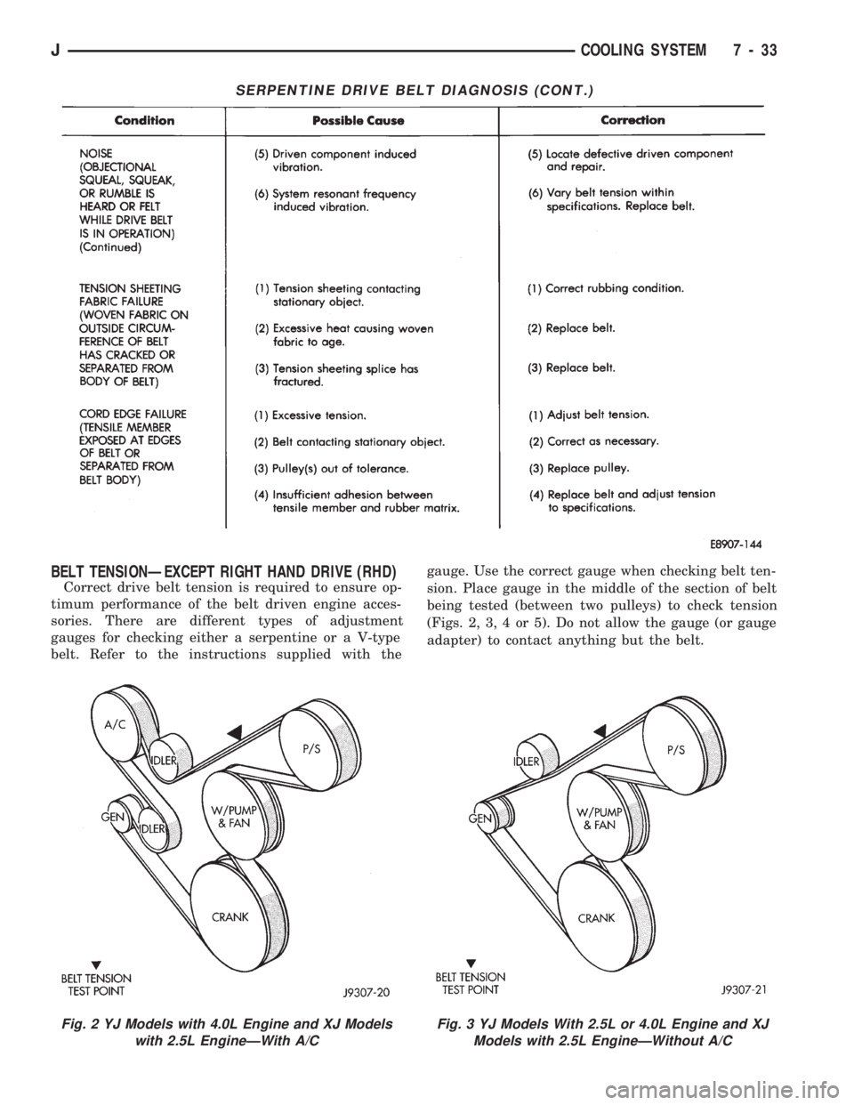
BELT TENSIONÐEXCEPT RIGHT HAND DRIVE (RHD)
Correct drive belt tension is required to ensure op-
timum performance of the belt driven engine acces-
sories. There are different types of adjustment
gauges for checking either a serpentine or a V-type
belt. Refer to the instructions supplied with thegauge. Use the correct gauge when checking belt ten-
sion. Place gauge in the middle of the section of belt
being tested (between two pulleys) to check tension
(Figs. 2, 3, 4 or 5). Do not allow the gauge (or gauge
adapter) to contact anything but the belt.
SERPENTINE DRIVE BELT DIAGNOSIS (CONT.)
Fig. 2 YJ Models with 4.0L Engine and XJ Models
with 2.5L EngineÐWith A/CFig. 3 YJ Models With 2.5L or 4.0L Engine and XJ
Models with 2.5L EngineÐWithout A/C
JCOOLING SYSTEM 7 - 33
Page 267 of 1784
BELT TENSIONÐRIGHT HAND DRIVE (RHD)
XJ MODELS WITH 4.0L ENGINE
It is not necessary to adjust belt tension on RHD
vehicles if equipped with a 4.0L engine. The engine
is equipped with an automatic belt tensioner (Fig. 7).
The tensioner maintains correct belt tension at all
times.Due to the use of this belt tensioner, DO
NOT attempt to use a belt tension gauge on this
engine.
BELT TENSION SPECIFICATIONS
Refer to the Specifications section at the end of this
group.
BELT SCHEMATICS
The belt routing schematics are published from the
latest information available at the time of publica-
tion.If anything differs between these schemat-
ics and the Belt Routing Label, use the
schematics on Belt Routing Label.This label is lo-
cated in the engine compartment.
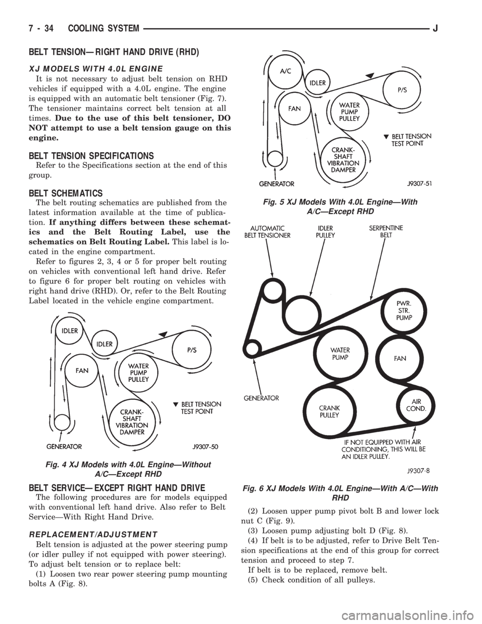
Refer to figures 2, 3, 4 or 5 for proper belt routing
on vehicles with conventional left hand drive. Refer
to figure 6 for proper belt routing on vehicles with
right hand drive (RHD). Or, refer to the Belt Routing
Label located in the vehicle engine compartment.
BELT SERVICEÐEXCEPT RIGHT HAND DRIVE
The following procedures are for models equipped
with conventional left hand drive. Also refer to Belt
ServiceÐWith Right Hand Drive.
REPLACEMENT/ADJUSTMENT
Belt tension is adjusted at the power steering pump
(or idler pulley if not equipped with power steering).
To adjust belt tension or to replace belt:
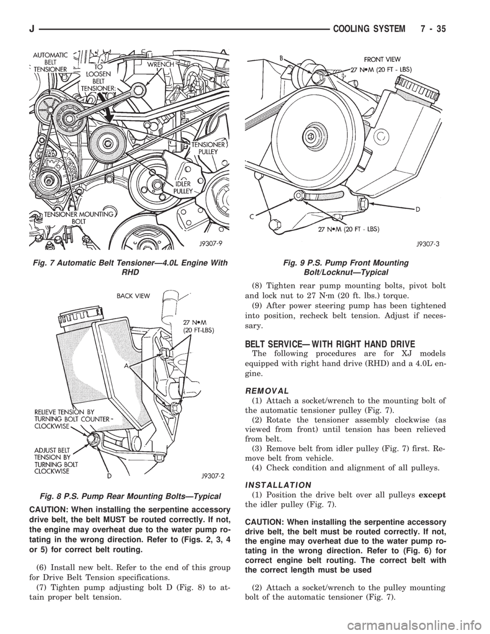
(1) Loosen two rear power steering pump mounting
bolts A (Fig. 8).(2) Loosen upper pump pivot bolt B and lower lock
nut C (Fig. 9).
(3) Loosen pump adjusting bolt D (Fig. 8).
(4) If belt is to be adjusted, refer to Drive Belt Ten-
sion specifications at the end of this group for correct
tension and proceed to step 7.
If belt is to be replaced, remove belt.
(5) Check condition of all pulleys.
Fig. 4 XJ Models with 4.0L EngineÐWithout
A/CÐExcept RHD
Fig. 5 XJ Models With 4.0L EngineÐWith
A/CÐExcept RHD
Fig. 6 XJ Models With 4.0L EngineÐWith A/CÐWith
RHD
7 - 34 COOLING SYSTEMJ
Page 268 of 1784
CAUTION: When installing the serpentine accessory
drive belt, the belt MUST be routed correctly. If not,
the engine may overheat due to the water pump ro-
tating in the wrong direction. Refer to (Figs. 2, 3, 4
or 5) for correct belt routing.
(6) Install new belt. Refer to the end of this group
for Drive Belt Tension specifications.
(7) Tighten pump adjusting bolt D (Fig. 8) to at-
tain proper belt tension.(8) Tighten rear pump mounting bolts, pivot bolt
and lock nut to 27 Nzm (20 ft. lbs.) torque.
(9) After power steering pump has been tightened
into position, recheck belt tension. Adjust if neces-
sary.
BELT SERVICEÐWITH RIGHT HAND DRIVE
The following procedures are for XJ models
equipped with right hand drive (RHD) and a 4.0L en-
gine.
REMOVAL
(1) Attach a socket/wrench to the mounting bolt of
the automatic tensioner pulley (Fig. 7).
(2) Rotate the tensioner assembly clockwise (as
viewed from front) until tension has been relieved
from belt.
(3) Remove belt from idler pulley (Fig. 7) first. Re-
move belt from vehicle.
(4) Check condition and alignment of all pulleys.
INSTALLATION
(1) Position the drive belt over all pulleysexcept
the idler pulley (Fig. 7).
CAUTION: When installing the serpentine accessory
drive belt, the belt must be routed correctly. If not,
the engine may overheat due to the water pump ro-
tating in the wrong direction. Refer to (Fig. 6) for
correct engine belt routing. The correct belt with
the correct length must be used
(2) Attach a socket/wrench to the pulley mounting
bolt of the automatic tensioner (Fig. 7).
Fig. 7 Automatic Belt TensionerÐ4.0L Engine With
RHD
Fig. 8 P.S. Pump Rear Mounting BoltsÐTypical
Fig. 9 P.S. Pump Front Mounting
Bolt/LocknutÐTypical
JCOOLING SYSTEM 7 - 35
Page 269 of 1784
(3) Rotate the socket/wrench clockwise (Fig. 7).
Place the belt over the idler pulley. Let tensioner ro-
tate back into place. Remove wrench. Be sure belt is
properly seated in the grooves of all pulleys.
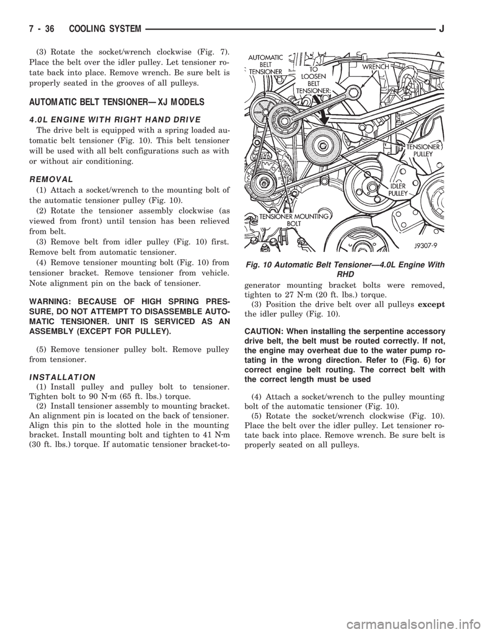
AUTOMATIC BELT TENSIONERÐXJ MODELS
4.0L ENGINE WITH RIGHT HAND DRIVE
The drive belt is equipped with a spring loaded au-
tomatic belt tensioner (Fig. 10). This belt tensioner
will be used with all belt configurations such as with
or without air conditioning.
REMOVAL
(1) Attach a socket/wrench to the mounting bolt of
the automatic tensioner pulley (Fig. 10).
(2) Rotate the tensioner assembly clockwise (as
viewed from front) until tension has been relieved
from belt.
(3) Remove belt from idler pulley (Fig. 10) first.
Remove belt from automatic tensioner.
(4) Remove tensioner mounting bolt (Fig. 10) from
tensioner bracket. Remove tensioner from vehicle.
Note alignment pin on the back of tensioner.
WARNING: BECAUSE OF HIGH SPRING PRES-
SURE, DO NOT ATTEMPT TO DISASSEMBLE AUTO-
MATIC TENSIONER. UNIT IS SERVICED AS AN
ASSEMBLY (EXCEPT FOR PULLEY).
(5) Remove tensioner pulley bolt. Remove pulley
from tensioner.
INSTALLATION
(1) Install pulley and pulley bolt to tensioner.
Tighten bolt to 90 Nzm (65 ft. lbs.) torque.
(2) Install tensioner assembly to mounting bracket.
An alignment pin is located on the back of tensioner.
Align this pin to the slotted hole in the mounting
bracket. Install mounting bolt and tighten to 41 Nzm
(30 ft. lbs.) torque. If automatic tensioner bracket-to-generator mounting bracket bolts were removed,
tighten to 27 Nzm (20 ft. lbs.) torque.
(3) Position the drive belt over all pulleysexcept
the idler pulley (Fig. 10).
CAUTION: When installing the serpentine accessory
drive belt, the belt must be routed correctly. If not,
the engine may overheat due to the water pump ro-
tating in the wrong direction. Refer to (Fig. 6) for
correct engine belt routing. The correct belt with
the correct length must be used
(4) Attach a socket/wrench to the pulley mounting
bolt of the automatic tensioner (Fig. 10).
(5) Rotate the socket/wrench clockwise (Fig. 10).
Place the belt over the idler pulley. Let tensioner ro-
tate back into place. Remove wrench. Be sure belt is
properly seated on all pulleys.
Fig. 10 Automatic Belt TensionerÐ4.0L Engine With
RHD
7 - 36 COOLING SYSTEMJ
Page 270 of 1784
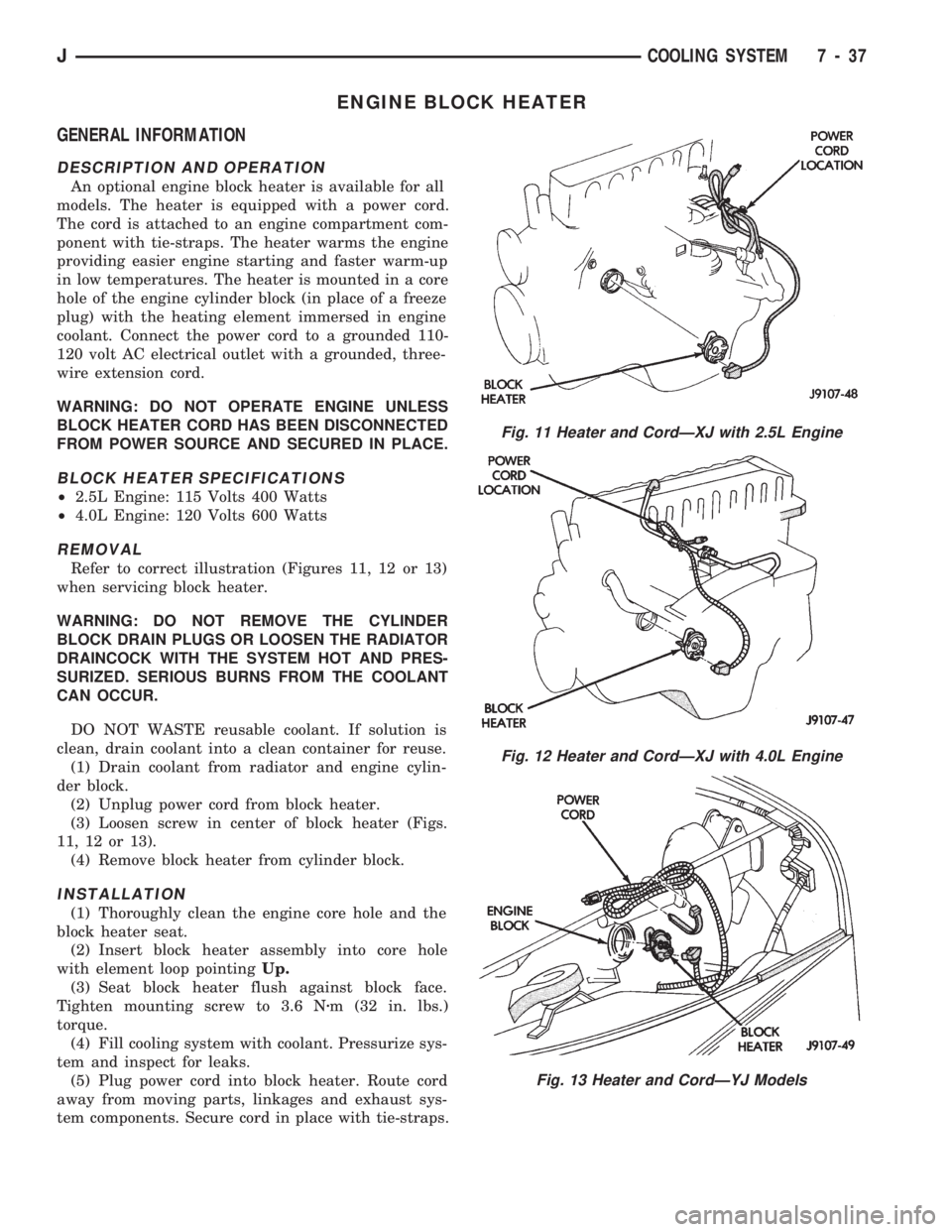
ENGINE BLOCK HEATER
GENERAL INFORMATION
DESCRIPTION AND OPERATION
An optional engine block heater is available for all
models. The heater is equipped with a power cord.
The cord is attached to an engine compartment com-
ponent with tie-straps. The heater warms the engine
providing easier engine starting and faster warm-up
in low temperatures. The heater is mounted in a core
hole of the engine cylinder block (in place of a freeze
plug) with the heating element immersed in engine
coolant. Connect the power cord to a grounded 110-
120 volt AC electrical outlet with a grounded, three-
wire extension cord.
WARNING: DO NOT OPERATE ENGINE UNLESS
BLOCK HEATER CORD HAS BEEN DISCONNECTED
FROM POWER SOURCE AND SECURED IN PLACE.
BLOCK HEATER SPECIFICATIONS
²2.5L Engine: 115 Volts 400 Watts
²4.0L Engine: 120 Volts 600 Watts
REMOVAL
Refer to correct illustration (Figures 11, 12 or 13)
when servicing block heater.
WARNING: DO NOT REMOVE THE CYLINDER
BLOCK DRAIN PLUGS OR LOOSEN THE RADIATOR
DRAINCOCK WITH THE SYSTEM HOT AND PRES-
SURIZED. SERIOUS BURNS FROM THE COOLANT
CAN OCCUR.
DO NOT WASTE reusable coolant. If solution is
clean, drain coolant into a clean container for reuse.
(1) Drain coolant from radiator and engine cylin-
der block.
(2) Unplug power cord from block heater.
(3) Loosen screw in center of block heater (Figs.
11, 12 or 13).
(4) Remove block heater from cylinder block.
INSTALLATION
(1) Thoroughly clean the engine core hole and the
block heater seat.
(2) Insert block heater assembly into core hole
with element loop pointingUp.
(3) Seat block heater flush against block face.
Tighten mounting screw to 3.6 Nzm (32 in. lbs.)
torque.
(4) Fill cooling system with coolant. Pressurize sys-
tem and inspect for leaks.
(5) Plug power cord into block heater. Route cord
away from moving parts, linkages and exhaust sys-
tem components. Secure cord in place with tie-straps.
Fig. 11 Heater and CordÐXJ with 2.5L Engine
Fig. 12 Heater and CordÐXJ with 4.0L Engine
Fig. 13 Heater and CordÐYJ Models
JCOOLING SYSTEM 7 - 37
Page 271 of 1784
SPECIFICATIONS
GENERAL INFORMATION
The following specifications are published from the
latest information available at the time of publica-
tion.If anything differs between the specifica-
tions found on the Vehicle Emission Control
Information (VECI) label and the following
specifications, use specifications on VECI label.
The VECI label is located in the engine compart-
ment.
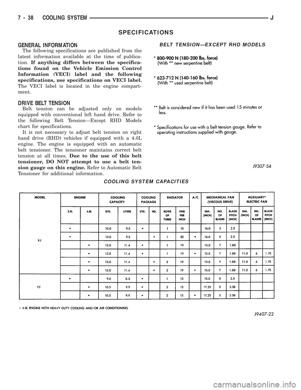
DRIVE BELT TENSION
Belt tension can be adjusted only on models
equipped with conventional left hand drive. Refer to
the following Belt TensionÐExcept RHD Models
chart for specifications.
It is not necessary to adjust belt tension on right
hand drive (RHD) vehicles if equipped with a 4.0L
engine. The engine is equipped with an automatic
belt tensioner. The tensioner maintains correct belt
tension at all times.Due to the use of this belt
tensioner, DO NOT attempt to use a belt ten-
sion gauge on this engine.Refer to Automatic Belt
Tensioner for additional information.
COOLING SYSTEM CAPACITIES
BELT TENSIONÐEXCEPT RHD MODELS
7 - 38 COOLING SYSTEMJ
Page 272 of 1784
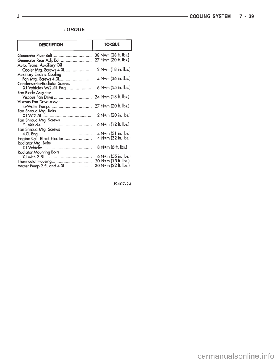
TORQUE
JCOOLING SYSTEM 7 - 39
Page 302 of 1784
CAUTION: Never force a belt over a pulley rim us-
ing a screwdriver as the synthetic fiber may be
damaged.
CAUTION: When installing a serpentine accessory
drive belt, the belt MUST be routed correctly. The
engine may overheat because the water pump will
be rotating in the wrong direction if the belt is in-
stalled incorrectly. Refer to the belt routing label in
engine compartment, or see Group 7 - Belt Sche-
matics.
(10) Place serpentine belt over pulley.
(11) Belt tension adjustment is made at power
steering pump (Fig. 6).
(12) Turn adjusting bolt until belt has correct ten-
sion. See Belt Tension in Specifications.
(13) Tighten rear mounting bolts, pivot bolt, and
lock nut to 27 Nzm (20 ft. lbs.) torque.
(14) Remove support and lower vehicle.
(15) Connect negative cable to battery.
GENERATOR REPLACEMENTÐRIGHT HAND DRIVE
The generator used on the right hand drive is the
same as used on left hand drive. However, the
mounting and accessory drive belt installation are
different.
WARNING: FAILURE TO DISCONNECT NEGATIVE
CABLE FROM BATTERY BEFORE DISCONNECTING
RED (OUTPUT) WIRE CONNECTOR FROM GENER-
ATOR CAN RESULT IN INJURY.
(1) Remove negative cable from battery.
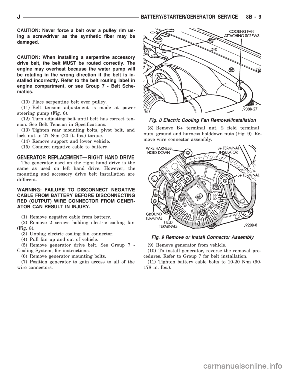
(2) Remove 2 screws holding electric cooling fan
(Fig. 8).
(3) Unplug electric cooling fan connector.
(4) Pull fan up and out of vehicle.
(5) Remove generator drive belt. See Group 7 -
Cooling System, for instructions.
(6) Remove generator mounting bolts.
(7) Position generator to gain access to all of the
wire connectors.(8) Remove B+ terminal nut, 2 field terminal
nuts, ground and harness holddown nuts (Fig. 9). Re-
move wire connector assembly.
(9) Remove generator from vehicle.
(10) To install generator, reverse the removal pro-
cedures. Refer to Group 7 for belt installation.
(11) Tighten battery cable bolts to 10-20 Nzm (90-
178 in. lbs.).
Fig. 8 Electric Cooling Fan Removal/Installation
Fig. 9 Remove or Install Connector Assembly
JBATTERY/STARTER/GENERATOR SERVICE 8B - 9