1994 JEEP CHEROKEE engine
[x] Cancel search: enginePage 1028 of 1784
²Have a 3 degree maximum operating angle
²Have at least a 1/2 degree continuous operating
(propeller shaft) angle
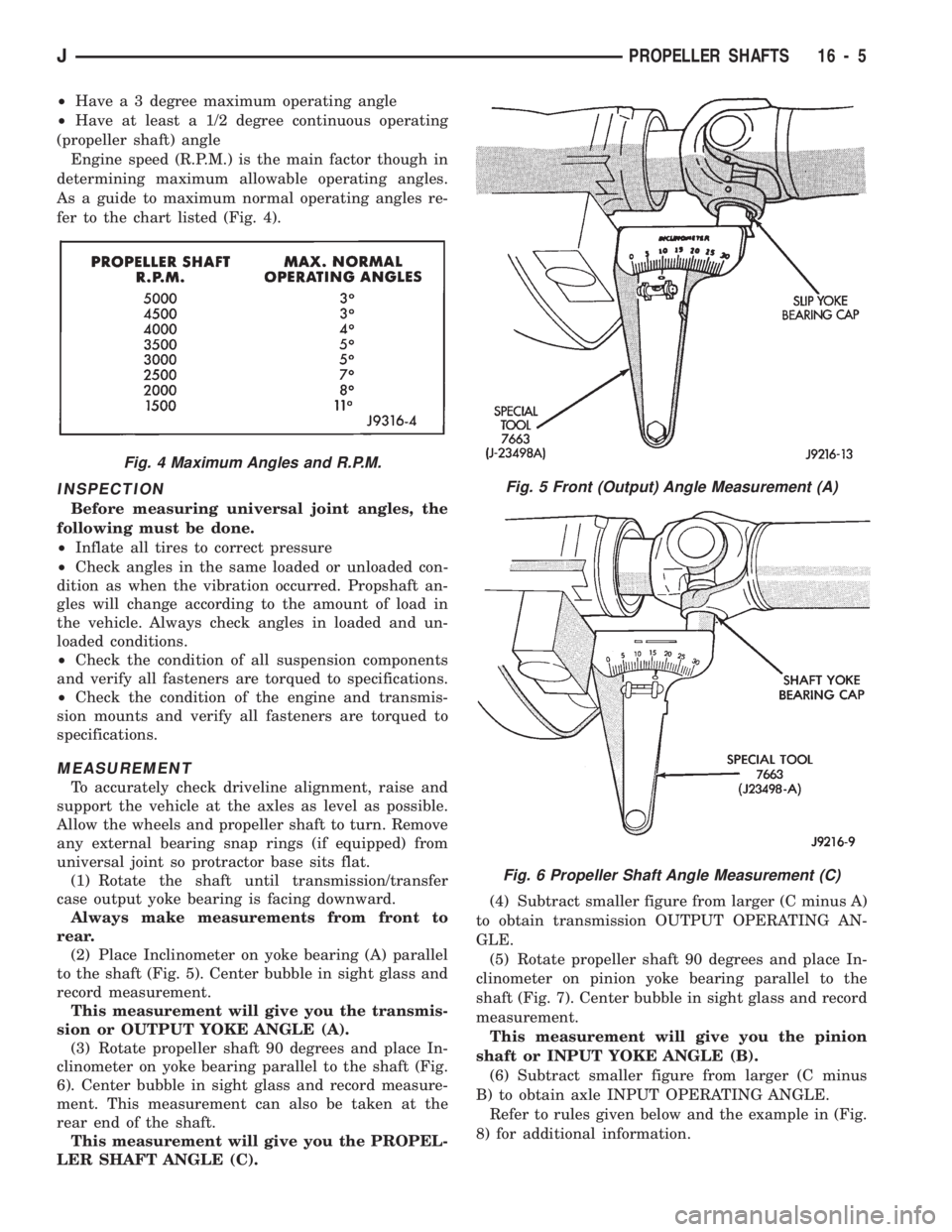
Engine speed (R.P.M.) is the main factor though in
determining maximum allowable operating angles.
As a guide to maximum normal operating angles re-
fer to the chart listed (Fig. 4).
INSPECTION
Before measuring universal joint angles, the
following must be done.
²Inflate all tires to correct pressure
²Check angles in the same loaded or unloaded con-
dition as when the vibration occurred. Propshaft an-
gles will change according to the amount of load in
the vehicle. Always check angles in loaded and un-
loaded conditions.
²Check the condition of all suspension components
and verify all fasteners are torqued to specifications.
²Check the condition of the engine and transmis-
sion mounts and verify all fasteners are torqued to
specifications.
MEASUREMENT
To accurately check driveline alignment, raise and
support the vehicle at the axles as level as possible.
Allow the wheels and propeller shaft to turn. Remove
any external bearing snap rings (if equipped) from
universal joint so protractor base sits flat.
(1) Rotate the shaft until transmission/transfer
case output yoke bearing is facing downward.
Always make measurements from front to
rear.
(2) Place Inclinometer on yoke bearing (A) parallel
to the shaft (Fig. 5). Center bubble in sight glass and
record measurement.
This measurement will give you the transmis-
sion or OUTPUT YOKE ANGLE (A).
(3) Rotate propeller shaft 90 degrees and place In-
clinometer on yoke bearing parallel to the shaft (Fig.
6). Center bubble in sight glass and record measure-
ment. This measurement can also be taken at the
rear end of the shaft.
This measurement will give you the PROPEL-
LER SHAFT ANGLE (C).(4) Subtract smaller figure from larger (C minus A)
to obtain transmission OUTPUT OPERATING AN-
GLE.
(5) Rotate propeller shaft 90 degrees and place In-
clinometer on pinion yoke bearing parallel to the
shaft (Fig. 7). Center bubble in sight glass and record
measurement.
This measurement will give you the pinion
shaft or INPUT YOKE ANGLE (B).
(6) Subtract smaller figure from larger (C minus
B) to obtain axle INPUT OPERATING ANGLE.
Refer to rules given below and the example in (Fig.
8) for additional information.
Fig. 4 Maximum Angles and R.P.M.
Fig. 5 Front (Output) Angle Measurement (A)
Fig. 6 Propeller Shaft Angle Measurement (C)
JPROPELLER SHAFTS 16 - 5
Page 1038 of 1784
STEERING
CONTENTS
page page
GENERAL INFORMATION.................. 1
MANUAL STEERING GEAR............... 35
NON-TILT STEERING COLUMN............ 50
POWER STEERING PUMP................. 9
POWER STEERING SYSTEM DIAGNOSIS..... 3
RECIRCULATING BALL POWER STEERING GEAR.19STEERING COLUMN GENERAL SERVICE.... 45
STEERING LINKAGEÐXJ................. 14
STEERING LINKAGEÐYJ................. 17
STEERING RHD........................ 69
TILT STEERING COLUMN................ 59
TORQUE SPECIFICATIONS................ 73
GENERAL INFORMATION
STEERING SYSTEM COMPONENTS
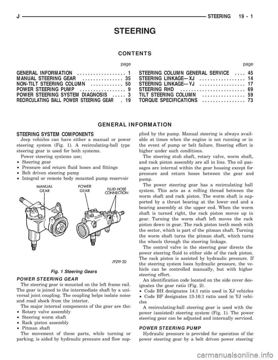
Jeep vehicles can have either a manual or power
steering system (Fig. 1). A recirculating-ball type
steering gear is used for both systems.
Power steering systems use;
²Steering gear
²Pressure and return fluid hoses and fittings
²Belt driven steering pump
²Integral or remote body mounted pump reservoir
POWER STEERING GEAR
The steering gear is mounted on the left frame rail.
The gear is joined to the intermediate shaft by a uni-
versal joint coupling. The coupling helps isolate noise
and road shock from the interior.
The major internal components of the gear are the:
²Rotary valve assembly
²Steering worm shaft
²Rack piston assembly
²Pitman shaft
The movement of these parts, while turning or
parking, is aided by hydraulic pressure and flow sup-plied by the pump. Manual steering is always avail-
able at times when the engine is not running or in
the event of pump or belt failure. Steering effort is
higher under such conditions.
The steering stub shaft, rotary valve, worm shaft,
and rack piston assembly are all in line. The oil pas-
sages are internal within the gear housing except for
pressure and return hoses between the gear and
pump.
The power steering gear has a recirculating ball
system. This acts as a rolling thread between the
worm shaft and rack piston. The worm shaft is sup-
ported by a thrust bearing at the lower end and a
bearing assembly at the upper end. When the worm
shaft is turned right, the rack piston moves up in
gear. Turning the worm shaft left moves the rack
piston down in gear. The rack piston teeth mesh with
the sector, which is part of the pitman shaft. Turning
the worm shaft turns the pitman shaft, which turns
the wheels through the steering linkage.
The control valve in the steering gear directs the
power steering fluid to either side of the rack piston.
The rack piston is assisted by hydraulic pressure. If
the steering system loses hydraulic pressure, the ve-
hicle can be controlled manually, but with higher
steering effort.
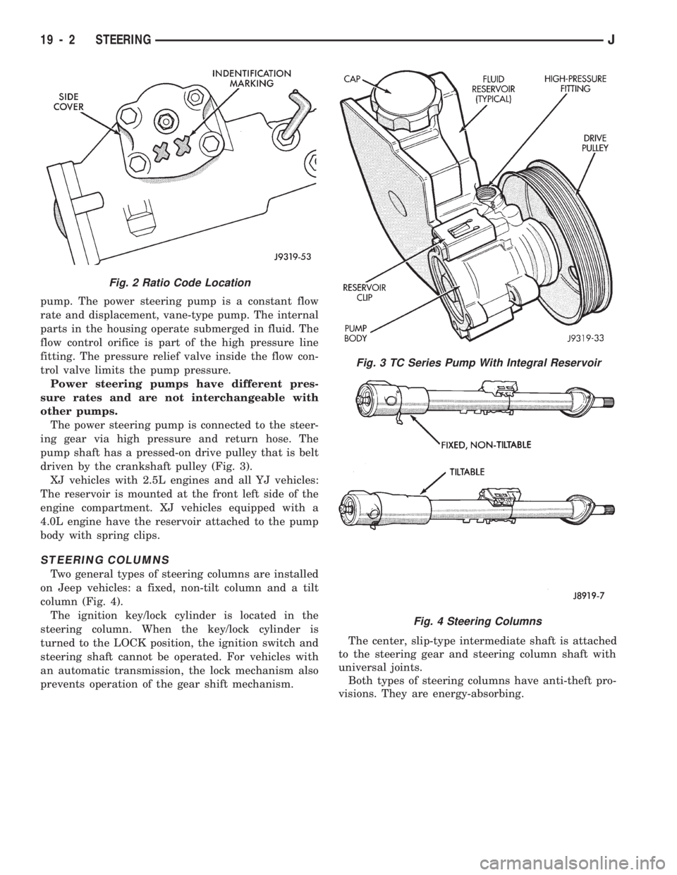
An identification code located on the side cover des-
ignates the gear ratio (Fig. 2).
²Code BH designates 14:1 ratio used in XJ vehicles
²Code BF designates 13-16:1 ratio used in YJ vehi-
cles
A recirculating-ball steering gear is used with the
power (assisted) steering system (Fig. 1). The power
steering gear can be adjusted and internally serviced.
POWER STEERING PUMP
Hydraulic pressure is provided for operation of the
power steering gear by a belt driven power steering
Fig. 1 Steering Gears
JSTEERING 19 - 1
Page 1039 of 1784
pump. The power steering pump is a constant flow
rate and displacement, vane-type pump. The internal
parts in the housing operate submerged in fluid. The
flow control orifice is part of the high pressure line
fitting. The pressure relief valve inside the flow con-
trol valve limits the pump pressure.
Power steering pumps have different pres-
sure rates and are not interchangeable with
other pumps.
The power steering pump is connected to the steer-
ing gear via high pressure and return hose. The
pump shaft has a pressed-on drive pulley that is belt
driven by the crankshaft pulley (Fig. 3).
XJ vehicles with 2.5L engines and all YJ vehicles:
The reservoir is mounted at the front left side of the
engine compartment. XJ vehicles equipped with a
4.0L engine have the reservoir attached to the pump
body with spring clips.
STEERING COLUMNS
Two general types of steering columns are installed
on Jeep vehicles: a fixed, non-tilt column and a tilt
column (Fig. 4).
The ignition key/lock cylinder is located in the
steering column. When the key/lock cylinder is
turned to the LOCK position, the ignition switch and
steering shaft cannot be operated. For vehicles with
an automatic transmission, the lock mechanism also
prevents operation of the gear shift mechanism.The center, slip-type intermediate shaft is attached
to the steering gear and steering column shaft with
universal joints.
Both types of steering columns have anti-theft pro-
visions. They are energy-absorbing.
Fig. 3 TC Series Pump With Integral Reservoir
Fig. 4 Steering Columns
Fig. 2 Ratio Code Location
19 - 2 STEERINGJ
Page 1040 of 1784
POWER STEERING SYSTEM DIAGNOSIS
PUMP PRESSURE TEST
(1) Check belt tension and adjust as necessary.
(2) Disconnect high pressure hose at gear or pump.
Use a container for dripping fluid.
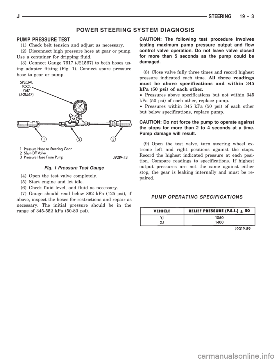
(3) Connect Gauge 7617 (J21567) to both hoses us-
ing adapter fitting (Fig. 1). Connect spare pressure
hose to gear or pump.
(4) Open the test valve completely.
(5) Start engine and let idle.
(6) Check fluid level, add fluid as necessary.
(7) Gauge should read below 862 kPa (125 psi), if
above, inspect the hoses for restrictions and repair as
necessary. The initial pressure should be in the
range of 345-552 kPa (50-80 psi).CAUTION: The following test procedure involves
testing maximum pump pressure output and flow
control valve operation. Do not leave valve closed
for more than 5 seconds as the pump could be
damaged.
(8) Close valve fully three times and record highest
pressure indicated each time.All three readings
must be above specifications and within 345
kPa (50 psi) of each other.
²Pressures above specifications but not within 345
kPa (50 psi) of each other, replace pump.
²Pressures within 345 kPa (50 psi) of each other
but below specifications, replace pump.
CAUTION: Do not force the pump to operate against
the stops for more than 2 to 4 seconds at a time.
Pump damage will result.
(9) Open the test valve, turn steering wheel ex-
treme left and right positions against the stops.
Record the highest indicated pressure at each posi-
tion. Compare readings to specifications. If highest
output pressures are not the same against either
stop, the gear is leaking internally and must be re-
paired.
Fig. 1 Pressure Test Gauge
PUMP OPERATING SPECIFICATIONS
JSTEERING 19 - 3
Page 1046 of 1784
POWER STEERING PUMP
INDEX
page page
Drive Pulley Replacement.................. 11
Flow Control Valve Fitting O-Ring Seal........ 12
Power Steering PumpÐInitial Operation....... 13
Pressure and Return Hose Replacement........ 9Pump Replacement....................... 10
Reservoir Replacement.................... 12
Service Information........................ 9
SERVICE INFORMATION
The power steering pump internal components are
not serviced or adjusted. If a malfunction or an inter-
nal fluid leak occurs, the complete unit must be re-
placed. A reservoir, cap, and O-ring seal kit are the
only service components available.
PRESSURE AND RETURN HOSE REPLACEMENT
Cap hose open ends and pump/steering gear fit-
tings to prevent entry of foreign material.
WARNING: POWER STEERING FLUID (AND PUMP
COMPONENTS) AND THE EXHAUST SYSTEM CAN
BE EXTREMELY HOT IF THE ENGINE HAS BEEN
RECENTLY OPERATING. DO NOT START THE EN-
GINE WITH ANY LOOSE OR DISCONNECTED
HOSES. DO NOT ALLOW THE HOSES TO TOUCH A
HOT EXHAUST MANIFOLD OR THE CATALYTIC
CONVERTER.
REMOVAL
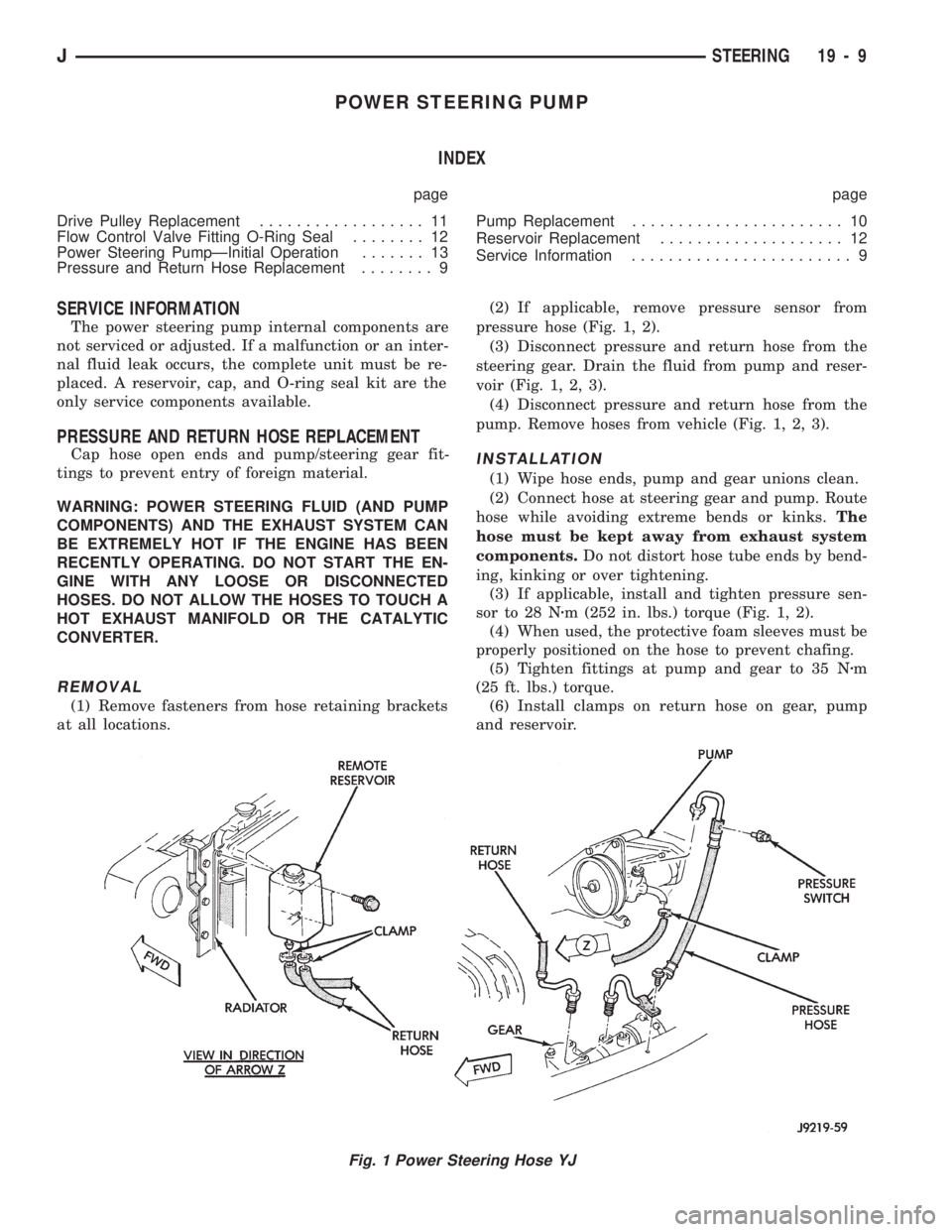
(1) Remove fasteners from hose retaining brackets
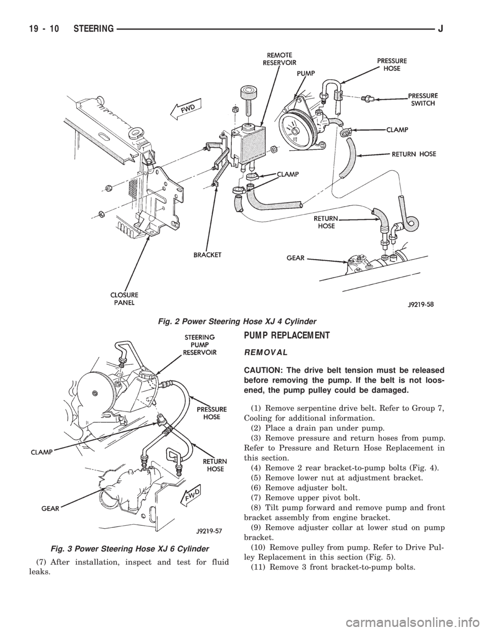
at all locations.(2) If applicable, remove pressure sensor from
pressure hose (Fig. 1, 2).
(3) Disconnect pressure and return hose from the
steering gear. Drain the fluid from pump and reser-
voir (Fig. 1, 2, 3).
(4) Disconnect pressure and return hose from the
pump. Remove hoses from vehicle (Fig. 1, 2, 3).
INSTALLATION
(1) Wipe hose ends, pump and gear unions clean.
(2) Connect hose at steering gear and pump. Route
hose while avoiding extreme bends or kinks.The
hose must be kept away from exhaust system
components.Do not distort hose tube ends by bend-
ing, kinking or over tightening.
(3) If applicable, install and tighten pressure sen-
sor to 28 Nzm (252 in. lbs.) torque (Fig. 1, 2).
(4) When used, the protective foam sleeves must be
properly positioned on the hose to prevent chafing.
(5) Tighten fittings at pump and gear to 35 Nzm
(25 ft. lbs.) torque.
(6) Install clamps on return hose on gear, pump
and reservoir.
Fig. 1 Power Steering Hose YJ
JSTEERING 19 - 9
Page 1047 of 1784
(7) After installation, inspect and test for fluid
leaks.
PUMP REPLACEMENT
REMOVAL
CAUTION: The drive belt tension must be released
before removing the pump. If the belt is not loos-
ened, the pump pulley could be damaged.
(1) Remove serpentine drive belt. Refer to Group 7,
Cooling for additional information.
(2) Place a drain pan under pump.
(3) Remove pressure and return hoses from pump.
Refer to Pressure and Return Hose Replacement in
this section.
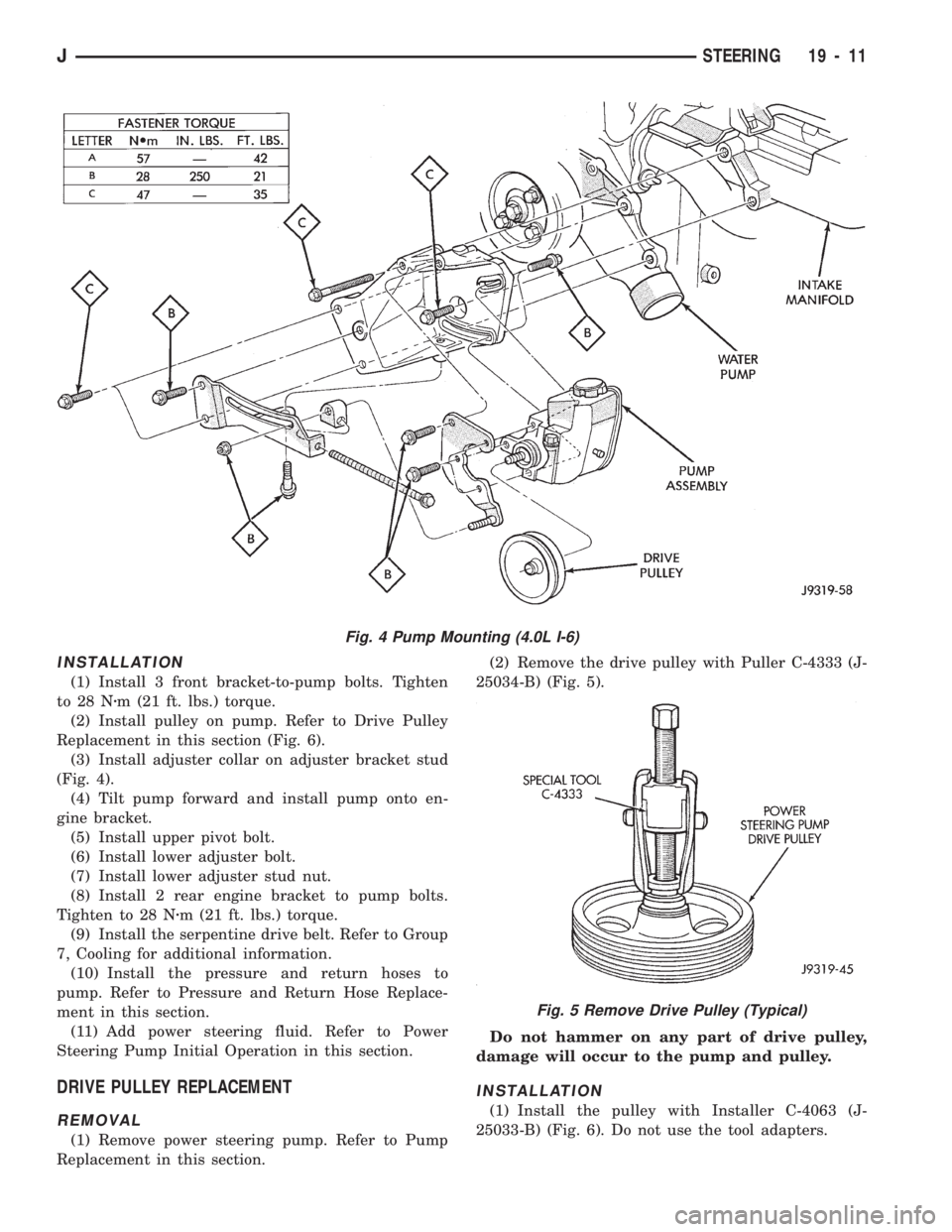
(4) Remove 2 rear bracket-to-pump bolts (Fig. 4).
(5) Remove lower nut at adjustment bracket.
(6) Remove adjuster bolt.
(7) Remove upper pivot bolt.
(8) Tilt pump forward and remove pump and front
bracket assembly from engine bracket.
(9) Remove adjuster collar at lower stud on pump
bracket.
(10) Remove pulley from pump. Refer to Drive Pul-
ley Replacement in this section (Fig. 5).
(11) Remove 3 front bracket-to-pump bolts.
Fig. 2 Power Steering Hose XJ 4 Cylinder
Fig. 3 Power Steering Hose XJ 6 Cylinder
19 - 10 STEERINGJ
Page 1048 of 1784
INSTALLATION
(1) Install 3 front bracket-to-pump bolts. Tighten
to 28 Nzm (21 ft. lbs.) torque.
(2) Install pulley on pump. Refer to Drive Pulley
Replacement in this section (Fig. 6).
(3) Install adjuster collar on adjuster bracket stud
(Fig. 4).
(4) Tilt pump forward and install pump onto en-
gine bracket.
(5) Install upper pivot bolt.
(6) Install lower adjuster bolt.
(7) Install lower adjuster stud nut.
(8) Install 2 rear engine bracket to pump bolts.
Tighten to 28 Nzm (21 ft. lbs.) torque.
(9) Install the serpentine drive belt. Refer to Group
7, Cooling for additional information.
(10) Install the pressure and return hoses to
pump. Refer to Pressure and Return Hose Replace-
ment in this section.
(11) Add power steering fluid. Refer to Power
Steering Pump Initial Operation in this section.
DRIVE PULLEY REPLACEMENT
REMOVAL
(1) Remove power steering pump. Refer to Pump
Replacement in this section.(2) Remove the drive pulley with Puller C-4333 (J-
25034-B) (Fig. 5).
Do not hammer on any part of drive pulley,
damage will occur to the pump and pulley.
INSTALLATION
(1) Install the pulley with Installer C-4063 (J-
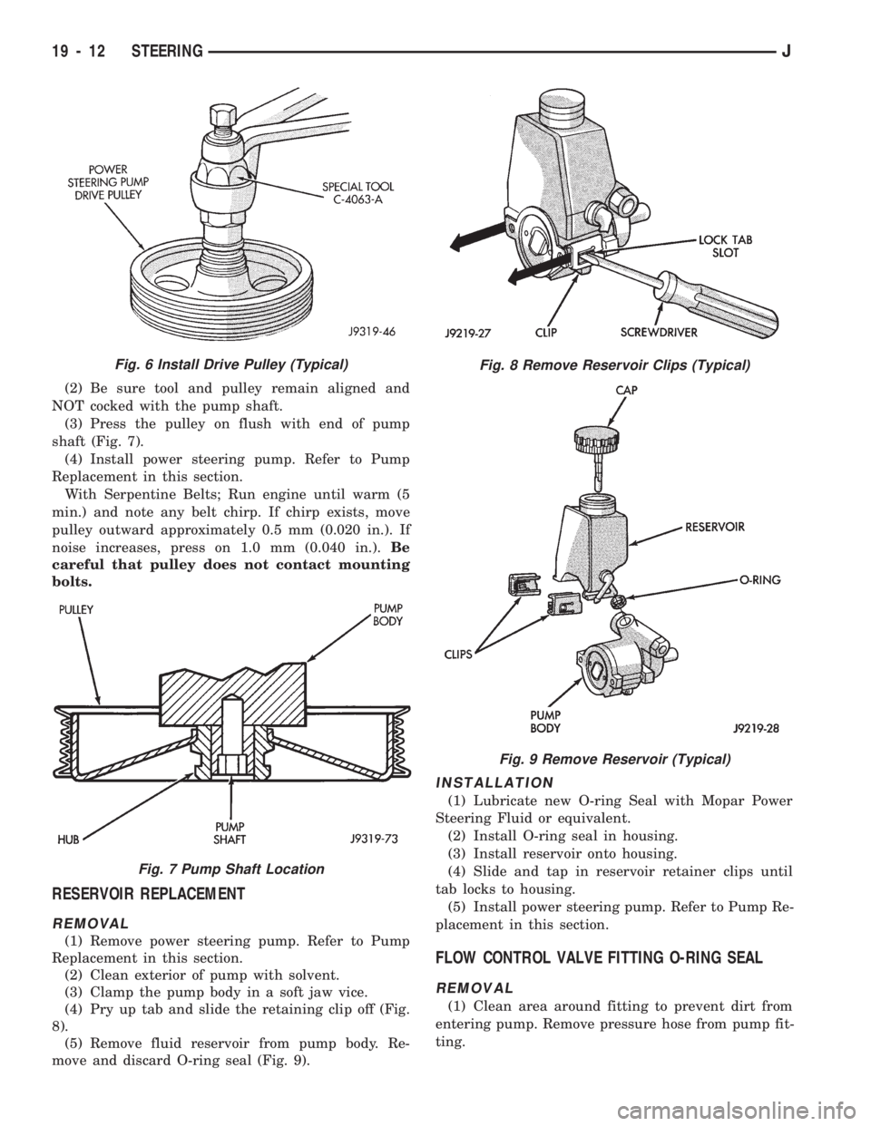
25033-B) (Fig. 6). Do not use the tool adapters.
Fig. 4 Pump Mounting (4.0L I-6)
Fig. 5 Remove Drive Pulley (Typical)
JSTEERING 19 - 11
Page 1049 of 1784
(2) Be sure tool and pulley remain aligned and
NOT cocked with the pump shaft.
(3) Press the pulley on flush with end of pump
shaft (Fig. 7).
(4) Install power steering pump. Refer to Pump
Replacement in this section.
With Serpentine Belts; Run engine until warm (5
min.) and note any belt chirp. If chirp exists, move
pulley outward approximately 0.5 mm (0.020 in.). If
noise increases, press on 1.0 mm (0.040 in.).Be
careful that pulley does not contact mounting
bolts.
RESERVOIR REPLACEMENT
REMOVAL
(1) Remove power steering pump. Refer to Pump
Replacement in this section.
(2) Clean exterior of pump with solvent.
(3) Clamp the pump body in a soft jaw vice.
(4) Pry up tab and slide the retaining clip off (Fig.
8).
(5) Remove fluid reservoir from pump body. Re-
move and discard O-ring seal (Fig. 9).
INSTALLATION
(1) Lubricate new O-ring Seal with Mopar Power
Steering Fluid or equivalent.
(2) Install O-ring seal in housing.
(3) Install reservoir onto housing.
(4) Slide and tap in reservoir retainer clips until
tab locks to housing.
(5) Install power steering pump. Refer to Pump Re-
placement in this section.
FLOW CONTROL VALVE FITTING O-RING SEAL
REMOVAL
(1) Clean area around fitting to prevent dirt from
entering pump. Remove pressure hose from pump fit-
ting.
Fig. 8 Remove Reservoir Clips (Typical)
Fig. 9 Remove Reservoir (Typical)
Fig. 6 Install Drive Pulley (Typical)
Fig. 7 Pump Shaft Location
19 - 12 STEERINGJ