1994 JEEP CHEROKEE ignition
[x] Cancel search: ignitionPage 140 of 1784
REMOVAL
(1) Disconnect the electrical connector from the
sensor.
(2) Remove the sensor from the intake manifold.
INSTALLATION
(1) Install the sensor into the intake manifold.
Tighten the sensor to 28 Nzm (20 ft. lbs.) torque.
(2) Connect the electrical connector to the sensor.
CRANKSHAFT POSITION SENSOR
For description, operation and removal/installation
procedures, refer to Group 8D, Ignition Systems in
this manual.
ENGINE COOLANT TEMPERATURE SENSOR
The coolant temperature sensor is installed in the
thermostat housing (Fig. 5).
REMOVAL
(1) Drain cooling system until the coolant level is
below the cylinder head. Observe theWARNINGSin
Group 7, Cooling.(2) Disconnect the coolant temperature sensor wire
connector.
(3) Remove the sensor from the thermostat hous-
ing (Fig. 5).
INSTALLATION
(1) Install coolant temperature sensor into the cyl-
inder block. Tighten to 28 Nzm (21 ft. lbs.) torque.
(2) Connect the wire connector.
(3) Fill the cooling system. Refer to Group 7, Cool-
ing System.
FUEL FILTER
Refer to the Fuel Delivery System section of this
group for removal/installation procedures.
FUEL INJECTOR
REMOVAL
(1) Remove the fuel rail. Refer to Fuel Rail Re-
moval in this section.
(2) Remove the clip(s) that retain the fuel injec-
tor(s) to the fuel rail (Fig. 6).
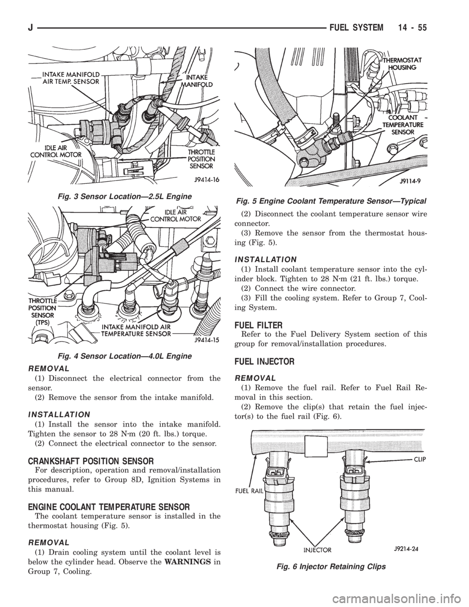
Fig. 3 Sensor LocationÐ2.5L Engine
Fig. 4 Sensor LocationÐ4.0L Engine
Fig. 5 Engine Coolant Temperature SensorÐTypical
Fig. 6 Injector Retaining Clips
JFUEL SYSTEM 14 - 55
Page 142 of 1784
REMOVAL
(1) Disconnect the electrical connector from the
IAC motor.
(2) Remove IAC motor torx head mounting bolts.
(3) Remove IAC motor.
INSTALLATION
(1) Install IAC motor into throttle body and
tighten retaining bolts.
(2) Connect electrical connector to IAC motor.
IGNITION COIL
Refer to Group 8D, Ignition Systems for removal/
installation procedures.
INTAKE MANIFOLD
Refer to Group 11, Exhaust System and Intake
Manifold for removal/installation procedures.
MANIFOLD ABSOLUTE PRESSURE (MAP) SENSOR
The MAP sensor is located on the dash panel near
the rear of the engine cylinder head (valve) cover
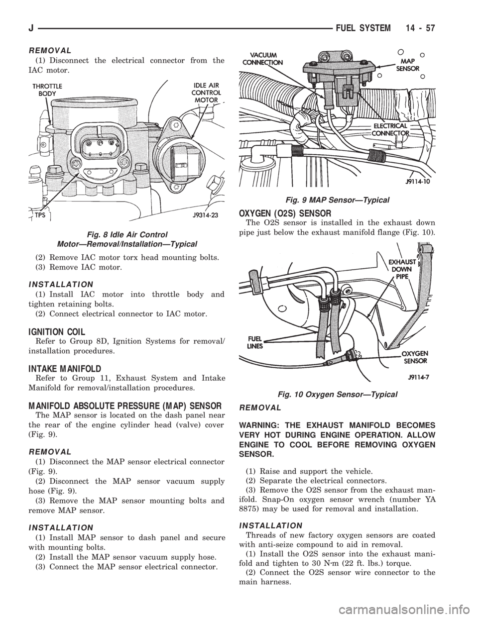
(Fig. 9).
REMOVAL
(1) Disconnect the MAP sensor electrical connector
(Fig. 9).
(2) Disconnect the MAP sensor vacuum supply
hose (Fig. 9).
(3) Remove the MAP sensor mounting bolts and
remove MAP sensor.
INSTALLATION
(1) Install MAP sensor to dash panel and secure
with mounting bolts.
(2) Install the MAP sensor vacuum supply hose.
(3) Connect the MAP sensor electrical connector.
OXYGEN (O2S) SENSOR
The O2S sensor is installed in the exhaust down
pipe just below the exhaust manifold flange (Fig. 10).
REMOVAL
WARNING: THE EXHAUST MANIFOLD BECOMES
VERY HOT DURING ENGINE OPERATION. ALLOW
ENGINE TO COOL BEFORE REMOVING OXYGEN
SENSOR.
(1) Raise and support the vehicle.
(2) Separate the electrical connectors.
(3) Remove the O2S sensor from the exhaust man-
ifold. Snap-On oxygen sensor wrench (number YA
8875) may be used for removal and installation.
INSTALLATION
Threads of new factory oxygen sensors are coated
with anti-seize compound to aid in removal.
(1) Install the O2S sensor into the exhaust mani-
fold and tighten to 30 Nzm (22 ft. lbs.) torque.
(2) Connect the O2S sensor wire connector to the
main harness.
Fig. 8 Idle Air Control
MotorÐRemoval/InstallationÐTypical
Fig. 9 MAP SensorÐTypical
Fig. 10 Oxygen SensorÐTypical
JFUEL SYSTEM 14 - 57
Page 158 of 1784
assembled, they will not function. In addition, since
the adjuster mechanism only works during reverse
stops, it is important that complete stops be made.
The adjuster mechanism does not operate when roll-
ing stops are made in reverse. The vehicle must be
brought to a complete halt before the adjuster lever
will turn the adjuster screw.
A condition where the parking brakes do not hold,
will most probably be due to a wheel brake compo-
nent.
Items to look for when diagnosing a parking brake
problem, are:
²rear brakeshoe wear
²rear brakedrum wear
²brakedrums machined beyond allowable diameter
(oversize)
²parking brake front cable not secured to lever
²parking brake rear cable seized
²parking brake strut reversed
²parking brake strut not seated in both shoes
²parking brake lever not seated in secondary shoe
²parking brake lever or brakeshoe bind on support
plate
²brakeshoes reversed
²adjuster screws seized
²adjuster screws reversed
²holddown or return springs misassembled or lack
tension
²wheel cylinder pistons seized
Brake drums that are machined oversize are diffi-
cult to identify. If oversize drums are suspected, the
diameter of the braking surface will have to be
checked with an accurate drum gauge. Oversize
drums will cause low brake pedal and lack of park-
ing brake holding ability.
Improper parking brake strut and lever installa-
tion will result in unsatisfactory parking brake oper-
ation. Intermixing the adjuster screws will cause
drag, bind and pull along with poor parking brake
operation.
Parking brake adjustment and parts replacement
procedures are described in the Parking Brake sec-
tion.
MASTER CYLINDER/POWER BOOSTER TEST
(1) Start engine and check booster vacuum hose
connections. Hissing noise indicates vacuum leak.
Correct any vacuum leak before proceeding.
(2) Stop engine and shift transmission into Neu-
tral.
(3) Pump brake pedal until all vacuum reserve in
booster is depleted.
(4) Press and hold brake pedal under light foot
pressure.
(a) If pedal holds firm, proceed to step (5).
(b) If pedal does not hold firm and falls away,
master cylinder is faulty (internal leakage). Over-
haul or replace cylinder.(5) Start engine and note pedal action.
(a) If pedal falls away slightly under light foot
pressure then holds firm, proceed to step (6).
(b) If no pedal action is discernible, power
booster or vacuum check valve is faulty. Install
known good check valve and repeat steps (2)
through (5).
(6) Rebuild booster vacuum reserve as follows: Re-
lease brake pedal. Increase engine speed to 1500
rpm, close throttle and immediately turn off ignition.
(7) Wait a minimum of 90 seconds and try brake
action again. Booster should provide two or more
vacuum assisted pedal applications. If vacuum assist
is not provided, perform booster and check valve vac-
uum tests.
POWER BOOSTER CHECK VALVE TEST
(1) Disconnect vacuum hose from check valve.
(2) Remove check valve and valve seal from
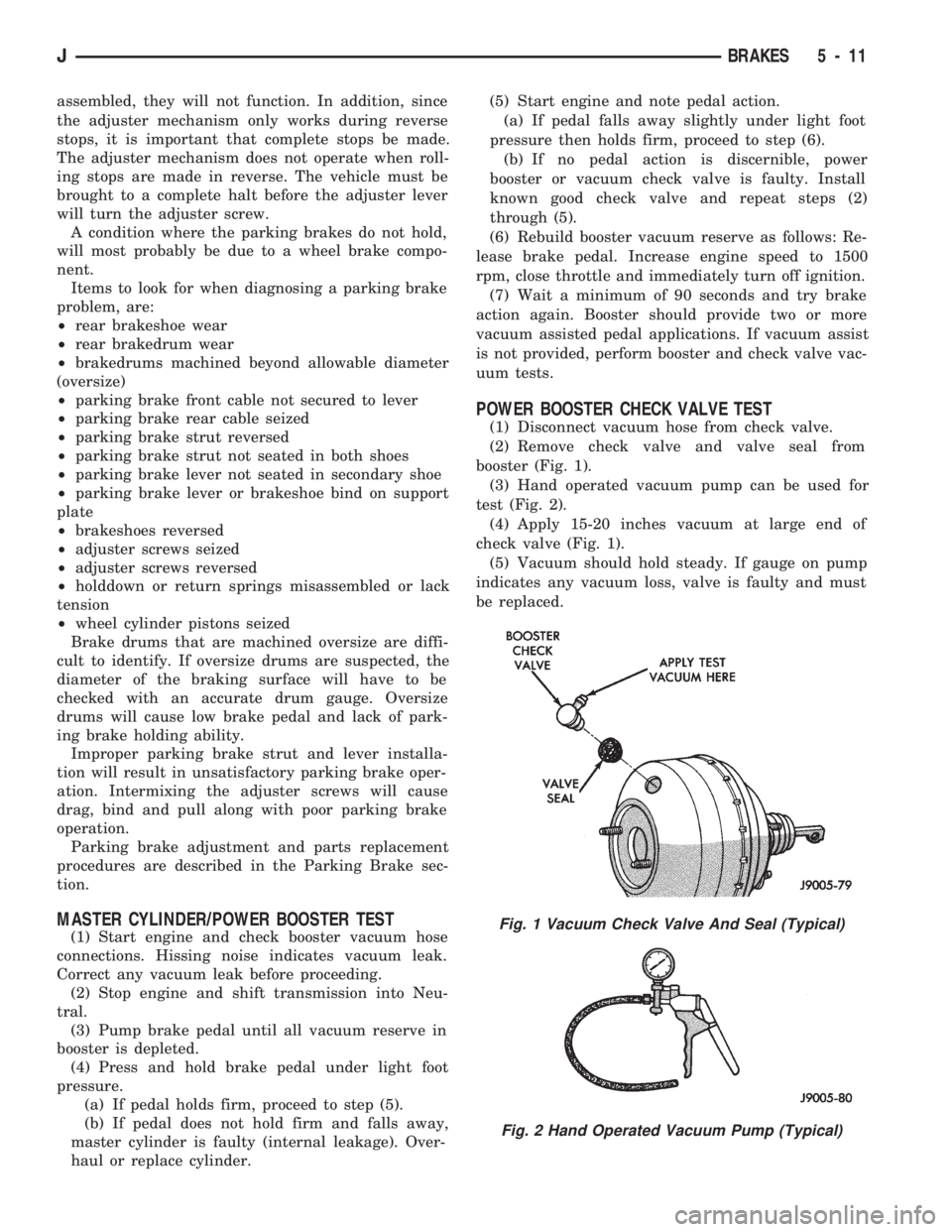
booster (Fig. 1).
(3) Hand operated vacuum pump can be used for
test (Fig. 2).
(4) Apply 15-20 inches vacuum at large end of
check valve (Fig. 1).
(5) Vacuum should hold steady. If gauge on pump
indicates any vacuum loss, valve is faulty and must
be replaced.
Fig. 1 Vacuum Check Valve And Seal (Typical)
Fig. 2 Hand Operated Vacuum Pump (Typical)
JBRAKES 5 - 11
Page 186 of 1784
ABS SYSTEM OPERATION
INDEX
page page
Acceleration Switch....................... 41
Combination Valve....................... 42
Electronic Control Unit (ECU)............... 41
General Information....................... 39
Hydraulic Control Unit (HCU)................ 39
Ignition Switch........................... 42Master Cylinder.......................... 40
Pedal Travel Sensor...................... 41
Power Brake Booster..................... 40
System Relays.......................... 42
System Warning Lights.................... 42
Wheel Speed Sensors..................... 41
GENERAL INFORMATION
The Jeep antilock brake system (ABS) is an elec-
tronically operated, all-wheel brake control system.
Major components include the master cylinder, vac-
uum power brake booster, ECU, hydraulic control
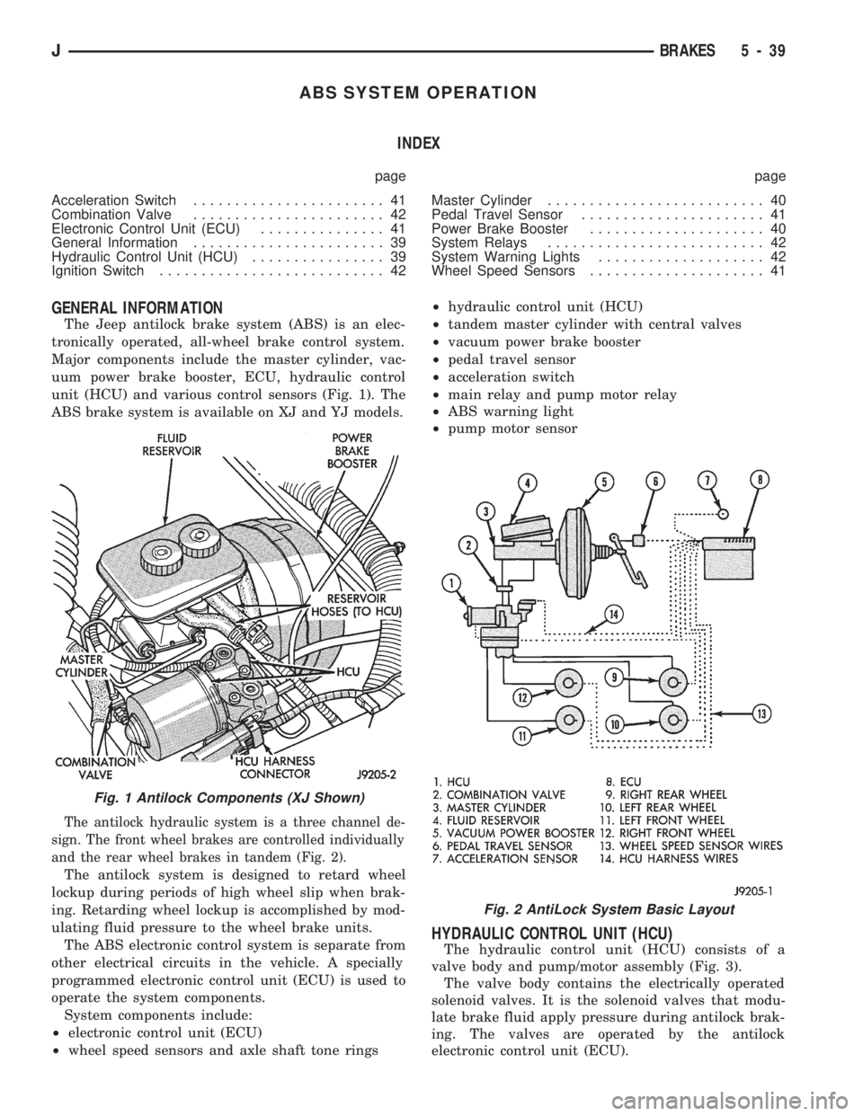
unit (HCU) and various control sensors (Fig. 1). The
ABS brake system is available on XJ and YJ models.
The antilock hydraulic system is a three channel de-
sign. The front wheel brakes are controlled individually
and the rear wheel brakes in tandem (Fig. 2).
The antilock system is designed to retard wheel
lockup during periods of high wheel slip when brak-
ing. Retarding wheel lockup is accomplished by mod-
ulating fluid pressure to the wheel brake units.
The ABS electronic control system is separate from
other electrical circuits in the vehicle. A specially
programmed electronic control unit (ECU) is used to
operate the system components.
System components include:
²electronic control unit (ECU)
²wheel speed sensors and axle shaft tone rings²hydraulic control unit (HCU)
²tandem master cylinder with central valves
²vacuum power brake booster
²pedal travel sensor
²acceleration switch
²main relay and pump motor relay
²ABS warning light
²pump motor sensor
HYDRAULIC CONTROL UNIT (HCU)
The hydraulic control unit (HCU) consists of a
valve body and pump/motor assembly (Fig. 3).
The valve body contains the electrically operated
solenoid valves. It is the solenoid valves that modu-
late brake fluid apply pressure during antilock brak-
ing. The valves are operated by the antilock
electronic control unit (ECU).
Fig. 1 Antilock Components (XJ Shown)
Fig. 2 AntiLock System Basic Layout
JBRAKES 5 - 39
Page 188 of 1784
4). The engine intake manifold serves as the vacuum
source for booster operation.
The booster is mounted on the engine compartment
side of the dash panel. The master cylinder is
mounted on attaching studs at the front of the
booster. The master cylinder central valves are di-
rectly actuated by the booster push rod.
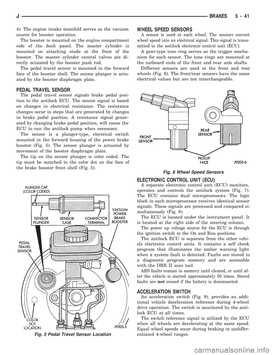
The pedal travel sensor is mounted in the forward
face of the booster shell. The sensor plunger is actu-
ated by the booster diaphragm plate.
PEDAL TRAVEL SENSOR
The pedal travel sensor signals brake pedal posi-
tion to the antilock ECU. The sensor signal is based
on changes in electrical resistance. The resistance
changes occur in steps that are generated by changes
in brake pedal position. A resistance signal gener-
ated by changing brake pedal position, will cause the
ECU to run the antilock pump when necessary.
The sensor is a plunger-type, electrical switch
mounted in the forward housing of the power brake
booster (Fig. 5). The sensor plunger is actuated by
movement of the booster diaphragm plate.
The tip on the sensor plunger is color coded. The
tip must be matched to the color dot on the face of
the brake booster front shell (Fig. 5).
WHEEL SPEED SENSORS
A sensor is used at each wheel. The sensors convert
wheel speed into an electrical signal. This signal is trans-
mitted to the antilock electronic control unit (ECU).
A gear-type tone ring serves as the trigger mecha-
nism for each sensor. The tone rings are mounted at
the outboard ends of the front and rear axle shafts.
Different sensors are used at the front and rear
wheels (Fig. 6). The front/rear sensors have the same
electrical values but are not interchangeable.
ELECTRONIC CONTROL UNIT (ECU)
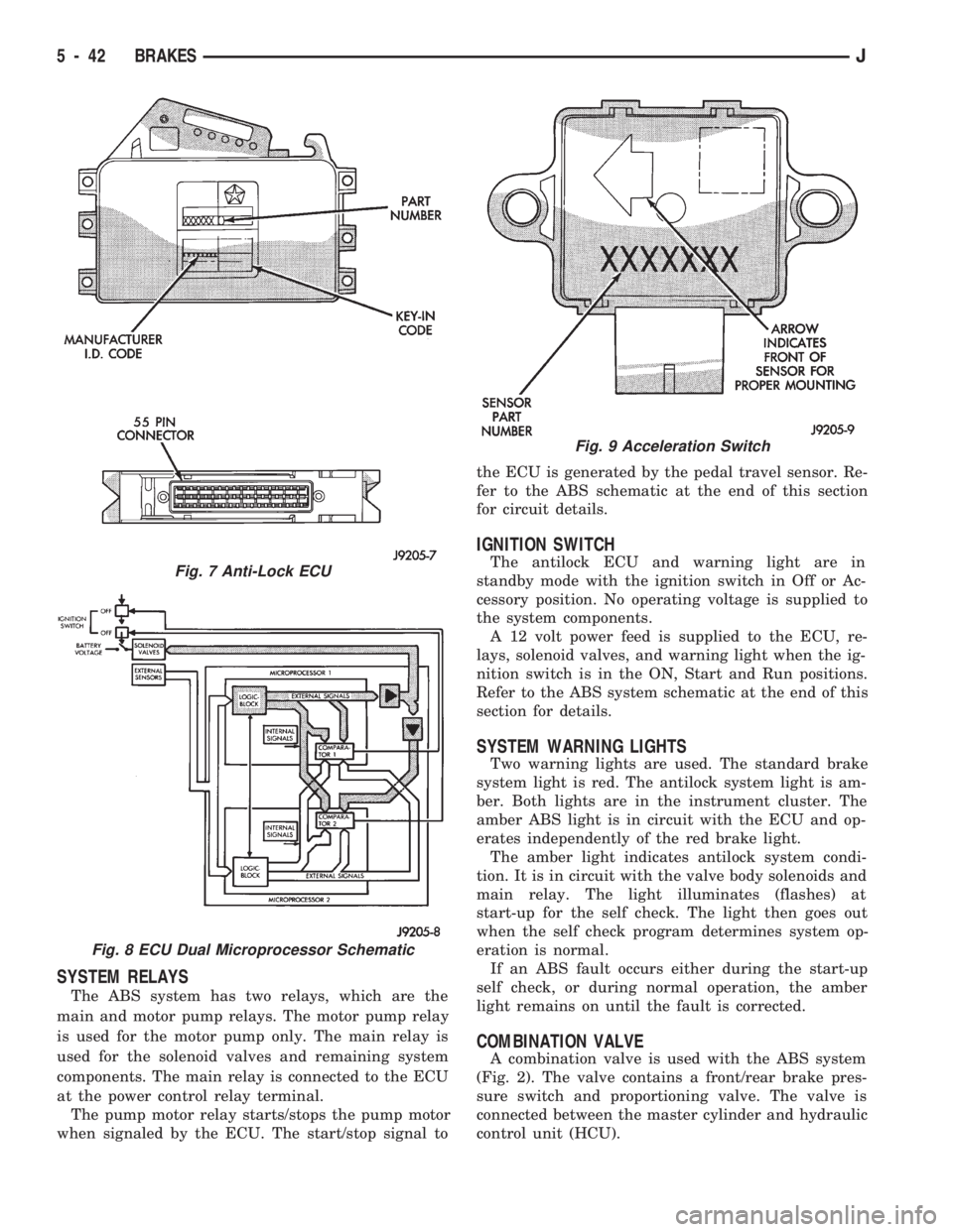
A separate electronic control unit (ECU) monitors,
operates and controls the antilock system (Fig. 7).
The ECU contains dual microprocessors. The logic
block in each microprocessor receives identical sensor
signals. These signals are processed and compared si-
multaneously (Fig. 8).
The ECU is located under the instrument panel. It
is located at the right side of the steering column.
The power up voltage source for the ECU is through
the ignition switch in the On and Run positions.
The antilock ECU is separate from the other vehi-
cle electronic control units. It contains a self check
program that illuminates the amber warning light
when a system fault is detected. Faults are stored in
a diagnostic program memory and are accessible
with the DRB II scan tool.
ABS faults remain in memory until cleared, or until af-
ter the vehicle is started approximately 50 times. Stored
faults arenoterased if the battery is disconnected.
ACCELERATION SWITCH
An acceleration switch (Fig. 9), provides an addi-
tional vehicle deceleration reference during 4-wheel
drive operation. The switch is monitored by the anti-
lock ECU at all times.
The switch reference signal is utilized by the ECU
when all wheels are decelerating at the same speed.
Equal wheel speeds occur during braking in undiffer-
entiated 4-wheel ranges.
Fig. 5 Pedal Travel Sensor Location
Fig. 6 Wheel Speed Sensors
JBRAKES 5 - 41
Page 189 of 1784
SYSTEM RELAYS
The ABS system has two relays, which are the
main and motor pump relays. The motor pump relay
is used for the motor pump only. The main relay is
used for the solenoid valves and remaining system
components. The main relay is connected to the ECU
at the power control relay terminal.
The pump motor relay starts/stops the pump motor
when signaled by the ECU. The start/stop signal tothe ECU is generated by the pedal travel sensor. Re-
fer to the ABS schematic at the end of this section
for circuit details.
IGNITION SWITCH
The antilock ECU and warning light are in
standby mode with the ignition switch in Off or Ac-
cessory position. No operating voltage is supplied to
the system components.
A 12 volt power feed is supplied to the ECU, re-
lays, solenoid valves, and warning light when the ig-
nition switch is in the ON, Start and Run positions.
Refer to the ABS system schematic at the end of this
section for details.
SYSTEM WARNING LIGHTS
Two warning lights are used. The standard brake
system light is red. The antilock system light is am-
ber. Both lights are in the instrument cluster. The
amber ABS light is in circuit with the ECU and op-
erates independently of the red brake light.
The amber light indicates antilock system condi-
tion. It is in circuit with the valve body solenoids and
main relay. The light illuminates (flashes) at
start-up for the self check. The light then goes out
when the self check program determines system op-
eration is normal.
If an ABS fault occurs either during the start-up
self check, or during normal operation, the amber
light remains on until the fault is corrected.
COMBINATION VALVE
A combination valve is used with the ABS system
(Fig. 2). The valve contains a front/rear brake pres-
sure switch and proportioning valve. The valve is
connected between the master cylinder and hydraulic
control unit (HCU).
Fig. 7 Anti-Lock ECU
Fig. 8 ECU Dual Microprocessor Schematic
Fig. 9 Acceleration Switch
5 - 42 BRAKESJ
Page 190 of 1784
ANTILOCK BRAKE SYSTEM OPERATION
INDEX
page page
ABS Operation in Antilock Braking Mode....... 43
ABS Operation in Normal Braking Mode....... 43
Acceleration Switch Operation............... 45
ECY Operation.......................... 46HCU Pump and Pedal Travel Sensor Operation . 44
HCU Solenoid Valve Operation.............. 43
System Power-Up and Initialization........... 43
Wheel Speed Sensor Operation............. 45
SYSTEM POWER-UP AND INITIALIZATION
The antilock system is in standby mode with the
ignition switch in Off or Accessory position. The an-
tilock electrical components are not operational.
Turning the ignition switch to On or Run position
allows battery voltage to flow through the switch to
the ECU ignition terminal.
The ABS system is activated when battery voltage
is supplied to the ECU. The ECU performs a system
initialization procedure at this point. Initialization
consists of a static and dynamic self check of system
electrical components.
The static check occurs immediately after the igni-
tion switch is turned to the On position. The dynamic
check occurs when vehicle road speed reaches ap-
proximately 10 kph (6 mph). During the dynamic
check, the ECU briefly cycles the pump to verify op-
eration. The HCU solenoids are checked continu-
ously.
If an ABS component exhibits a fault during ini-
tialization, the ECU illuminates the amber warning
light and registers a fault code in the microprocessor
memory.
ABS OPERATION IN NORMAL BRAKING MODE
The ECU monitors wheel speed sensor inputs con-
tinuously while the vehicle is in motion. However,
the ECU will not activate any ABS components as
long as sensor inputs and the acceleration switch in-
dicate normal braking.
During normal braking, the master cylinder, power
booster and wheel brake units all function as they
would in a vehicle without ABS. The HCU compo-
nents are not activated.
ABS OPERATION IN ANTILOCK BRAKING MODE
The purpose of the antilock system is to prevent
wheel lockup during periods of high wheel slip. Pre-
venting lockup helps maintain vehicle braking action
and steering control.
The antilock ECU activates the system whenever
sensor signals indicate periods of high wheel slip.
High wheel slip can be described as the point where
wheel rotation begins approaching zero (or lockup)
during braking. Periods of high wheel slip occur
when brake stops involve high pedal pressure and
rate of vehicle deceleration.The antilock system retards lockup during high
slip conditions by modulating fluid apply pressure to
the wheel brake units.
Brake fluid apply pressure is modulated according
to wheel speed, degree of slip and rate of decelera-
tion. A sensor at each wheel converts wheel speed
into electrical signals. These signals are transmitted
to the ECU for processing and determination of
wheel slip and deceleration rate.
The Jeep ABS system has three fluid pressure con-
trol channels. The front brakes are controlled sepa-
rately and the rear brakes in tandem (Fig. 10). A
speed sensor input signal indicating high slip condi-
tions activates the ECU antilock program.
Two solenoid valves are used in each antilock con-
trol channel (Fig. 11). The valves are all located
within the HCU valve body and work in pairs to ei-
ther increase, hold, or decrease apply pressure as
needed in the individual control channels.
The solenoid valves are not static during antilock
braking. They are cycled continuously to modulate
pressure. Solenoid cycle time in antilock mode can be
measured in milliseconds.
HCU SOLENOID VALVE OPERATION
Normal Braking
During normal braking, the HCU solenoid valves
and pump are not activated. The master cylinder and
power booster operate the same as a vehicle without
an ABS brake system.
Antilock Pressure Modulation
Solenoid valve pressure modulation occurs in three
stages which are: pressure increase, pressure hold,
and pressure decrease. The valves are all contained
in the valve body portion of the HCU.
Pressure Decrease
The outlet valve is opened and the inlet valve is
closed during the pressure decrease cycle (Fig. 11).
A pressure decrease cycle is initiated when speed
sensor signals indicate high wheel slip at one or
more wheels. At this point, the ECU opens the outlet
valve. Opening the outlet valve also opens the hy-
draulic return circuit to the master cylinder reser-
JANTILOCK BRAKE SYSTEM OPERATION 5 - 43
Page 200 of 1784
ECU REPLACEMENTÐXJ
ECU Removal
(1) Turn ignition key to Off position.
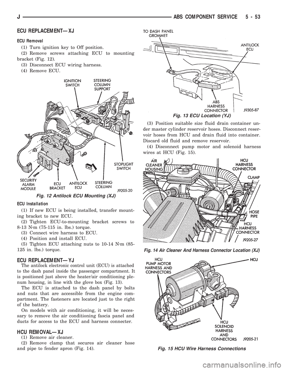
(2) Remove screws attaching ECU to mounting
bracket (Fig. 12).
(3) Disconnect ECU wiring harness.
(4) Remove ECU.
ECU Installation
(1) If new ECU is being installed, transfer mount-
ing bracket to new ECU.
(2) Tighten ECU-to-mounting bracket screws to
8-13 Nzm (75-115 in. lbs.) torque.
(3) Connect wire harness to ECU.
(4) Position and install ECU.
(5) Tighten ECU attaching nuts to 10-14 Nzm (85-
125 in. lbs.) torque.
ECU REPLACEMENTÐYJ
The antilock electronic control unit (ECU) is attached
to the dash panel inside the passenger compartment. It
is positioned just above the heater/air conditioning ple-
num housing, in line with the glove box (Fig. 13).
The ECU is attached to the dash panel by bolts
and nuts that are accessible from the engine com-
partment. The fasteners are located just to the right
of the battery.
On models with air conditioning, it will be neces-
sary to remove the air conditioning fascia panel and
ducts for access to the ECU and harness connecter.
HCU REMOVALÐXJ
(1) Remove air cleaner.
(2) Remove clamp that secures air cleaner hose
and pipe to fender apron (Fig. 14).(3) Position suitable size fluid drain container un-
der master cylinder reservoir hoses. Disconnect reser-
voir hoses from HCU and drain fluid into container.
Discard old fluid and remove reservoir.
(4) Disconnect pump motor and solenoid harness
wires at HCU (Fig. 15).
Fig. 12 Antilock ECU Mounting (XJ)
Fig. 13 ECU Location (YJ)
Fig. 14 Air Cleaner And Harness Connector Location (XJ)
Fig. 15 HCU Wire Harness Connections
JABS COMPONENT SERVICE 5 - 53