1994 JEEP CHEROKEE seat adjustment
[x] Cancel search: seat adjustmentPage 213 of 1784
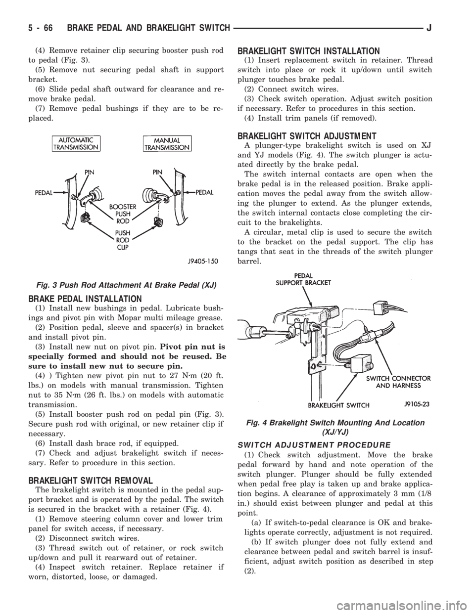
(4) Remove retainer clip securing booster push rod
to pedal (Fig. 3).
(5) Remove nut securing pedal shaft in support
bracket.
(6) Slide pedal shaft outward for clearance and re-
move brake pedal.
(7) Remove pedal bushings if they are to be re-
placed.
BRAKE PEDAL INSTALLATION
(1) Install new bushings in pedal. Lubricate bush-
ings and pivot pin with Mopar multi mileage grease.
(2) Position pedal, sleeve and spacer(s) in bracket
and install pivot pin.
(3) Install new nut on pivot pin.Pivot pin nut is
specially formed and should not be reused. Be
sure to install new nut to secure pin.
(4) ) Tighten new pivot pin nut to 27 Nzm (20 ft.
lbs.) on models with manual transmission. Tighten
nut to 35 Nzm (26 ft. lbs.) on models with automatic
transmission.
(5) Install booster push rod on pedal pin (Fig. 3).
Secure push rod with original, or new retainer clip if
necessary.
(6) Install dash brace rod, if equipped.
(7) Check and adjust brakelight switch if neces-
sary. Refer to procedure in this section.
BRAKELIGHT SWITCH REMOVAL
The brakelight switch is mounted in the pedal sup-
port bracket and is operated by the pedal. The switch
is secured in the bracket with a retainer (Fig. 4).
(1) Remove steering column cover and lower trim
panel for switch access, if necessary.
(2) Disconnect switch wires.
(3) Thread switch out of retainer, or rock switch
up/down and pull it rearward out of retainer.
(4) Inspect switch retainer. Replace retainer if
worn, distorted, loose, or damaged.
BRAKELIGHT SWITCH INSTALLATION
(1) Insert replacement switch in retainer. Thread
switch into place or rock it up/down until switch
plunger touches brake pedal.
(2) Connect switch wires.
(3) Check switch operation. Adjust switch position
if necessary. Refer to procedures in this section.
(4) Install trim panels (if removed).
BRAKELIGHT SWITCH ADJUSTMENT
A plunger-type brakelight switch is used on XJ
and YJ models (Fig. 4). The switch plunger is actu-
ated directly by the brake pedal.
The switch internal contacts are open when the
brake pedal is in the released position. Brake appli-
cation moves the pedal away from the switch allow-
ing the plunger to extend. As the plunger extends,
the switch internal contacts close completing the cir-
cuit to the brakelights.
A circular, metal clip is used to secure the switch
to the bracket on the pedal support. The clip has
tangs that seat in the threads of the switch plunger
barrel.
SWITCH ADJUSTMENT PROCEDURE
(1) Check switch adjustment. Move the brake
pedal forward by hand and note operation of the
switch plunger. Plunger should be fully extended
when pedal free play is taken up and brake applica-
tion begins. A clearance of approximately 3 mm (1/8
in.) should exist between plunger and pedal at this
point.
(a) If switch-to-pedal clearance is OK and brake-
lights operate correctly, adjustment is not required.
(b) If switch plunger does not fully extend and
clearance between pedal and switch barrel is insuf-
ficient, adjust switch position as described in step
(2).
Fig. 3 Push Rod Attachment At Brake Pedal (XJ)
Fig. 4 Brakelight Switch Mounting And Location
(XJ/YJ)
5 - 66 BRAKE PEDAL AND BRAKELIGHT SWITCHJ
Page 306 of 1784

OVERHEAD CONSOLE
CONTENTS
page page
COMPASS REPAIR PROCEDURES.......... 4
CONSOLE REPAIR PROCEDURES........... 6
DESCRIPTION........................... 1DIAGNOSTIC PROCEDURES............... 1
THERMOMETER AND SENSOR SYSTEM REPAIR
PROCEDURES......................... 6
DESCRIPTION
The overhead console includes:
²a compass/temperature display
²reading and courtesy lights for the front and rear
seats
²the receiver for the keyless entry system
²storage compartment for remote garage door
opener
²storage compartment for sunglasses.
COMPASS
The compass will display the direction the vehicle
is pointed, using the eight major compass headings
(Examples: North is ``N'', Northeast is ``NE''). It does
not display the headings in actual degrees. The dis-
play is turned on/off using the TEMP/COMP button
on the left of the display.
The compass is a self calibrating unit that should
not require recalibration. The only calibration that
may prove necessary is to drive the vehicle in 3 com-
plete circles, on level ground, in not less than 48 sec-
onds. This will ``reorient'' the unit to its vehicle. The
unit also will compensate for magnetism the vehicle
may acquire during its life. Care should be used to
avoid putting anything magnetic on the roof of the
vehicle.
The unit can compensate for some magnetic fields
in the body. The use of magnetic attachments like
antenna mounts or repair order ``hats'' placed di-
rectly on the roof can exceed the compensation abil-
ity of the unit. Magnetic bit drivers used on the
fasteners to hold the assembly to the roof header can
also affect operation. If the vehicle roof should be-
come magnetized, then the degaussing and calibra-
tion procedures may be required to restore proper
operation.
If the compass functions but accuracy is suspect, it
may be necessary to perform a variation adjustment.
This procedure allows the unit to accommodate vari-
ations in the earth's magnetic field strength based on
geographic location.
If the compass has blanked out and only CAL
appears, degaussing may be necessary to re-
move residual magnetic fields.
THERMOMETER
The ambient temperature display can be changed
from Fahrenheit to Celsius using the U.S./METRIC
button on the right of the display. The temperature
reported is not an instant reading of conditions but
an average temperature. It may take the unit several
minutes to react to a major change such as driving
out of a heated garage into winter temperatures.
When the ignition switch is turned OFF, the last
displayed temperature reading stays in memory.
When the ignition switch is turned ON again the
thermometer will display the memory temperature
for one minute; then update the display to the actual
temperature within five minutes.
READING AND COURTESY LAMPS
All reading and courtesy lamps in the overhead
console are activated by the door courtesy circuit.
When all four doors and the liftgate are closed the
lamps can be activated by depressing the correspond-
ing lens. When any door or the liftgate is open, the
switches are disabled. They will not turn the lamps
off.
MAP AND COURTESY LAMPS
These lamps offer several unique features. Both the
map and courtesy lamps can be turned on with the
integral ``Soft Touch'' switch. Pushing this switch en-
ergizes an electrical circuit, which in turn directs
power to the light. The map lamps are unaffected by
the door switches, while the courtesy lamps are
turned on with the opening of any door. When any
door is open, the ``Soft Touch'' switches are disabled,
you cannot turn the lights off with these switches.
DIAGNOSTIC PROCEDURES
Follow the appropriate diagnostic flow chart:
²Chart 1 describes the procedures for compass and
display problems.
²Chart 2 describes the procedures for illumination
lamp problems.
²Chart 3 describes the procedures for outside tem-
perature measuring problems.
JOVERHEAD CONSOLE 8C - 1
Page 843 of 1784

can easily be wiped off. Components should be
torqued in place within 15 minutes. The use of a lo-
cating dowel is recommended during assembly to pre-
vent smearing the material off location.
ENGINE PERFORMANCE
To provide best vehicle performance and lowest ve-
hicle emissions, it is most important that the tune-up
be done accurately. Use the specifications listed on
the Vehicle Emission Control Information label
found on the engine compartment hood.
(1) Test battery specific gravity. Add water, if nec-
essary. Clean and tighten battery connections.
(2) Test cranking amperage draw (refer to Group
8B, Battery/Starter Service for the proper proce-
dures).
(3) Tighten the intake manifold bolts (refer to
Group 11, Exhaust System and Intake Manifold for
the proper specifications).
(4) Perform cylinder compression test:
(a) Check engine oil level and add oil, if neces-
sary.
(b) Drive the vehicle until engine reaches normal
operating temperature.
(c) Select a route free from traffic and other
forms of congestion, observe all traffic laws and
briskly accelerate through the gears several times.
The higher engine speed may help clean out valve
seat deposits which can prevent accurate compres-
sion readings.
CAUTION: DO NOT overspeed the engine.
(d) Remove all spark plugs from engine. As
spark plugs are being removed, check electrodes for
abnormal firing indicators - fouled, hot, oily, etc.
Record cylinder number of spark plug for future
reference.
(e) Disconnect coil wire from distributor and se-
cure to good ground to prevent a spark from start-
ing a fire.
(f) Be sure throttle blades are fully open during
the compression check.
(g) Insert compression gage adaptor into the
No.1 spark plug hole. Crank engine until maxi-
mum pressure is reached on gauge. Record this
pressure as No.1 cylinder pressure.
(h) Repeat Step 4g for all remaining cylinders.
(i) Compression should not be less than 689 kPa
(100 psi) and not vary more than 172 kPa (25 psi)
from cylinder to cylinder.
(j) If cylinder(s) have abnormally low compres-
sion pressures, repeat steps 4a through 4h.
(k) If the same cylinder(s) repeat an abnormally
low reading, it could indicate the existence of a
problem in the cylinder.
The recommended compression pressures are
to be used only as a guide to diagnosing engineproblems. An engine should NOT be disassem-
bled to determine the cause of low compression
unless some malfunction is present.
(5) Clean or replace spark plugs as necessary. Ad-
just gap (refer to Group 8D, Ignition System for gap
adjustment and torque).
(6) Test resistance of spark plug cables (refer to
Group 8D, Ignition System).
(7) Inspect the primary wire. Test coil output volt-
age, primary and secondary resistance. Replace parts
as necessary (refer to Group 8D, Ignition System and
make necessary adjustment).
(8) Set ignition timing to specifications (refer to
Specification Label on engine compartment hood).
(9) Perform a combustion analysis.
(10) Test fuel pump for pressure and vacuum (refer
to Group 14, Fuel System for the proper specifica-
tions).
(11) Inspect air filter element (refer to Group 0,
Lubrication and Maintenance for the proper proce-
dure).
(12) Inspect crankcase ventilation system (refer to
Group 0, Lubrication and Maintenance for the proper
procedure).
(13) For emission controls refer to Group 25, Emis-
sion Controls System for service procedures.
(14) Inspect and adjust accessory belt drives (refer
to Group 7, Cooling System for the proper adjust-
ments).
(15) Road test vehicle as a final test.
HONING CYLINDER BORES
Before honing, stuff plenty of clean shop towels un-
der the bores and over the crankshaft to keep abra-
sive materials from entering the crankshaft area.
(1) Used carefully, the Cylinder Bore Sizing Hone
C-823 equipped with 220 grit stones, is the best tool
for this job. In addition to deglazing, it will reduce
taper and out-of-round as well as removing light
scuffing, scoring or scratches. Usually a few strokes
will clean up a bore and maintain the required lim-
its.
CAUTION: DO NOT use rigid type hones to remove
cylinder wall glaze.
(2) Deglazing of the cylinder walls may be done if
the cylinder bore is straight and round. Use a cylin-
der surfacing hone, Honing Tool C-3501, equipped
with 280 grit stones (C-3501-3810). 20-60 strokes, de-
pending on the bore condition, will be sufficient to
provide a satisfactory surface. Using honing oil
C-3501-3880 or a light honing oil available from ma-
jor oil distributors.
CAUTION: DO NOT use engine or transmission oil,
mineral spirits or kerosene.
9 - 2 ENGINESJ
Page 1063 of 1784
PITMAN SHAFT AND SIDE COVER REPLACEMENT
REMOVE
(1) Remove steering gear from vehicle. Refer to
Power Steering Gear Replacement in this section.
(2) Remove pitman arm from steering gear. Refer
to Pitman Arm Removal in the Steering Linkage sec-
tion.
(3) Rotate stub shaft back and forth to drain power
steering fluid.
DISASSEMBLE
²Clean exposed end of pitman shaft and housing.
²Clean pitman shaft spline with a wire brush.
(1) Remove preload adjuster nut.
(2) Rotate stub shaft with socket to center gear.
Remove side cover bolts.
(3) Remove side cover, gasket and pitman shaft as
an assembly.
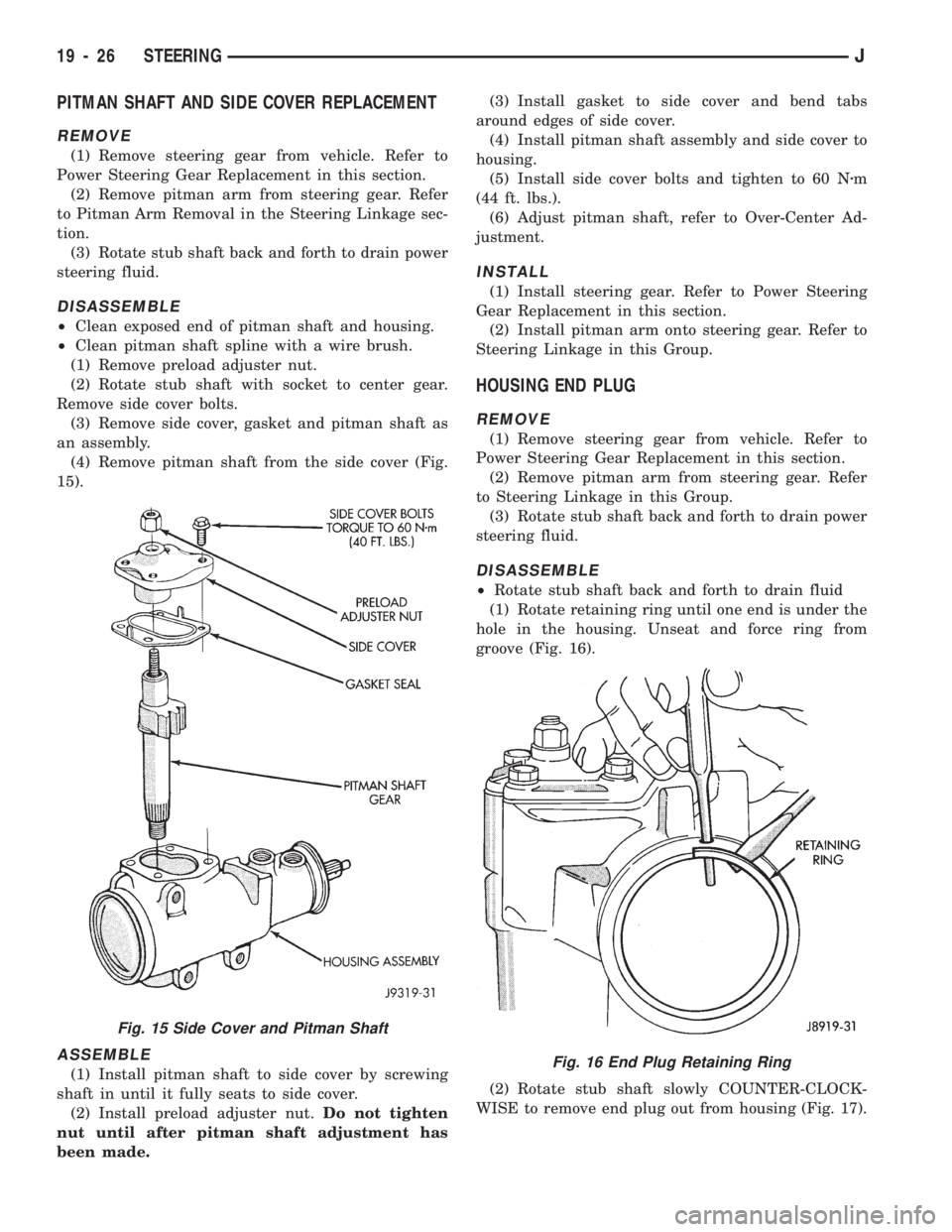
(4) Remove pitman shaft from the side cover (Fig.
15).
ASSEMBLE
(1) Install pitman shaft to side cover by screwing
shaft in until it fully seats to side cover.
(2) Install preload adjuster nut.Do not tighten
nut until after pitman shaft adjustment has
been made.(3) Install gasket to side cover and bend tabs
around edges of side cover.
(4) Install pitman shaft assembly and side cover to
housing.
(5) Install side cover bolts and tighten to 60 Nzm
(44 ft. lbs.).
(6) Adjust pitman shaft, refer to Over-Center Ad-
justment.
INSTALL
(1) Install steering gear. Refer to Power Steering
Gear Replacement in this section.
(2) Install pitman arm onto steering gear. Refer to
Steering Linkage in this Group.
HOUSING END PLUG
REMOVE
(1) Remove steering gear from vehicle. Refer to
Power Steering Gear Replacement in this section.
(2) Remove pitman arm from steering gear. Refer
to Steering Linkage in this Group.
(3) Rotate stub shaft back and forth to drain power
steering fluid.
DISASSEMBLE
²Rotate stub shaft back and forth to drain fluid
(1) Rotate retaining ring until one end is under the
hole in the housing. Unseat and force ring from
groove (Fig. 16).
(2) Rotate stub shaft slowly COUNTER-CLOCK-
WISE to remove end plug out from housing (Fig. 17).
Fig. 16 End Plug Retaining Ring
Fig. 15 Side Cover and Pitman Shaft
19 - 26 STEERINGJ
Page 1064 of 1784
CAUTION: Do not turn stub shaft any farther than
necessary. The recirculating balls will drop out of
the rack piston circuit and fall inside the rack pis-
ton chamber.
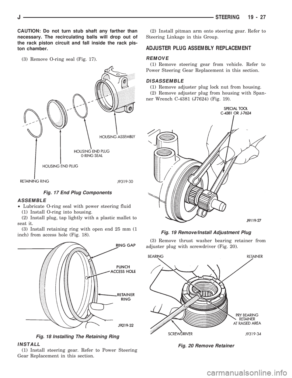
(3) Remove O-ring seal (Fig. 17).
ASSEMBLE
²Lubricate O-ring seal with power steering fluid
(1) Install O-ring into housing.
(2) Install plug, tap lightly with a plastic mallet to
seat it.
(3) Install retaining ring with open end 25 mm (1
inch) from access hole (Fig. 18).
INSTALL
(1) Install steering gear. Refer to Power Steering
Gear Replacement in this section.(2) Install pitman arm onto steering gear. Refer to
Steering Linkage in this Group.
ADJUSTER PLUG ASSEMBLY REPLACEMENT
REMOVE
(1) Remove steering gear from vehicle. Refer to
Power Steering Gear Replacement in this section.
DISASSEMBLE
(1) Remove adjuster plug lock nut from housing.
(2) Remove adjuster plug from housing with Span-
ner Wrench C-4381 (J7624) (Fig. 19).
(3) Remove thrust washer bearing retainer from
adjuster plug with screwdriver (Fig. 20).
Fig. 17 End Plug Components
Fig. 18 Installing The Retaining Ring
Fig. 19 Remove/Install Adjustment Plug
Fig. 20 Remove Retainer
JSTEERING 19 - 27
Page 1069 of 1784
turning the stub shaft COUNTERCLOCKWISE.
²The rack piston will be forced onto the tool and
hold the rack piston balls in place.
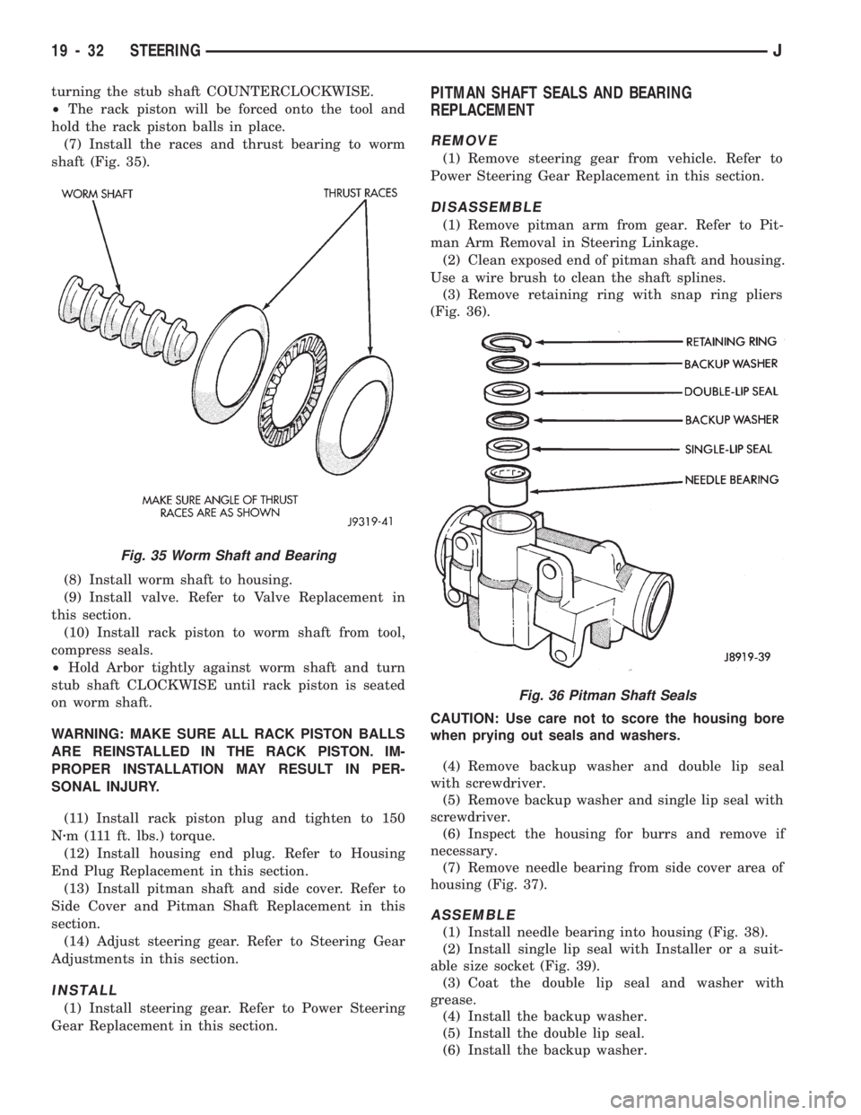
(7) Install the races and thrust bearing to worm
shaft (Fig. 35).
(8) Install worm shaft to housing.
(9) Install valve. Refer to Valve Replacement in
this section.
(10) Install rack piston to worm shaft from tool,
compress seals.
²Hold Arbor tightly against worm shaft and turn
stub shaft CLOCKWISE until rack piston is seated
on worm shaft.
WARNING: MAKE SURE ALL RACK PISTON BALLS
ARE REINSTALLED IN THE RACK PISTON. IM-
PROPER INSTALLATION MAY RESULT IN PER-
SONAL INJURY.
(11) Install rack piston plug and tighten to 150
Nzm (111 ft. lbs.) torque.
(12) Install housing end plug. Refer to Housing
End Plug Replacement in this section.
(13) Install pitman shaft and side cover. Refer to
Side Cover and Pitman Shaft Replacement in this
section.
(14) Adjust steering gear. Refer to Steering Gear
Adjustments in this section.
INSTALL
(1) Install steering gear. Refer to Power Steering
Gear Replacement in this section.
PITMAN SHAFT SEALS AND BEARING
REPLACEMENT
REMOVE
(1) Remove steering gear from vehicle. Refer to
Power Steering Gear Replacement in this section.
DISASSEMBLE
(1) Remove pitman arm from gear. Refer to Pit-
man Arm Removal in Steering Linkage.
(2) Clean exposed end of pitman shaft and housing.
Use a wire brush to clean the shaft splines.
(3) Remove retaining ring with snap ring pliers
(Fig. 36).
CAUTION: Use care not to score the housing bore
when prying out seals and washers.
(4) Remove backup washer and double lip seal
with screwdriver.
(5) Remove backup washer and single lip seal with
screwdriver.
(6) Inspect the housing for burrs and remove if
necessary.
(7) Remove needle bearing from side cover area of
housing (Fig. 37).
ASSEMBLE
(1) Install needle bearing into housing (Fig. 38).
(2) Install single lip seal with Installer or a suit-
able size socket (Fig. 39).
(3) Coat the double lip seal and washer with
grease.
(4) Install the backup washer.
(5) Install the double lip seal.
(6) Install the backup washer.
Fig. 36 Pitman Shaft Seals
Fig. 35 Worm Shaft and Bearing
19 - 32 STEERINGJ
Page 1077 of 1784
(7) Lubricate the wormshaft upper bearing with
chassis lubricant and install it on the wormshaft.
WORMSHAFT BEARING ADJUSTMENT CAP
DISASSEMBLY
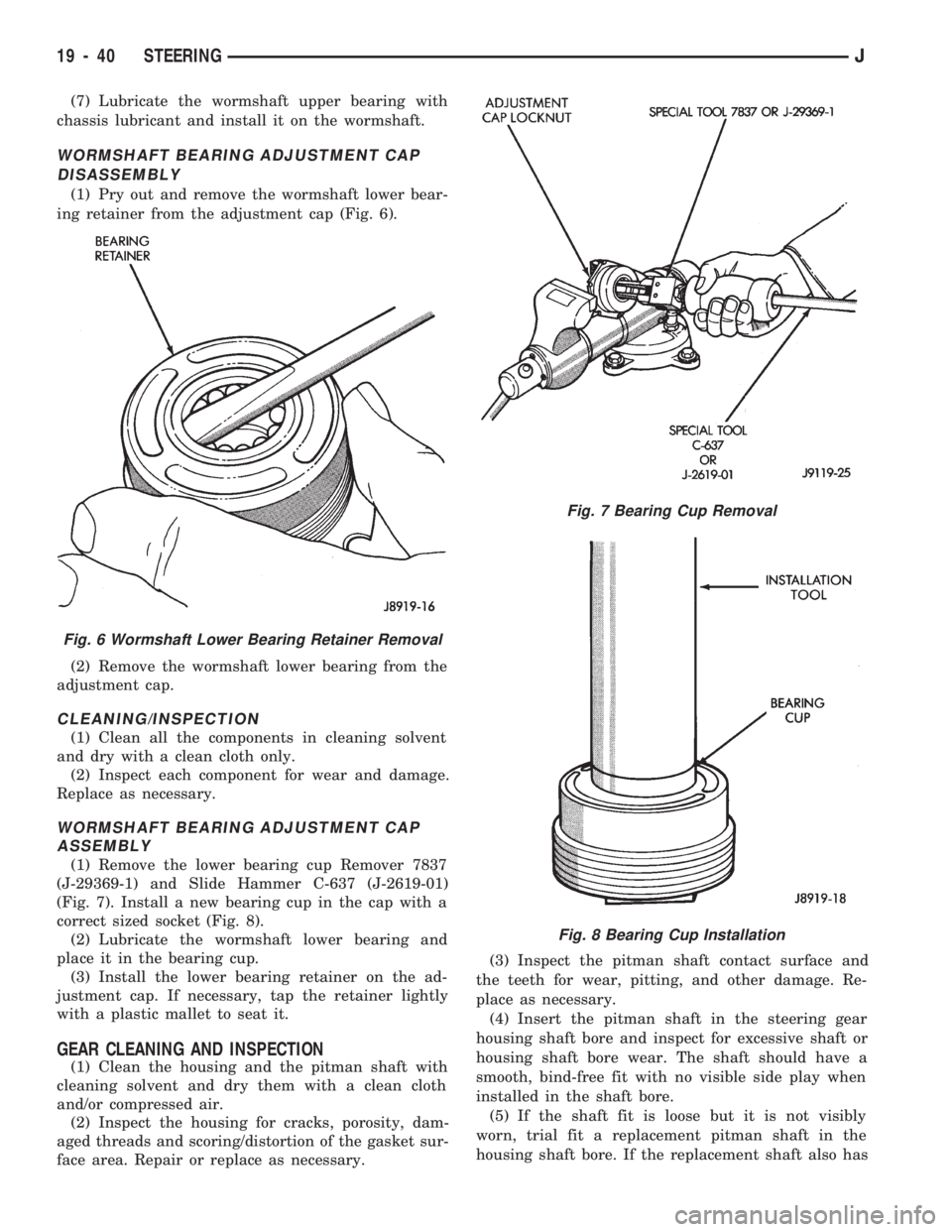
(1) Pry out and remove the wormshaft lower bear-
ing retainer from the adjustment cap (Fig. 6).
(2) Remove the wormshaft lower bearing from the
adjustment cap.
CLEANING/INSPECTION
(1) Clean all the components in cleaning solvent
and dry with a clean cloth only.
(2) Inspect each component for wear and damage.
Replace as necessary.
WORMSHAFT BEARING ADJUSTMENT CAP
ASSEMBLY
(1) Remove the lower bearing cup Remover 7837
(J-29369-1) and Slide Hammer C-637 (J-2619-01)
(Fig. 7). Install a new bearing cup in the cap with a
correct sized socket (Fig. 8).
(2) Lubricate the wormshaft lower bearing and
place it in the bearing cup.
(3) Install the lower bearing retainer on the ad-
justment cap. If necessary, tap the retainer lightly
with a plastic mallet to seat it.
GEAR CLEANING AND INSPECTION
(1) Clean the housing and the pitman shaft with
cleaning solvent and dry them with a clean cloth
and/or compressed air.
(2) Inspect the housing for cracks, porosity, dam-
aged threads and scoring/distortion of the gasket sur-
face area. Repair or replace as necessary.(3) Inspect the pitman shaft contact surface and
the teeth for wear, pitting, and other damage. Re-
place as necessary.
(4) Insert the pitman shaft in the steering gear
housing shaft bore and inspect for excessive shaft or
housing shaft bore wear. The shaft should have a
smooth, bind-free fit with no visible side play when
installed in the shaft bore.
(5) If the shaft fit is loose but it is not visibly
worn, trial fit a replacement pitman shaft in the
housing shaft bore. If the replacement shaft also has
Fig. 6 Wormshaft Lower Bearing Retainer Removal
Fig. 7 Bearing Cup Removal
Fig. 8 Bearing Cup Installation
19 - 40 STEERINGJ
Page 1103 of 1784
(33 in. lbs.) torque. Thread the hazard warning
switch knob into the switch and pull the knob out-
ward.
(38) Install and seat the upper bearing race in the
key/lock cylinder housing.
(39) Install the upper bearing preload spring, the
canceling cam and the lockplate.
(40) Install a replacement lockplate retaining snap
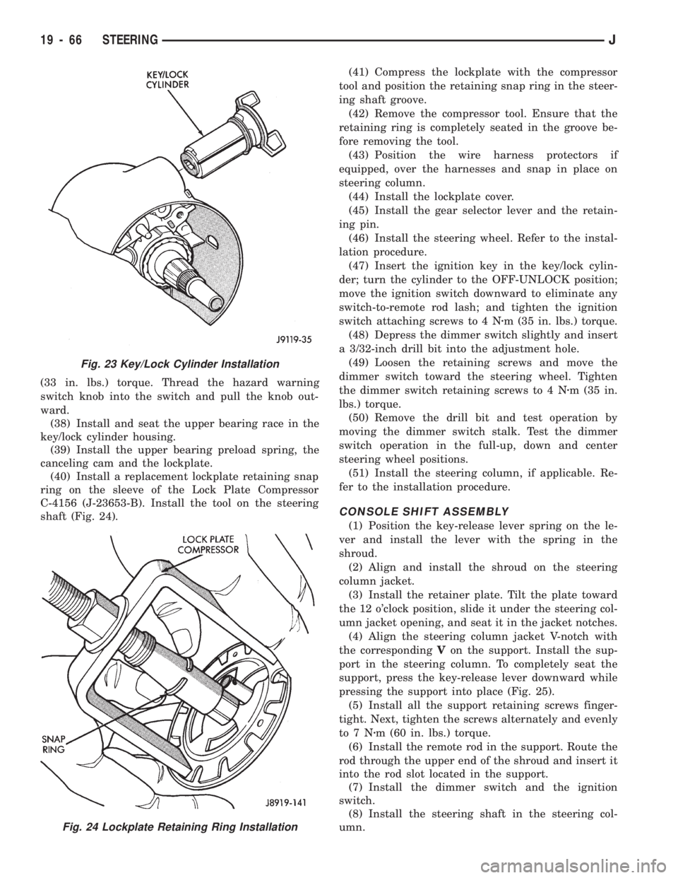
ring on the sleeve of the Lock Plate Compressor
C-4156 (J-23653-B). Install the tool on the steering
shaft (Fig. 24).(41) Compress the lockplate with the compressor
tool and position the retaining snap ring in the steer-
ing shaft groove.
(42) Remove the compressor tool. Ensure that the
retaining ring is completely seated in the groove be-
fore removing the tool.
(43) Position the wire harness protectors if
equipped, over the harnesses and snap in place on
steering column.
(44) Install the lockplate cover.
(45) Install the gear selector lever and the retain-
ing pin.
(46) Install the steering wheel. Refer to the instal-
lation procedure.
(47) Insert the ignition key in the key/lock cylin-
der; turn the cylinder to the OFF-UNLOCK position;
move the ignition switch downward to eliminate any
switch-to-remote rod lash; and tighten the ignition
switch attaching screws to 4 Nzm (35 in. lbs.) torque.
(48) Depress the dimmer switch slightly and insert
a 3/32-inch drill bit into the adjustment hole.
(49) Loosen the retaining screws and move the
dimmer switch toward the steering wheel. Tighten
the dimmer switch retaining screws to 4 Nzm (35 in.
lbs.) torque.
(50) Remove the drill bit and test operation by
moving the dimmer switch stalk. Test the dimmer
switch operation in the full-up, down and center
steering wheel positions.
(51) Install the steering column, if applicable. Re-
fer to the installation procedure.
CONSOLE SHIFT ASSEMBLY
(1) Position the key-release lever spring on the le-
ver and install the lever with the spring in the
shroud.
(2) Align and install the shroud on the steering
column jacket.
(3) Install the retainer plate. Tilt the plate toward
the 12 o'clock position, slide it under the steering col-
umn jacket opening, and seat it in the jacket notches.
(4) Align the steering column jacket V-notch with
the correspondingVon the support. Install the sup-
port in the steering column. To completely seat the
support, press the key-release lever downward while
pressing the support into place (Fig. 25).
(5) Install all the support retaining screws finger-
tight. Next, tighten the screws alternately and evenly
to7Nzm (60 in. lbs.) torque.
(6) Install the remote rod in the support. Route the
rod through the upper end of the shroud and insert it
into the rod slot located in the support.
(7) Install the dimmer switch and the ignition
switch.
(8) Install the steering shaft in the steering col-
umn.
Fig. 23 Key/Lock Cylinder Installation
Fig. 24 Lockplate Retaining Ring Installation
19 - 66 STEERINGJ