1994 JEEP CHEROKEE fuse diagram
[x] Cancel search: fuse diagramPage 429 of 1784
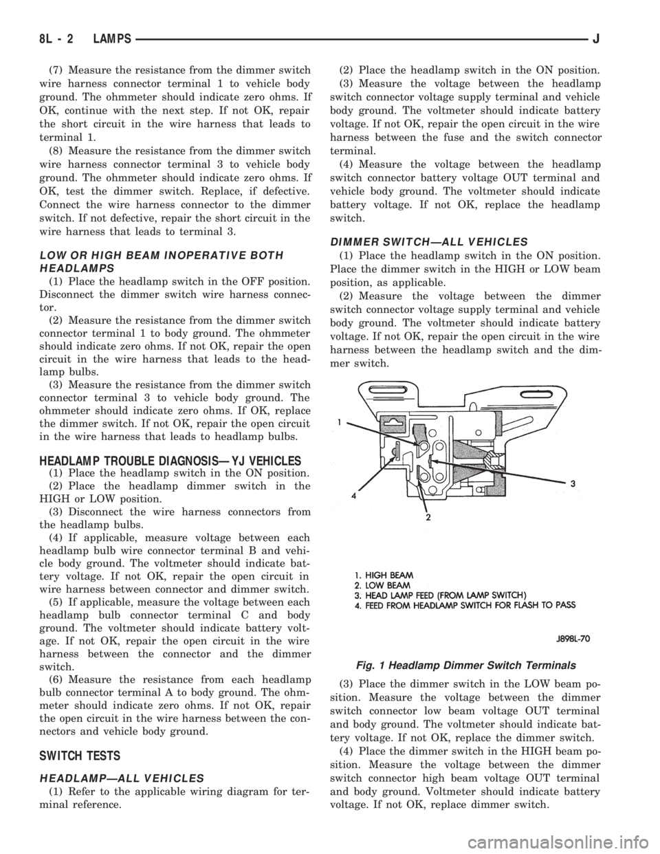
(7) Measure the resistance from the dimmer switch
wire harness connector terminal 1 to vehicle body
ground. The ohmmeter should indicate zero ohms. If
OK, continue with the next step. If not OK, repair
the short circuit in the wire harness that leads to
terminal 1.
(8) Measure the resistance from the dimmer switch
wire harness connector terminal 3 to vehicle body
ground. The ohmmeter should indicate zero ohms. If
OK, test the dimmer switch. Replace, if defective.
Connect the wire harness connector to the dimmer
switch. If not defective, repair the short circuit in the
wire harness that leads to terminal 3.
LOW OR HIGH BEAM INOPERATIVE BOTH
HEADLAMPS
(1) Place the headlamp switch in the OFF position.
Disconnect the dimmer switch wire harness connec-
tor.
(2) Measure the resistance from the dimmer switch
connector terminal 1 to body ground. The ohmmeter
should indicate zero ohms. If not OK, repair the open
circuit in the wire harness that leads to the head-
lamp bulbs.
(3) Measure the resistance from the dimmer switch
connector terminal 3 to vehicle body ground. The
ohmmeter should indicate zero ohms. If OK, replace
the dimmer switch. If not OK, repair the open circuit
in the wire harness that leads to headlamp bulbs.
HEADLAMP TROUBLE DIAGNOSISÐYJ VEHICLES
(1) Place the headlamp switch in the ON position.
(2) Place the headlamp dimmer switch in the
HIGH or LOW position.
(3) Disconnect the wire harness connectors from
the headlamp bulbs.
(4) If applicable, measure voltage between each
headlamp bulb wire connector terminal B and vehi-
cle body ground. The voltmeter should indicate bat-
tery voltage. If not OK, repair the open circuit in
wire harness between connector and dimmer switch.
(5) If applicable, measure the voltage between each
headlamp bulb connector terminal C and body
ground. The voltmeter should indicate battery volt-
age. If not OK, repair the open circuit in the wire
harness between the connector and the dimmer
switch.
(6) Measure the resistance from each headlamp
bulb connector terminal A to body ground. The ohm-
meter should indicate zero ohms. If not OK, repair
the open circuit in the wire harness between the con-
nectors and vehicle body ground.
SWITCH TESTS
HEADLAMPÐALL VEHICLES
(1) Refer to the applicable wiring diagram for ter-
minal reference.(2) Place the headlamp switch in the ON position.
(3) Measure the voltage between the headlamp
switch connector voltage supply terminal and vehicle
body ground. The voltmeter should indicate battery
voltage. If not OK, repair the open circuit in the wire
harness between the fuse and the switch connector
terminal.
(4) Measure the voltage between the headlamp
switch connector battery voltage OUT terminal and
vehicle body ground. The voltmeter should indicate
battery voltage. If not OK, replace the headlamp
switch.
DIMMER SWITCHÐALL VEHICLES
(1) Place the headlamp switch in the ON position.
Place the dimmer switch in the HIGH or LOW beam
position, as applicable.
(2) Measure the voltage between the dimmer
switch connector voltage supply terminal and vehicle
body ground. The voltmeter should indicate battery
voltage. If not OK, repair the open circuit in the wire
harness between the headlamp switch and the dim-
mer switch.
(3) Place the dimmer switch in the LOW beam po-
sition. Measure the voltage between the dimmer
switch connector low beam voltage OUT terminal
and body ground. The voltmeter should indicate bat-
tery voltage. If not OK, replace the dimmer switch.
(4) Place the dimmer switch in the HIGH beam po-
sition. Measure the voltage between the dimmer
switch connector high beam voltage OUT terminal
and body ground. Voltmeter should indicate battery
voltage. If not OK, replace dimmer switch.
Fig. 1 Headlamp Dimmer Switch Terminals
8L - 2 LAMPSJ
Page 453 of 1784
A voltage drop of one-half the full amount, approx-
imately 6 volts, indicates a good grid or closed cir-
cuit.
A voltage drop of 12 volts at the centerline indi-
cates a break in the grid between the positive volt-
meter lead and the ground.
No voltage drop (0 volts) at the centerline indicates
a break in the grid between the centerline and the
voltage source or lead.
The exact location of the break can be pinpointed
by moving positive voltmeter lead to the left or right
along grid. An abrupt change in the voltage reading
will be noticed. The break is at that point in the
grid.
REAR WINDOW DEFOGGER GRID REPAIR
Locate the broken or open grid.
Use the grid repair kit (available as a service part)
by using the following procedure:
(1) Mark the location of the broken or open grid on
the exterior surface of the glass using a suitable
marking pencil.
(2) Lightly rub the area to be repaired (inside the
rear window) using fine steel wool. Clean the area
with alcohol.
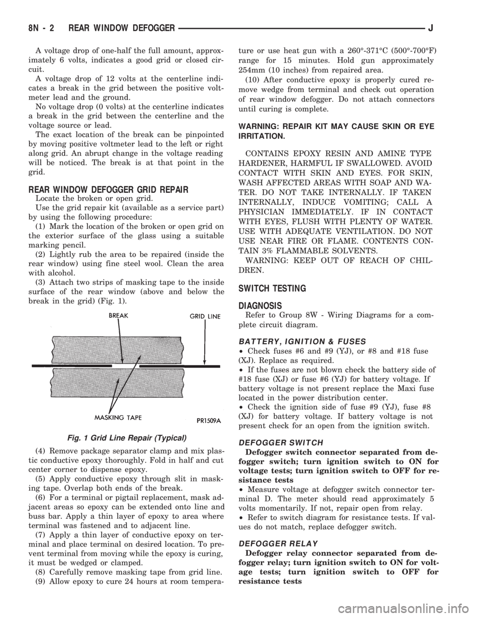
(3) Attach two strips of masking tape to the inside
surface of the rear window (above and below the
break in the grid) (Fig. 1).
(4) Remove package separator clamp and mix plas-
tic conductive epoxy thoroughly. Fold in half and cut
center corner to dispense epoxy.
(5) Apply conductive epoxy through slit in mask-
ing tape. Overlap both ends of the break.
(6) For a terminal or pigtail replacement, mask ad-
jacent areas so epoxy can be extended onto line and
buss bar. Apply a thin layer of epoxy to area where
terminal was fastened and to adjacent line.
(7) Apply a thin layer of conductive epoxy on ter-
minal and place terminal on desired location. To pre-
vent terminal from moving while the epoxy is curing,
it must be wedged or clamped.
(8) Carefully remove masking tape from grid line.
(9) Allow epoxy to cure 24 hours at room tempera-ture or use heat gun with a 260É-371ÉC (500É-700ÉF)
range for 15 minutes. Hold gun approximately
254mm (10 inches) from repaired area.
(10) After conductive epoxy is properly cured re-
move wedge from terminal and check out operation
of rear window defogger. Do not attach connectors
until curing is complete.
WARNING: REPAIR KIT MAY CAUSE SKIN OR EYE
IRRITATION.
CONTAINS EPOXY RESIN AND AMINE TYPE
HARDENER, HARMFUL IF SWALLOWED. AVOID
CONTACT WITH SKIN AND EYES. FOR SKIN,
WASH AFFECTED AREAS WITH SOAP AND WA-
TER. DO NOT TAKE INTERNALLY. IF TAKEN
INTERNALLY, INDUCE VOMITING; CALL A
PHYSICIAN IMMEDIATELY. IF IN CONTACT
WITH EYES, FLUSH WITH PLENTY OF WATER.
USE WITH ADEQUATE VENTILATION. DO NOT
USE NEAR FIRE OR FLAME. CONTENTS CON-
TAIN 3% FLAMMABLE SOLVENTS.
WARNING: KEEP OUT OF REACH OF CHIL-
DREN.
SWITCH TESTING
DIAGNOSIS
Refer to Group 8W - Wiring Diagrams for a com-
plete circuit diagram.
BATTERY, IGNITION & FUSES
²Check fuses #6 and #9 (YJ), or #8 and #18 fuse
(XJ). Replace as required.
²If the fuses are not blown check the battery side of
#18 fuse (XJ) or fuse #6 (YJ) for battery voltage. If
battery voltage is not present replace the Maxi fuse
located in the power distribution center.
²Check the ignition side of fuse #9 (YJ), fuse #8
(XJ) for battery voltage. If battery voltage is not
present check for an open from the ignition switch.
DEFOGGER SWITCH
Defogger switch connector separated from de-
fogger switch; turn ignition switch to ON for
voltage tests; turn ignition switch to OFF for re-
sistance tests
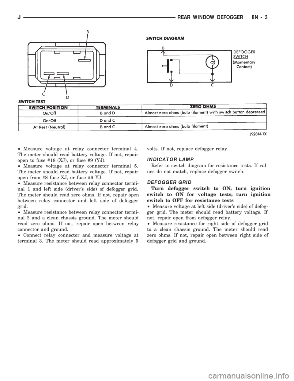
²Measure voltage at defogger switch connector ter-
minal D. The meter should read approximately 5
volts momentarily. If not, repair open from relay.
²Refer to switch diagram for resistance tests. If val-
ues do not match, replace defogger switch.
DEFOGGER RELAY
Defogger relay connector separated from de-
fogger relay; turn ignition switch to ON for volt-
age tests; turn ignition switch to OFF for
resistance tests
Fig. 1 Grid Line Repair (Typical)
8N - 2 REAR WINDOW DEFOGGERJ
Page 454 of 1784
²Measure voltage at relay connector terminal 4.
The meter should read battery voltage. If not, repair
open to fuse #18 (XJ), or fuse #9 (YJ).
²Measure voltage at relay connector terminal 5.
The meter should read battery voltage. If not, repair
open from #8 fuse XJ, or fuse #6 YJ.
²Measure resistance between relay connector termi-
nal 1 and left side (driver's side) of defogger grid.
The meter should read zero ohms. If not, repair open
between relay connector and left side of defogger
grid.
²Measure resistance between relay connector termi-
nal 2 and a clean chassis ground. The meter should
read zero ohms. If not, repair open between relay
connector and ground.
²Connect relay connector and measure voltage at
terminal 3. The meter should read approximately 5volts. If not, replace defogger relay.
INDICATOR LAMP
Refer to switch diagram for resistance tests. If val-
ues do not match, replace defogger switch.
DEFOGGER GRID
Turn defogger switch to ON; turn ignition
switch to ON for voltage tests; turn ignition
switch to OFF for resistance tests
²Measure voltage at left side (driver's side) of defog-
ger grid. The meter should read battery voltage. If
not, repair open from defogger relay.
²Measure resistance for right side of defogger grid
to a clean chassis ground. The meter should read
zero ohms. If not, repair open between right side of
defogger grid and ground.
JREAR WINDOW DEFOGGER 8N - 3
Page 464 of 1784
code received matches the code in the receiver memory
circuit, the receiver triggers the door lock/unlock relays.
The relays complete the circuit to the electric door lock
solenoid to either lock or unlock the doors.
SYSTEM OPERATION
To activate the system, aim the transmitter diode
toward the receiver and press the transmitter signal
button to lock or unlock the doors as desired.
Effective transmitter range is 4.75 meters (15 ft.)
with the transmitter positioned no more than 45 de-
grees from the receiver centerline.
For complete circuit diagrams refer to Group
8W - Wiring Diagrams.
TRANSMITTER PROGRAMMING
Up to 4 Transmitter Identification Codes (TIC's) can
be programed into the receiver at any given time.
(1) Open the driver's door of the vehicle. Leave it
open through the programming procedure.
(2) Move the mechanical door lock lever to the
LOCK position.
(3) Turn the ignition switch to the ON position.
(4) Within 20 seconds, aim a transmitter at the re-
ceiver dome and press the LOCK button for at least
5 seconds. Once the receiver accepts the program-
ming code, the driver's door will unlock.
(5) Once the first transmitter has been pro-
grammed, additional transmitters (up to 4) may be
programmed into the receiver. Within 20 seconds of
the previous transmitter programming, move the me-
chanical door lock lever to the LOCK position. Aimanother transmitter at the receiver dome and press
the LOCK button for at least 5 seconds. The door
lock will cycle again.
(6) To lock the programmed codes into the re-
ceiver, the ignition switch must be turned OFF and
back ON within 20 seconds after programming the
last transmitter's code. At that time, all previous
codes are erased from the module.
DIAGNOSING POWER DOOR LOCKS
NO DOOR LOCKS OPERATE, USING
TRANSMITTER
(1) Measure resistance at keyless entry module
terminal 10. Meter should read zero ohms. If not, re-
pair open to ground.
(2) Measure voltage at keyless entry module termi-
nal 1. Meter should read battery voltage.Battery
voltage must be at least 9 volts for this system to
operate.If not, repair open to #9 fuse.
(3) Jumper test leads keyless entry module termi-
nal 1 to terminal 3. Doors should lock. If OK, replace
module. If not, repair open from terminal 3 to lock
relay terminal 1.
(4) Jumper test leads keyless entry module termi-
nal 1 to terminal 4. Door should unlock. If OK, re-
place module. If not, repair open from terminal 4 to
unlock relay terminal 1.
TRANSMITTER SERVICE
If the receiver malfunctions, only the receiver will
have to be replaced. The new receiver will have to be
reprogrammed. If a transmitter is lost, replace the
transmitter and reprogram the receiver.
Batteries may not be supplied with some re-
placement transmitters. Be sure to check a re-
placement transmitter before attempting to
activate the system.
TRANSMITTER BATTERY REPLACEMENT
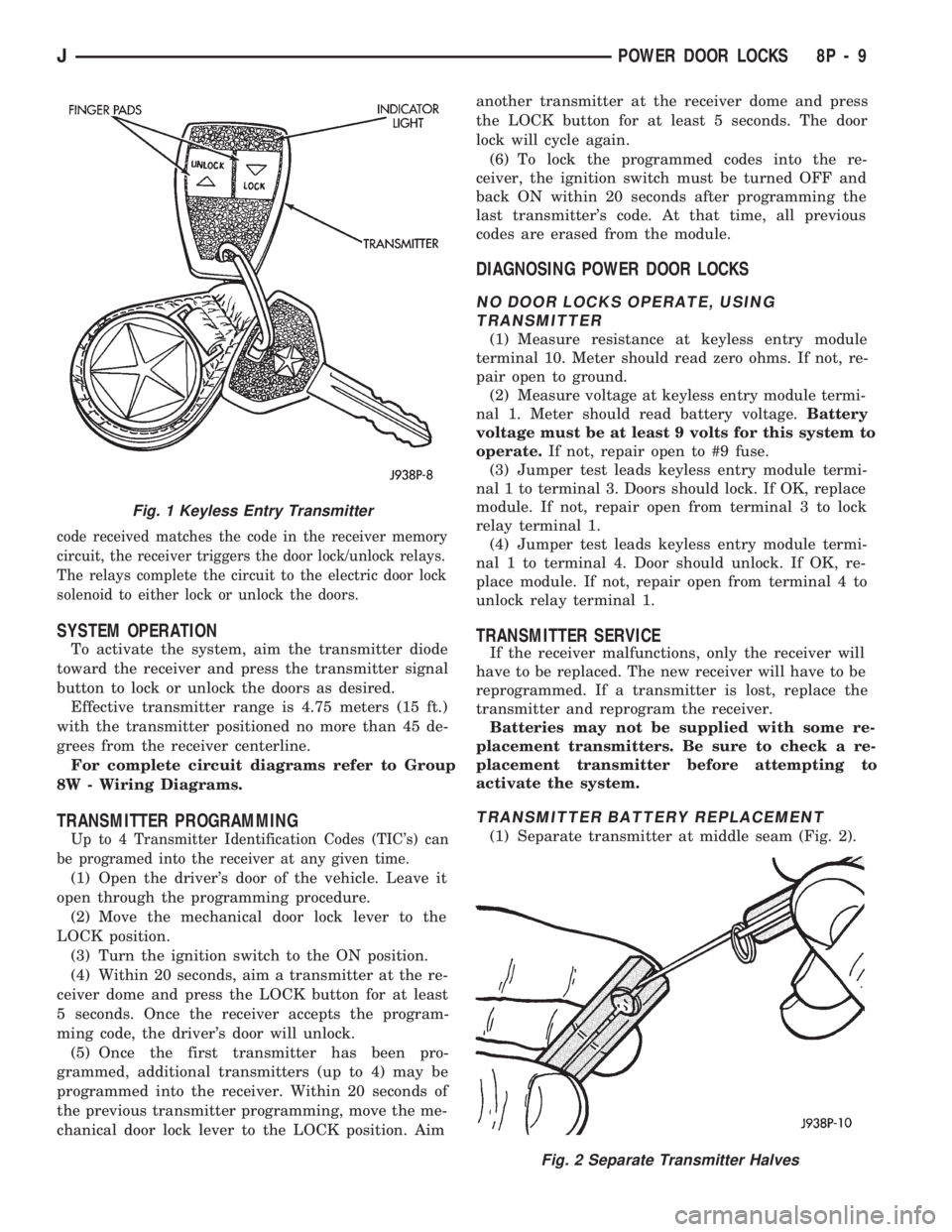
(1) Separate transmitter at middle seam (Fig. 2).
Fig. 2 Separate Transmitter Halves
Fig. 1 Keyless Entry Transmitter
JPOWER DOOR LOCKS 8P - 9
Page 468 of 1784
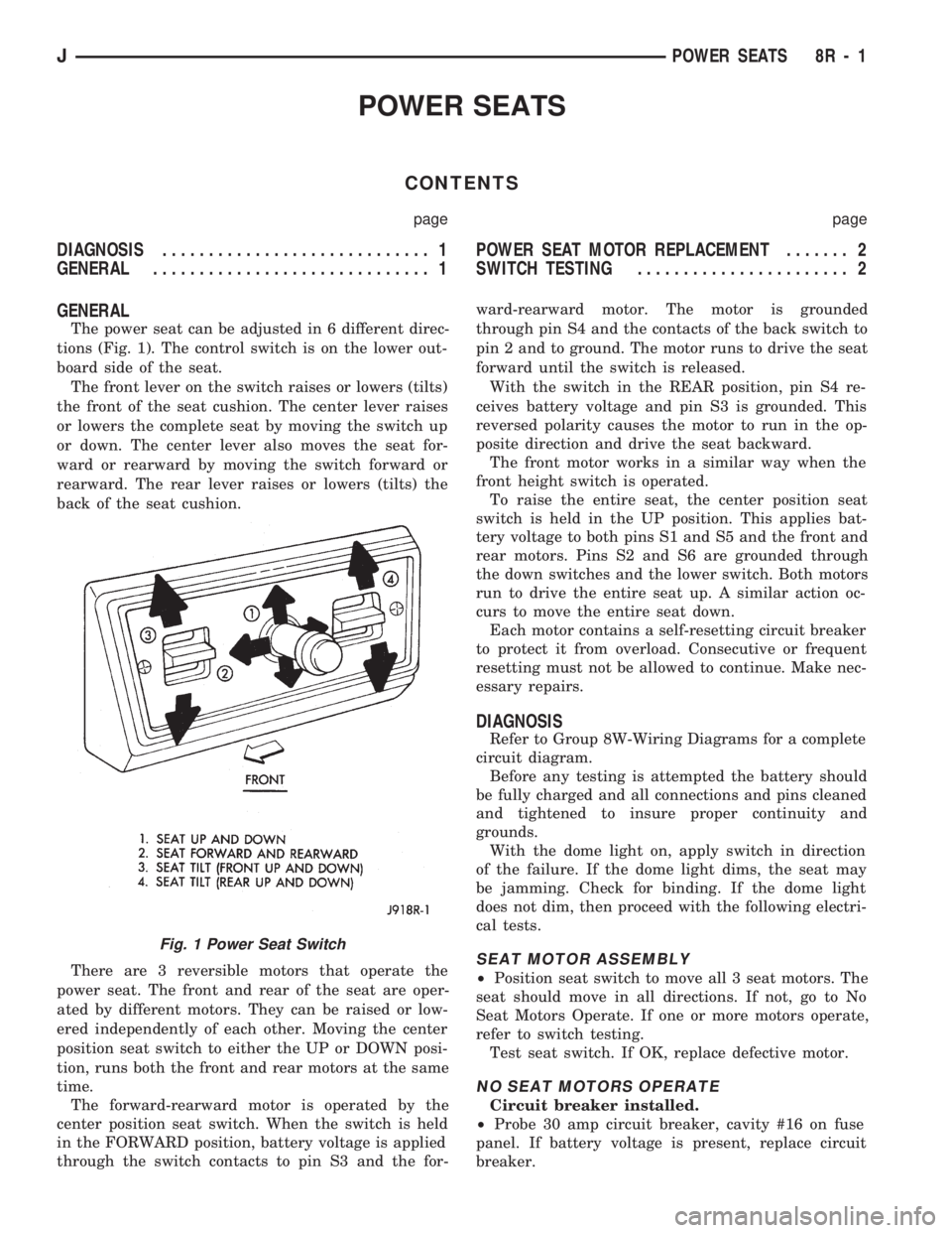
POWER SEATS
CONTENTS
page page
DIAGNOSIS............................. 1
GENERAL.............................. 1POWER SEAT MOTOR REPLACEMENT....... 2
SWITCH TESTING....................... 2
GENERAL
The power seat can be adjusted in 6 different direc-
tions (Fig. 1). The control switch is on the lower out-
board side of the seat.
The front lever on the switch raises or lowers (tilts)
the front of the seat cushion. The center lever raises
or lowers the complete seat by moving the switch up
or down. The center lever also moves the seat for-
ward or rearward by moving the switch forward or
rearward. The rear lever raises or lowers (tilts) the
back of the seat cushion.
There are 3 reversible motors that operate the
power seat. The front and rear of the seat are oper-
ated by different motors. They can be raised or low-
ered independently of each other. Moving the center
position seat switch to either the UP or DOWN posi-
tion, runs both the front and rear motors at the same
time.
The forward-rearward motor is operated by the
center position seat switch. When the switch is held
in the FORWARD position, battery voltage is applied
through the switch contacts to pin S3 and the for-ward-rearward motor. The motor is grounded
through pin S4 and the contacts of the back switch to
pin 2 and to ground. The motor runs to drive the seat
forward until the switch is released.
With the switch in the REAR position, pin S4 re-
ceives battery voltage and pin S3 is grounded. This
reversed polarity causes the motor to run in the op-
posite direction and drive the seat backward.
The front motor works in a similar way when the
front height switch is operated.
To raise the entire seat, the center position seat
switch is held in the UP position. This applies bat-
tery voltage to both pins S1 and S5 and the front and
rear motors. Pins S2 and S6 are grounded through
the down switches and the lower switch. Both motors
run to drive the entire seat up. A similar action oc-
curs to move the entire seat down.
Each motor contains a self-resetting circuit breaker
to protect it from overload. Consecutive or frequent
resetting must not be allowed to continue. Make nec-
essary repairs.
DIAGNOSIS
Refer to Group 8W-Wiring Diagrams for a complete
circuit diagram.
Before any testing is attempted the battery should
be fully charged and all connections and pins cleaned
and tightened to insure proper continuity and
grounds.
With the dome light on, apply switch in direction
of the failure. If the dome light dims, the seat may
be jamming. Check for binding. If the dome light
does not dim, then proceed with the following electri-
cal tests.
SEAT MOTOR ASSEMBLY
²Position seat switch to move all 3 seat motors. The
seat should move in all directions. If not, go to No
Seat Motors Operate. If one or more motors operate,
refer to switch testing.
Test seat switch. If OK, replace defective motor.
NO SEAT MOTORS OPERATE
Circuit breaker installed.
²Probe 30 amp circuit breaker, cavity #16 on fuse
panel. If battery voltage is present, replace circuit
breaker.
Fig. 1 Power Seat Switch
JPOWER SEATS 8R - 1
Page 472 of 1784
POWER WINDOWS
CONTENTS
page page
DESCRIPTION........................... 1
DIAGNOSIS (Figs. 1 and 2)............... 1SWITCH TESTING....................... 5
WINDOW REGULATOR REPLACEMENT...... 9
DESCRIPTION
All XJ vehicles, equipped with power windows,
have a cable driven window regulator system. A per-
manent magnet motor moves each power window.
Each motor raises or lowers the glass when voltage
is supplied to the motor. The direction the motor
turns depends on the polarity of the supply voltage.
The control switches control the supply voltage polar-
ity.
With the ignition switch in the ON position voltage
from the 60 amp fuse in the Power Distribution Cen-
ter is applied through the power window circuit
breaker. Power then goes to the master switch termi-
nal BY and to the passenger's window switches.
When the driver's window switch is moved UP, the
contacts close a current path to:
²terminal DV
²driver's side front window motor
²terminal CV
²the DOWN contact of the driver's side front win-
dow to ground.
The motor then moves the glass up.
Current flows in a similar way when the UP con-
tact in one of the passenger's window switches is
closed. Current flow through the passenger's window
motors must go through the driver's and the passen-
ger's window switches before it reaches ground.
Each motor is protected by a built-in circuit
breaker. If a window switch is held on too long with
the window obstructed or after the window is fully
up or down, the circuit breaker opens the circuit. The
circuit breaker resets automatically as it cools. Do
not allow frequent or consecutive resetting of the cir-
cuit breaker to continue.
DIAGNOSIS (Figs. 1 and 2)
For information concerning wiring or connectors,
refer to Group 8W - Wiring Diagrams.
NO WINDOWS OPERATE
²Measure voltage at power window feed connector
at fuse panel. Meter should read battery voltage. If
not, replace 60 amp fuse in Power Distribution Cen-
ter.
²Turn ignition switch to OFF and measure resis-
tance from side of cigar lighter socket to ground.
Meter should read zero ohms. If not, repair open to
ground.
²Remove master door lock/power window switch as-
sembly mounting screws. Measure resistance at BLK
wire (terminal DX) at driver's side switch. Meter
should read zero ohms. If not, repair open to ground
splice of instrument panel harness.
²Turn ignition switch to ON and measure voltage
at terminal BY at driver's side switch. Meter should
read battery voltage. If not, repair open to circuit
breaker.
²Operate window switch. If the windows move up
and down go to Switch Testing.
²Perform Switch Test Driver's Door. If switch
passes test, replace defective motors.
ONE WINDOW OPERATES
Remove door panel of inoperative window,
probe harness side of unplugged motor connec-
tor.
²Measure voltage at terminal A of connector, hold-
ing switch in the DOWN position. Meter should read
battery voltage. If not, repair open back to master
switch. If additional switch is in circuit (not driver's
side motor), refer to Switch Testing.
²Measure resistance at terminal B of connector,
holding switch in the DOWN position. Meter should
read zero ohms. Caution, maintain DOWN position
while meter lead is attached. If not, repair open back
to master switch. If additional switch is in circuit
(not driver's side motor), refer to Switch Testing. If
both tests are OK, replace regulator.
JPOWER WINDOWS 8S - 1
Page 482 of 1784
POWER MIRRORS
CONTENTS
page page
DIAGNOSIS............................. 1
GENERAL.............................. 1
POWER MIRROR REPLACEMENT........... 4POWER MIRROR SWITCH REPLACEMENT . . . 4
POWER MIRROR SWITCH TESTING......... 2
GENERAL
For information concerning wiring or connectors,
refer to Group 8W - Wiring Diagrams.
The mirror control switch contains two separate
switches, the operating switch and the selector
switch.
Each mirror has two reversible motors: one to ad-
just the mirror view up and down, the other to adjust
the mirror view right and left. The driver operates
three switches that control the polarity of the voltage
to the motors. The mirror select switch directs these
control voltages to either the right or left mirror.
The mirror select switch must be set to L or R to
direct current flow. If the mirror select switch is set
on R and the up-down switch is moved to the UP po-
sition, the voltage path is:
²through the U contact of switch 1
²to pin E
²to the up-down motor in the right mirror.
The ground path is:
²through pin D
²through the mirror select switch contacts
²to the U contacts of switch 3 and switch 2
²to pin F
²to ground.
The right motor runs and tilts the mirror up.
If the switch is pushed to the DOWN position, thesame motor receives voltage. Now the polarity is re-
versed, with pin E grounded. The motor runs in the
opposite direction.
The right mirror left-right motor operates in a sim-
ilar manner when the control switch is moved to the
L or R positions.
The left mirror works the same way as the right
mirror when mirror select switch is moved to L posi-
tion and control switch is operated.
DIAGNOSIS
For information concerning wiring or connectors,
refer to Group 8W - Wiring Diagrams.
²Open door. Dome lamps should light. If not, check
dome fuse.
Remove switch, unplug switch connector
²Measure resistance at mirror switch connector pin
F. Meter should read zero ohms, If not, repair open to
ground.
²Measure voltage at mirror switch connector pin G.
Meter should read battery voltage. If not, repair open
to dome fuse.
Install a jumper lead from pin E to pin F.
²Connect a jumper lead from pin G to: pin A; pin B;
pin C and then pin D. If the mirror moves, replace
switch. If not, repair open to motor and/or replace
motor.
JPOWER MIRRORS 8T - 1
Page 494 of 1784

WIRING DIAGRAMS
CONTENTS
page page
FUSE CHARTS AND RELAY BANKS......... 8
GENERAL INFORMATION.................. 1
SPLICE LOCATIONS..................... 53
WIRING AND COMPONENT IDENTIFICATION . 13WIRING DIAGRAMS XJ.................. 149
WIRING DIAGRAMS XJ RHD............. 271
WIRING DIAGRAMS YJ.................. 73
GENERAL INFORMATION
INDEX
page page
Circuit Identification........................ 2
Component Identification.................... 2
Connector and Terminal Assembly Replacement . . 5
Connector Replacement.................... 4
Connectors.............................. 3
Fusible Link Replacement................... 4
Fusible Links............................. 3
Locating A System........................ 2Secondary Ignition Wiring................... 1
Splice Locations.......................... 2
Symbols, Fuses and Abbreviations............ 6
Terminal Replacement...................... 5
Troubleshooting Wiring Problems.............. 3
Wire Code Identification.................... 2
Wiring Diagram Sheets and Indexes........... 1
Wiring Repair............................ 4
The wiring diagrams contain the latest information
at the time of publication.
Throughout this group references may be made to
a particular vehicle by letter or number designation.
A chart showing the breakdown of these designations
is included in the Introduction Section at the front of
this service manual.
SECONDARY IGNITION WIRING
Secondary ignition wiring is shown in Figures 1
and 2. For additional information on ignition systems
or distributor operation refer to Group 8D Ignition
Systems.
WIRING DIAGRAM SHEETS AND INDEXES
The diagrams are organized to show the basic ve-
hicle and all of its options. Add-on or non-factory op-
tions are not covered. The diagram pages are
identified by a sheet number which is located at the
lower right or left hand corner of each sheet.Page
numbers at the top of each page do not apply to
diagram sheets.
Diagram sheets show all information relating to
the system. This includes feeds, grounds, switch in-
ternal circuity, connectors, splices, and pin identifica-
tion for controllers and modules. All components,switches, and relays are shown in the at rest position
with the key removed from the ignition and the doors
closed.
In certain instances a wire may be referenced to
another sheet. When this happens, the wire will be
identified as to where it is going.
The index used for the diagrams is located at the
beginning of the section. The main system and all re-
lated components are covered.
Fig. 1 Secondary Ignition Wiring 2.5L
JWIRING DIAGRAMS 8W - 1