1994 JEEP CHEROKEE fuel tank removal
[x] Cancel search: fuel tank removalPage 139 of 1784
MULTI-PORT FUEL INJECTION (MFI)ÐCOMPONENT REMOVAL/INSTALLATION
INDEX
page page
Accelerator Pedal and Throttle Cable......... 54
Air Cleaner Housing...................... 54
Air Conditioning (A/C) Clutch Relay........... 54
Air Filter............................... 54
Automatic Shut Down (ASD) Relay........... 54
Brake Switch............................ 54
Camshaft Position Sensor.................. 54
Crankshaft Position Sensor................. 55
Engine Coolant Temperature Sensor.......... 55
Fuel Filter.............................. 55
Fuel Injector............................ 55
Fuel Pump Module....................... 56
Fuel Pump Relay........................ 56
Fuel Rail Assembly....................... 56
Fuel System Pressure Release Procedure...... 56
Fuel Tank Pressure Relief/Rollover Valve...... 56
Fuel Tanks............................. 56Fuel Tubes/Lines/Hoses and Clamps.......... 56
Idle Air Control (IAC) Motor................. 56
Ignition Coil............................. 57
Intake Air Temperature Sensor.............. 54
Intake Manifold.......................... 57
Manifold Absolute Pressure (MAP) Sensor..... 57
Oxygen (O2S) Sensor..................... 57
Park Neutral Switch....................... 58
Power Steering Pressure SwitchÐ2.5L
Engine Only........................... 58
Powertrain Control Module (PCM)............ 58
Quick-Connect Fittings..................... 59
Throttle Body............................ 59
Throttle Position Sensor (TPS).............. 59
Torque Converter Clutch Relay.............. 60
Vehicle Speed Sensor..................... 60
ACCELERATOR PEDAL AND THROTTLE CABLE
Refer to the Accelerator Pedal and Throttle Cable
section of this group for removal/installation proce-
dures.
AIR CONDITIONING (A/C) CLUTCH RELAY
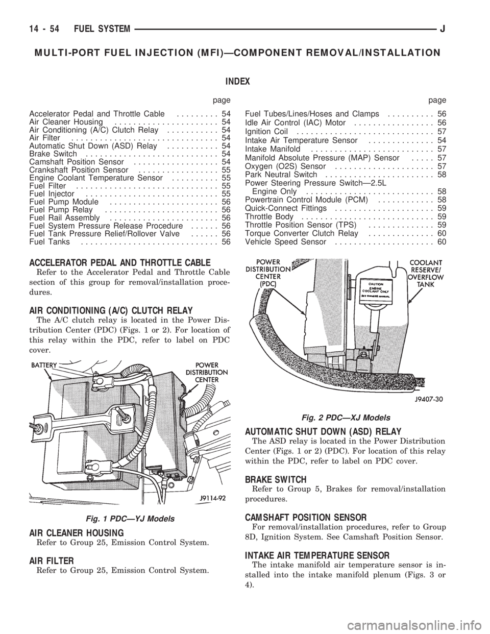
The A/C clutch relay is located in the Power Dis-
tribution Center (PDC) (Figs. 1 or 2). For location of
this relay within the PDC, refer to label on PDC
cover.
AIR CLEANER HOUSING
Refer to Group 25, Emission Control System.
AIR FILTER
Refer to Group 25, Emission Control System.
AUTOMATIC SHUT DOWN (ASD) RELAY
The ASD relay is located in the Power Distribution
Center (Figs. 1 or 2) (PDC). For location of this relay
within the PDC, refer to label on PDC cover.
BRAKE SWITCH
Refer to Group 5, Brakes for removal/installation
procedures.
CAMSHAFT POSITION SENSOR
For removal/installation procedures, refer to Group
8D, Ignition System. See Camshaft Position Sensor.
INTAKE AIR TEMPERATURE SENSOR
The intake manifold air temperature sensor is in-
stalled into the intake manifold plenum (Figs. 3 or
4).
Fig. 1 PDCÐYJ Models
Fig. 2 PDCÐXJ Models
14 - 54 FUEL SYSTEMJ
Page 141 of 1784
INSTALLATION
(1) Install the fuel injector(s) into the fuel rail as-
sembly and install retaining clip(s).
(2) Install fuel rail. Refer to Fuel Rail Installation
in this section.
(3) Start engine and check for fuel leaks.
FUEL PUMP MODULE
Refer to the Fuel Delivery System section of this
group for removal/installation procedures.
FUEL PUMP RELAY
The Fuel Pump relay is located in the Power Dis-
tribution Center (PDC) (Figs. 1 or 2). For location of
this relay within the PDC, refer to label on PDC
cover.
FUEL RAIL ASSEMBLY
REMOVAL
WARNING: THE FUEL SYSTEM IS UNDER CON-
STANT FUEL PRESSURE (EVEN WITH THE ENGINE
OFF) OF APPROXIMATELY 131-269 KPA (19-39
PSI). THIS PRESSURE MUST BE RELEASED BE-
FORE SERVICING THE FUEL RAIL.
(1) Remove fuel tank filler tube cap.
(2) Disconnect the negative battery cable from bat-
tery.
(3) Perform the Fuel System Pressure Release Pro-
cedure as described in the Fuel Delivery System sec-
tion of this Group.
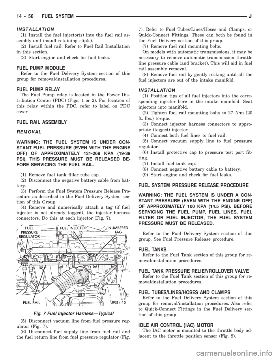
(4) Remove and numerically attach a tag (if fuel
injector is not already tagged), the injector harness
connectors. Do this at each injector (Fig. 7).
(5) Disconnect vacuum line from fuel pressure reg-
ulator (Fig. 7).
(6) Disconnect fuel supply line from fuel rail and
the fuel return line from fuel pressure regulator (Fig.7). Refer to Fuel Tubes/Lines/Hoses and Clamps, or
Quick-Connect Fittings. These can both be found in
the Fuel Delivery section of this group.
(7) Remove fuel rail mounting bolts.
On models with automatic transmissions, it may be
necessary to remove automatic transmission throttle
line pressure cable (and bracket). This will aid in fuel
rail assembly removal.
(8) Remove fuel rail by gently rocking until all the
fuel injectors are out of the intake manifold.
INSTALLATION
(1) Position tips of all fuel injectors into the corre-
sponding injector bore in the intake manifold. Seat
injectors into manifold.
(2) Tighten fuel rail mounting bolts to 27 Nzm (20
ft. lbs.) torque.
(3) Connect injector harness connectors to appro-
priate (tagged) injector.
(4) Connect both fuel lines to fuel rail.
(5) Connect vacuum supply line to fuel pressure
regulator.
(6) Install protective cap to pressure test port fit-
ting.
(7) Install fuel tank cap.
(8) Connect negative battery cable to battery.
(9) Start engine and check for fuel leaks.
FUEL SYSTEM PRESSURE RELEASE PROCEDURE
WARNING: THE FUEL SYSTEM IS UNDER A CON-
STANT PRESSURE (EVEN WITH THE ENGINE OFF)
OF APPROXIMATELY 100 KPA (14.5 PSI). BEFORE
SERVICING THE FUEL PUMP, FUEL LINES, FUEL
FILTER OR FUEL INJECTOR, THE FUEL SYSTEM
PRESSURE MUST BE RELEASED.
Refer to the Fuel Delivery System section of this
group. See Fuel Pressure Release procedure.
FUEL TANKS
Refer to the Fuel Tank section of this group for re-
moval/installation procedures.
FUEL TANK PRESSURE RELIEF/ROLLOVER VALVE
Refer to the Fuel Tank section of this group for re-
moval/installation procedures.
FUEL TUBES/LINES/HOSES AND CLAMPS
Refer to the Fuel Delivery System section of this
group for removal/installation procedures. Also refer
to Quick-Connect Fittings in the Fuel Delivery sec-
tion of this group.
IDLE AIR CONTROL (IAC) MOTOR
The IAC motor is mounted to the throttle body ad-
jacent to the throttle position sensor (Fig. 8).
Fig. 7 Fuel Injector HarnessÐTypical
14 - 56 FUEL SYSTEMJ
Page 143 of 1784
(3) Lower the vehicle.
PARK NEUTRAL SWITCH
Refer to Group 21, Transmissions for park neutral
switch service.
POWER STEERING PRESSURE SWITCHÐ2.5L
ENGINE ONLY
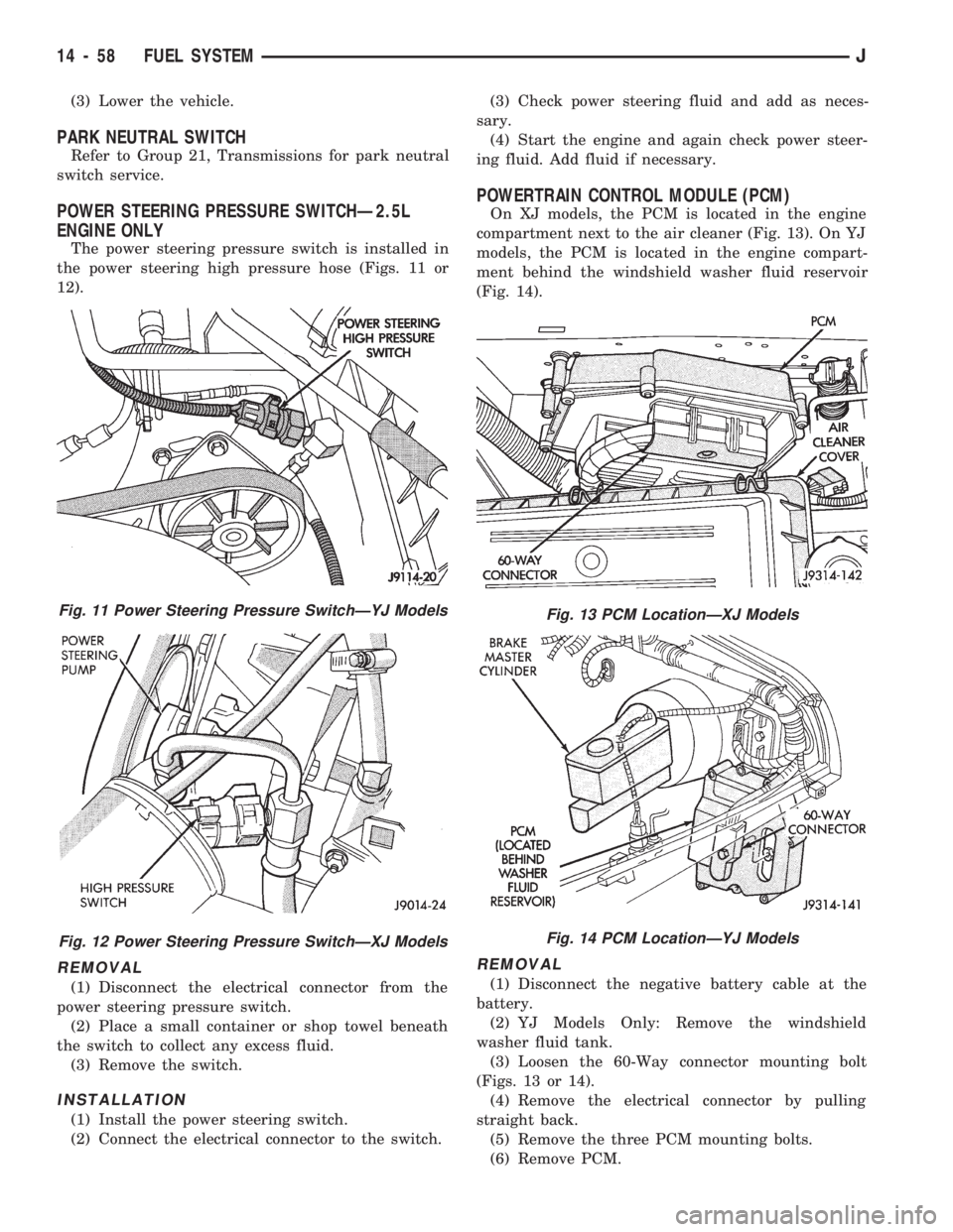
The power steering pressure switch is installed in
the power steering high pressure hose (Figs. 11 or
12).
REMOVAL
(1) Disconnect the electrical connector from the
power steering pressure switch.
(2) Place a small container or shop towel beneath
the switch to collect any excess fluid.
(3) Remove the switch.
INSTALLATION
(1) Install the power steering switch.
(2) Connect the electrical connector to the switch.(3) Check power steering fluid and add as neces-
sary.
(4) Start the engine and again check power steer-
ing fluid. Add fluid if necessary.
POWERTRAIN CONTROL MODULE (PCM)
On XJ models, the PCM is located in the engine
compartment next to the air cleaner (Fig. 13). On YJ
models, the PCM is located in the engine compart-
ment behind the windshield washer fluid reservoir
(Fig. 14).
REMOVAL
(1) Disconnect the negative battery cable at the
battery.
(2) YJ Models Only: Remove the windshield
washer fluid tank.
(3) Loosen the 60-Way connector mounting bolt
(Figs. 13 or 14).
(4) Remove the electrical connector by pulling
straight back.
(5) Remove the three PCM mounting bolts.
(6) Remove PCM.
Fig. 11 Power Steering Pressure SwitchÐYJ Models
Fig. 12 Power Steering Pressure SwitchÐXJ Models
Fig. 13 PCM LocationÐXJ Models
Fig. 14 PCM LocationÐYJ Models
14 - 58 FUEL SYSTEMJ
Page 144 of 1784
INSTALLATION
(1) After the PCM electrical connector has been
separated from the PCM, inspect the pins for corro-
sion, being spread apart, bent or misaligned. Also in-
spect the pin heights in the connector. If the pin
heights are different, this would indicate a pin has
separated from the connector. Repair as necessary.
(2) Install PCM. Tighten three mounting bolts to 1
Nzm (9 in. lbs.) torque.
(3) Engage 60-way connector into PCM. Tighten
connector mounting bolt to 4 Nzm (35 in. lbs.) torque.
(4) YJ Models: Install windshield washer fluid
tank.
(5) Connect negative cable to battery.
QUICK-CONNECT FITTINGS
Refer to the Fuel Delivery System section of this
group for removal/installation procedures.
THROTTLE BODY
REMOVAL
(1) Disconnect the negative battery cable.
(2) Disconnect air cleaner hose from throttle body.
(3) Disconnect idle air control motor and throttle
position sensor wire connectors.
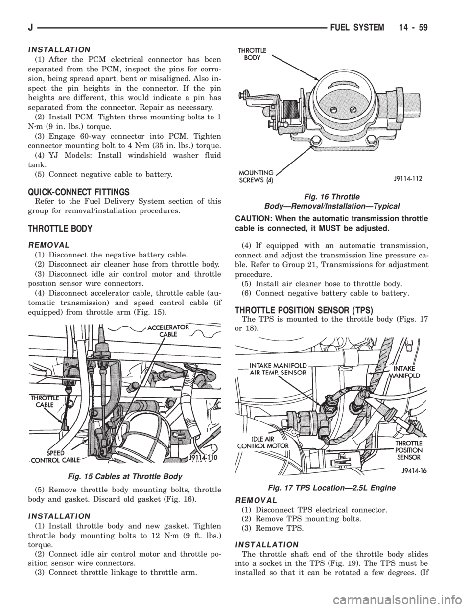
(4) Disconnect accelerator cable, throttle cable (au-
tomatic transmission) and speed control cable (if
equipped) from throttle arm (Fig. 15).
(5) Remove throttle body mounting bolts, throttle
body and gasket. Discard old gasket (Fig. 16).
INSTALLATION
(1) Install throttle body and new gasket. Tighten
throttle body mounting bolts to 12 Nzm (9 ft. lbs.)
torque.
(2) Connect idle air control motor and throttle po-
sition sensor wire connectors.
(3) Connect throttle linkage to throttle arm.CAUTION: When the automatic transmission throttle
cable is connected, it MUST be adjusted.
(4) If equipped with an automatic transmission,
connect and adjust the transmission line pressure ca-
ble. Refer to Group 21, Transmissions for adjustment
procedure.
(5) Install air cleaner hose to throttle body.
(6) Connect negative battery cable to battery.
THROTTLE POSITION SENSOR (TPS)
The TPS is mounted to the throttle body (Figs. 17
or 18).
REMOVAL
(1) Disconnect TPS electrical connector.
(2) Remove TPS mounting bolts.
(3) Remove TPS.
INSTALLATION
The throttle shaft end of the throttle body slides
into a socket in the TPS (Fig. 19). The TPS must be
installed so that it can be rotated a few degrees. (If
Fig. 16 Throttle
BodyÐRemoval/InstallationÐTypical
Fig. 17 TPS LocationÐ2.5L Engine
Fig. 15 Cables at Throttle Body
JFUEL SYSTEM 14 - 59
Page 262 of 1784
through the relay. When coolant temperature is be-
low 88ÉC (190ÉF), the PCM opens the ground path to
the relay. This will prevent the cooling fan from be-
ing energized.
Whenever the air conditioning is used, the PCM
engages the auxiliary cooling fan. It provides a
ground path to the cooling fan relay.
DIAGNOSIS
The powertrain control module (PCM) will enter a
diagnostic trouble code (DTC) number 35 in memory
if it detects a problem in the auxiliary cooling fan re-
lay or circuit. This will be read as a flashing signal
at the instrument panel mounted Malfunction Indica-
tor Lamp (formerly referred to as the Check Engine
Lamp). Refer to On-Board Diagnostics in Group 14,
Fuel Systems for information on accessing a DTC.
The DTC can also be accessed through the DRB
scan tool. Refer to the appropriate Powertrain Diag-
nostic Procedures manual for diagnostic information
and operation of the DRB scan tool.
REMOVAL
The auxiliary fan is attached to the radiator upper
crossmember behind the radiator.
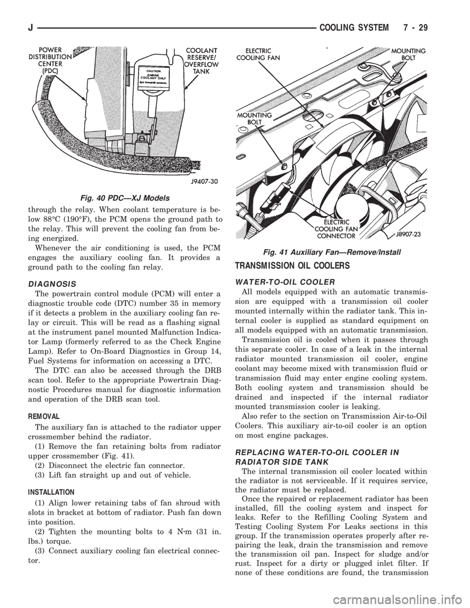
(1) Remove the fan retaining bolts from radiator
upper crossmember (Fig. 41).
(2) Disconnect the electric fan connector.
(3) Lift fan straight up and out of vehicle.
INSTALLATION
(1) Align lower retaining tabs of fan shroud with
slots in bracket at bottom of radiator. Push fan down
into position.
(2) Tighten the mounting bolts to 4 Nzm (31 in.
lbs.) torque.
(3) Connect auxiliary cooling fan electrical connec-
tor.
TRANSMISSION OIL COOLERS
WATER-TO-OIL COOLER
All models equipped with an automatic transmis-
sion are equipped with a transmission oil cooler
mounted internally within the radiator tank. This in-
ternal cooler is supplied as standard equipment on
all models equipped with an automatic transmission.
Transmission oil is cooled when it passes through
this separate cooler. In case of a leak in the internal
radiator mounted transmission oil cooler, engine
coolant may become mixed with transmission fluid or
transmission fluid may enter engine cooling system.
Both cooling system and transmission should be
drained and inspected if the internal radiator
mounted transmission cooler is leaking.
Also refer to the section on Transmission Air-to-Oil
Coolers. This auxiliary air-to-oil cooler is an option
on most engine packages.
REPLACING WATER-TO-OIL COOLER IN
RADIATOR SIDE TANK
The internal transmission oil cooler located within
the radiator is not serviceable. If it requires service,
the radiator must be replaced.
Once the repaired or replacement radiator has been
installed, fill the cooling system and inspect for
leaks. Refer to the Refilling Cooling System and
Testing Cooling System For Leaks sections in this
group. If the transmission operates properly after re-
pairing the leak, drain the transmission and remove
the transmission oil pan. Inspect for sludge and/or
rust. Inspect for a dirty or plugged inlet filter. If
none of these conditions are found, the transmission
Fig. 40 PDCÐXJ Models
Fig. 41 Auxiliary FanÐRemove/Install
JCOOLING SYSTEM 7 - 29
Page 939 of 1784
INTAKE MANIFOLDÐ2.5L ENGINE
REMOVAL
(1) Disconnect the battery negative cable.
(2) Remove the air inlet hose from the throttle
body and air cleaner.
(3) Loosen the accessory drive belt tension and re-
move the belt from the power steering pump.
(4) Remove the power steering pump and brackets
from the water pump and intake manifold. Support
power steering pump and bracket with mechanics
wire attached to the radiator upper crossmember.
(5) Remove the fuel tank filler cap to relieve the
fuel tank pressure.
(6) Install the fuel tank filler cap.
(7) Disconnect fuel supply and return tube from
the fuel rail (refer to Group 14, Fuel System - Quick
Connect Fittings).
(8) Disconnect the accelerator cable from the throt-
tle body and the holddown bracket.
CAUTION: When disconnecting the cruise control
connector at the throttle body, DO NOT pry the con-
nector off with pliers or screwdriver. Use finger
pressure only. Prying the connector off could break
it.
(9) Disconnect the electrical connectors. Pull the
harnesses away from the manifold.
²The throttle position sensor.
²The idle speed control motor.
²The coolant temperature sensor at the thermostat.
²The manifold air temperature sensor at the intake
manifold.
²The fuel injectors.
²The oxygen sensor.
(10) Disconnect the crankcase ventilation (CCV)
vacuum hose and manifold absolute pressure (MAP)
sensor vacuum hose connector at the intake mani-
fold.
(11) Disconnect vacuum hose from vacuum port on
the intake manifold.
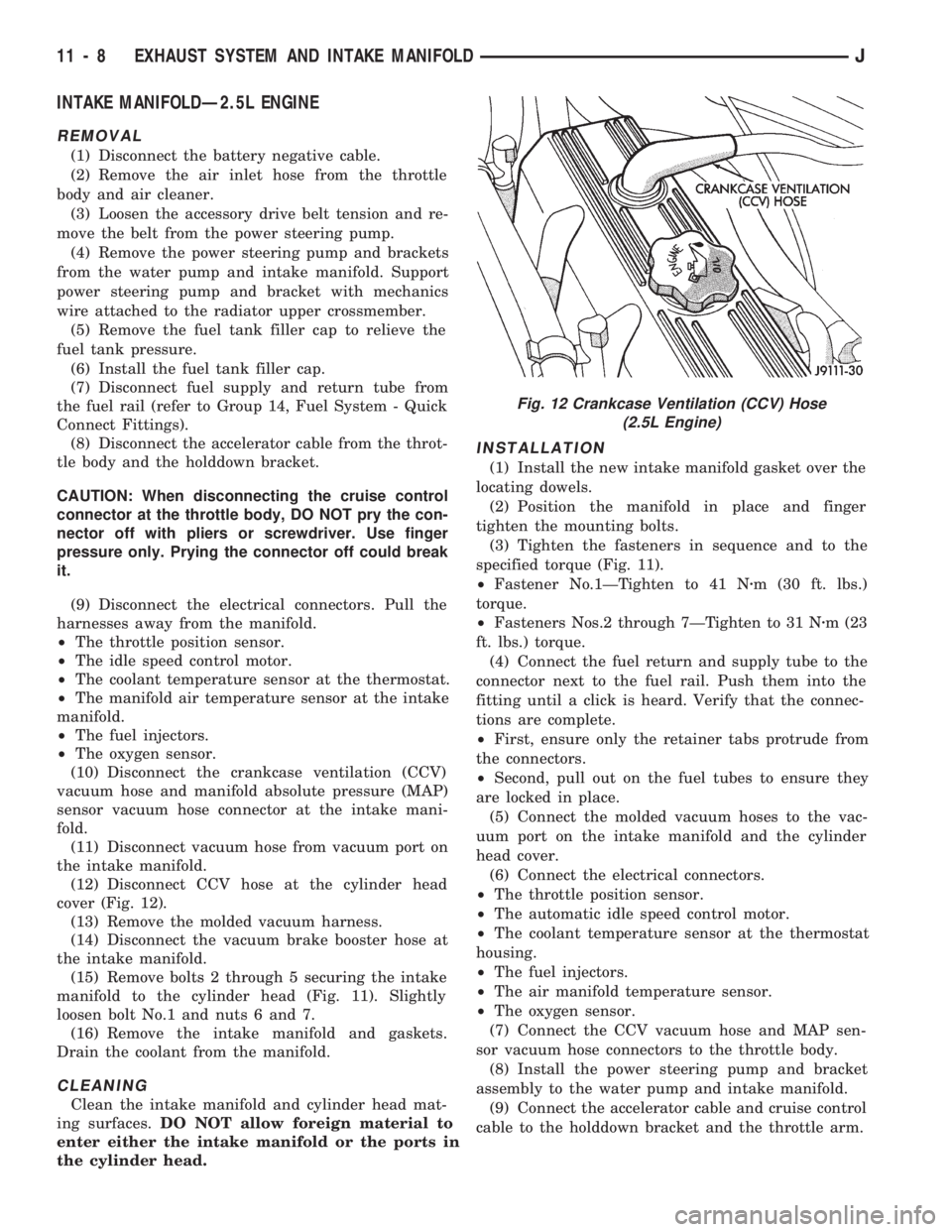
(12) Disconnect CCV hose at the cylinder head
cover (Fig. 12).
(13) Remove the molded vacuum harness.
(14) Disconnect the vacuum brake booster hose at
the intake manifold.
(15) Remove bolts 2 through 5 securing the intake
manifold to the cylinder head (Fig. 11). Slightly
loosen bolt No.1 and nuts 6 and 7.
(16) Remove the intake manifold and gaskets.
Drain the coolant from the manifold.
CLEANING
Clean the intake manifold and cylinder head mat-
ing surfaces.DO NOT allow foreign material to
enter either the intake manifold or the ports in
the cylinder head.
INSTALLATION
(1) Install the new intake manifold gasket over the
locating dowels.
(2) Position the manifold in place and finger
tighten the mounting bolts.
(3) Tighten the fasteners in sequence and to the
specified torque (Fig. 11).
²Fastener No.1ÐTighten to 41 Nzm (30 ft. lbs.)
torque.
²Fasteners Nos.2 through 7ÐTighten to 31 Nzm (23
ft. lbs.) torque.
(4) Connect the fuel return and supply tube to the
connector next to the fuel rail. Push them into the
fitting until a click is heard. Verify that the connec-
tions are complete.
²First, ensure only the retainer tabs protrude from
the connectors.
²Second, pull out on the fuel tubes to ensure they
are locked in place.
(5) Connect the molded vacuum hoses to the vac-
uum port on the intake manifold and the cylinder
head cover.
(6) Connect the electrical connectors.
²The throttle position sensor.
²The automatic idle speed control motor.
²The coolant temperature sensor at the thermostat
housing.
²The fuel injectors.
²The air manifold temperature sensor.
²The oxygen sensor.
(7) Connect the CCV vacuum hose and MAP sen-
sor vacuum hose connectors to the throttle body.
(8) Install the power steering pump and bracket
assembly to the water pump and intake manifold.
(9) Connect the accelerator cable and cruise control
cable to the holddown bracket and the throttle arm.
Fig. 12 Crankcase Ventilation (CCV) Hose
(2.5L Engine)
11 - 8 EXHAUST SYSTEM AND INTAKE MANIFOLDJ
Page 955 of 1784

YJ BUMPERS AND FRAME ATTACHED COMPONENTS
INDEX
page page
Generator Splash Shield................... 14
Body.................................. 18
Engine Front Support Cushion............... 15
Frame Crossmember Cover................. 14
Front Bumper........................... 14
Fuel and Brake Fluid Tube Retainer Clip....... 16
Fuel Filter Shield and Bracket............... 17
Fuel Tank Skid Plate...................... 16Muffler and Tailpipe Heat Shields............ 17
Muffler/Tailpipe Hanger Bracket.............. 16
Rear Bumper............................ 18
Rear Jounce Bumper..................... 18
Service Information....................... 14
Tow Hooks............................. 14
Transfer Case Skid Plate.................. 15
SERVICE INFORMATION
In some cases, components in the following proce-
dures either support, or are hidden by other compo-
nents.
FRONT BUMPER
The YJ front bumper is a one-piece rail (Fig. 1). A
front crossmember cover (Fig. 1) is also installed on
all YJ vehicles.
BUMPER REMOVAL
(1) Disconnect and remove the fog lamps, if
equipped.
(2) Remove the nuts and bolts that retain the
bumper extensions to the bumper rail and remove
the extensions.
(3) Remove the nuts and bolts that attach the
bumper rail/tow hooks to the frame rails.(4) Remove the bumper rail from the frame rails.
BUMPER INSTALLATION
(1) Position the front bumper on the frame rails.
(2) Install the bolts and attach the front bumper
rail (and tow hooks, if equipped) to the frame rails.
(3) Tighten the bolts to 102 Nzm (75 ft-lbs) torque.
(4) Position the bumper extensions on the bumper
rail and install the retaining bolts.
(5) Tighten the bolts to 104 Nzm (77 ft-lbs) torque.
(6) Install the fog lamps, if equipped.
FRAME CROSSMEMBER COVER
REMOVAL
(1) Remove the screws that attach the crossmem-
ber cover and support to the frame rails.
(2) Remove the crossmember cover and support
from the frame rails.
INSTALLATION
(1) Position the support and crossmember cover on
the frame rails.
(2) Install the attaching screws.
(3) Tighten the screws to 8 Nzm (72 in-lbs) torque.
TOW HOOKS
REMOVAL
(1) Remove the two bolts that attach the tow hook
to the bumper rail and to the frame rail.
(2) Remove the tow hook.
INSTALLATION
(1) Position the tow hook on the bumper rail and
frame rail.
(2) Install the attaching bolts.
(3) Tighten the bolts to 102 Nzm (75 ft-lbs) torque.
GENERATOR SPLASH SHIELD
REMOVAL
(1) Remove the shield retaining nut and washer
(Fig. 2) from the engine oil pan stud (2.5L engines
only).
Fig. 1 Front Bumper Rail, Crossmember Cover &
Tow Hooks
13 - 14 FRAME AND BUMPERSJ
Page 957 of 1784
FUEL TANK SKID PLATE
REMOVAL
(1) Position a support under the fuel tank skid
plate.
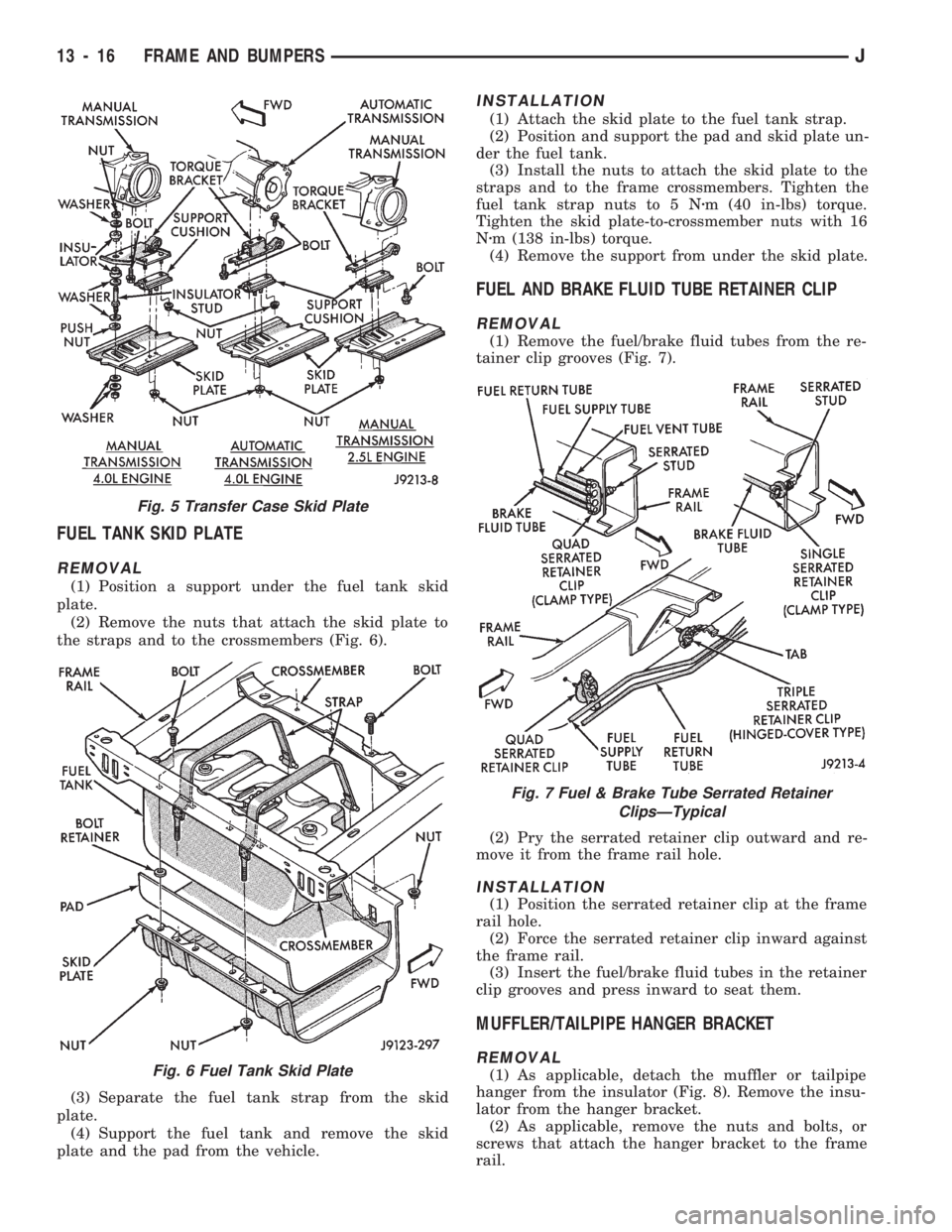
(2) Remove the nuts that attach the skid plate to
the straps and to the crossmembers (Fig. 6).
(3) Separate the fuel tank strap from the skid
plate.
(4) Support the fuel tank and remove the skid
plate and the pad from the vehicle.
INSTALLATION
(1) Attach the skid plate to the fuel tank strap.
(2) Position and support the pad and skid plate un-
der the fuel tank.
(3) Install the nuts to attach the skid plate to the
straps and to the frame crossmembers. Tighten the
fuel tank strap nuts to 5 Nzm (40 in-lbs) torque.
Tighten the skid plate-to-crossmember nuts with 16
Nzm (138 in-lbs) torque.
(4) Remove the support from under the skid plate.
FUEL AND BRAKE FLUID TUBE RETAINER CLIP
REMOVAL
(1) Remove the fuel/brake fluid tubes from the re-
tainer clip grooves (Fig. 7).
(2) Pry the serrated retainer clip outward and re-
move it from the frame rail hole.
INSTALLATION
(1) Position the serrated retainer clip at the frame
rail hole.
(2) Force the serrated retainer clip inward against
the frame rail.
(3) Insert the fuel/brake fluid tubes in the retainer
clip grooves and press inward to seat them.
MUFFLER/TAILPIPE HANGER BRACKET
REMOVAL
(1) As applicable, detach the muffler or tailpipe
hanger from the insulator (Fig. 8). Remove the insu-
lator from the hanger bracket.
(2) As applicable, remove the nuts and bolts, or
screws that attach the hanger bracket to the frame
rail.
Fig. 5 Transfer Case Skid Plate
Fig. 6 Fuel Tank Skid Plate
Fig. 7 Fuel & Brake Tube Serrated Retainer
ClipsÐTypical
13 - 16 FRAME AND BUMPERSJ