1994 JEEP CHEROKEE engine coolant
[x] Cancel search: engine coolantPage 1685 of 1784
CLIMATE CONTROL SYSTEMÐXJ VEHICLES
INDEX
page page
A/C Recirculating Air Door Vacuum Motor
Replacement.......................... 31
Blower Motor Resistors Replacement......... 35
Blower Motor/Fan Replacement.............. 26
CondenserÐ4.0L Engines.................. 32
Condenser/Receiver DrierÐ2.5L Engines....... 31
Defroster Duct Replacement................ 29
Description............................. 22
Evaporator Coil.......................... 34
Evaporator/Blower Housing................. 33Expansion (H) Valve...................... 35
Heater and A/C Control Panel Replacement.... 26
Heater Control Cable Replacement........... 30
Heater Core............................ 28
Heater Core Housing Replacement........... 29
Heater/Defroster/Instrument Panel Outlet Door
Vacuum Motor Replacement............... 30
Receiver DrierÐ4.0L Engines............... 32
Temperature Control Thermostat............. 35
DESCRIPTION
The Climate Control System combines air condi-
tioning, heating and ventilating capabilities for vehi-
cles equipped with air conditioning. Vehicles without
air conditioning perform heating and ventilating
functions without the air conditioning evaporator.
Both systems consist basically of 2 parts:
²Blower and Air Inlet Assembly
²Heater Core and Air Distribution Assembly
These assemblies, initially installed as a single
unit, may be removed separately from under the in-
strument panel as required for service.
HEATER SYSTEM
The heater system is a blend air type. Outside air
is heated and then blended in varying amounts with
cooler outside air to obtain the desired discharge
temperature. A heater coolant valve provides full
flow to the heater core for all heating modes. The
heater coolant valve remains closed for the ventila-
tion mode, allowing discharge air to approach the
outside ambient air temperature.
AIR CONDITIONING SYSTEM
The air conditioning system has an evaporator to
cool and dehumidify the incoming outside air prior to
blending with the heated air. The evaporator is in
operation during the A/C mode and also in the de-
frost mode for defogging purposes. The evaporator is
not in operation at ambient temperatures below ap-
proximately -1ÉC (30ÉF). To maintain minimum evap-
orator temperature, a fixed thermostat setting switch
cycles the compressor clutch. The blower is operatingthe heater or air conditioning systems, except the
OFF mode. In this mode (OFF) the blower and the
outside air are shut off.
The cooling unit is mounted on the dash panel and
the cooled air is discharged from the instrument
panel registers. The registers are adjusted to provide
general or localized cooling.
SIGHT GLASS
The sight glass is located on top of the receiver/
drier. The sight glass provides a visual check of the
system refrigerant level. A continuous stream of bub-
bles will appear in the sight glass when the system
charge is low. Bubbles will not appear when the sys-
tem is fully charged.
LOW PRESSURE SWITCH
The low pressure switch disengages the magnetic
clutch if the pressure in the system drops below 193
kPa (28 psi). This will occur with a loss in refriger-
ant or with cold ambient temperature.
HEATER VALVE
The heater valve regulates coolant flow to the
heater core. It requires vacuum to shut off flow to
the heater core.
These vehicles are equipped with a bypass-type
heater water valve. When the heater valve is closed,
coolant flow to the heater core is bypassed back to
the engine. When the heater valve is open, coolant is
directed through the heater core and back to the en-
gine.
24 - 22 HEATING AND AIR CONDITIONINGJ
Page 1690 of 1784
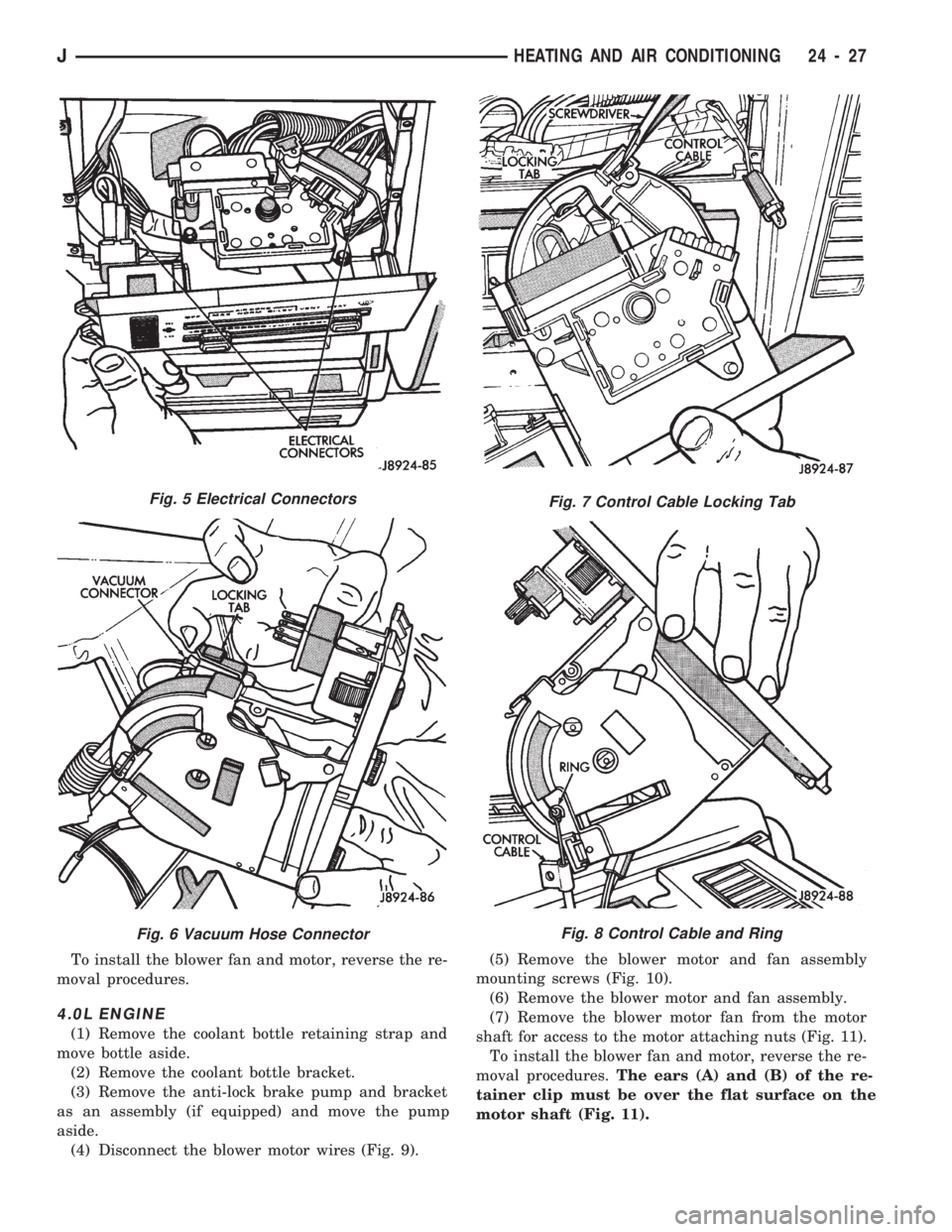
To install the blower fan and motor, reverse the re-
moval procedures.
4.0L ENGINE
(1) Remove the coolant bottle retaining strap and
move bottle aside.
(2) Remove the coolant bottle bracket.
(3) Remove the anti-lock brake pump and bracket
as an assembly (if equipped) and move the pump
aside.
(4) Disconnect the blower motor wires (Fig. 9).(5) Remove the blower motor and fan assembly
mounting screws (Fig. 10).
(6) Remove the blower motor and fan assembly.
(7) Remove the blower motor fan from the motor
shaft for access to the motor attaching nuts (Fig. 11).
To install the blower fan and motor, reverse the re-
moval procedures.The ears (A) and (B) of the re-
tainer clip must be over the flat surface on the
motor shaft (Fig. 11).
Fig. 5 Electrical Connectors
Fig. 6 Vacuum Hose Connector
Fig. 7 Control Cable Locking Tab
Fig. 8 Control Cable and Ring
JHEATING AND AIR CONDITIONING 24 - 27
Page 1700 of 1784
CLIMATE CONTROL SYSTEMÐYJ VEHICLES
INDEX
page page
A/C Blower Motor........................ 43
A/C Condenser.......................... 42
A/C Control Panel........................ 41
Blower Motor (Heating).................... 40
Blower Motor/Air Door Motor Switch Replacement . 39
Defroster Nozzle and Duct................. 40
Description (Air Conditioning)................ 41
Description (Heating)...................... 37
Evaporator and Housing................... 42
Expansion (H) Valve...................... 43Fresh Air Door Vacuum Motor............... 41
Fresh Air Intake Duct..................... 41
Fresh Air Ventilation...................... 39
Heater Control Panel Replacement........... 39
Heater Core and Housing.................. 40
Heater/Defroster Operation................. 37
Receiver-Drier Replacement................ 42
Sight Glass............................. 41
Vent Door Control Cables.................. 39
DESCRIPTION (HEATING)
A blend-air heating system is used in YJ vehicles.
The blend-air system provides a constant flow of en-
gine coolant through the heater core.
The temperature of heated air entering the passen-
ger compartment is controlled by regulating the
quantity of air flow through the heater core. This is
accomplished by blending a controlled amount of un-
heated air from outside the vehicle with heated air
from the heater core.
HEATER/DEFROSTER OPERATION
The heater core is connected to the engine cooling
system. It operates on the circulation of heated en-
gine coolant through the core and a supply of fresh
air drawn in through the intake grille on the cowl.
Engine coolant flows through the heater core at all
times.
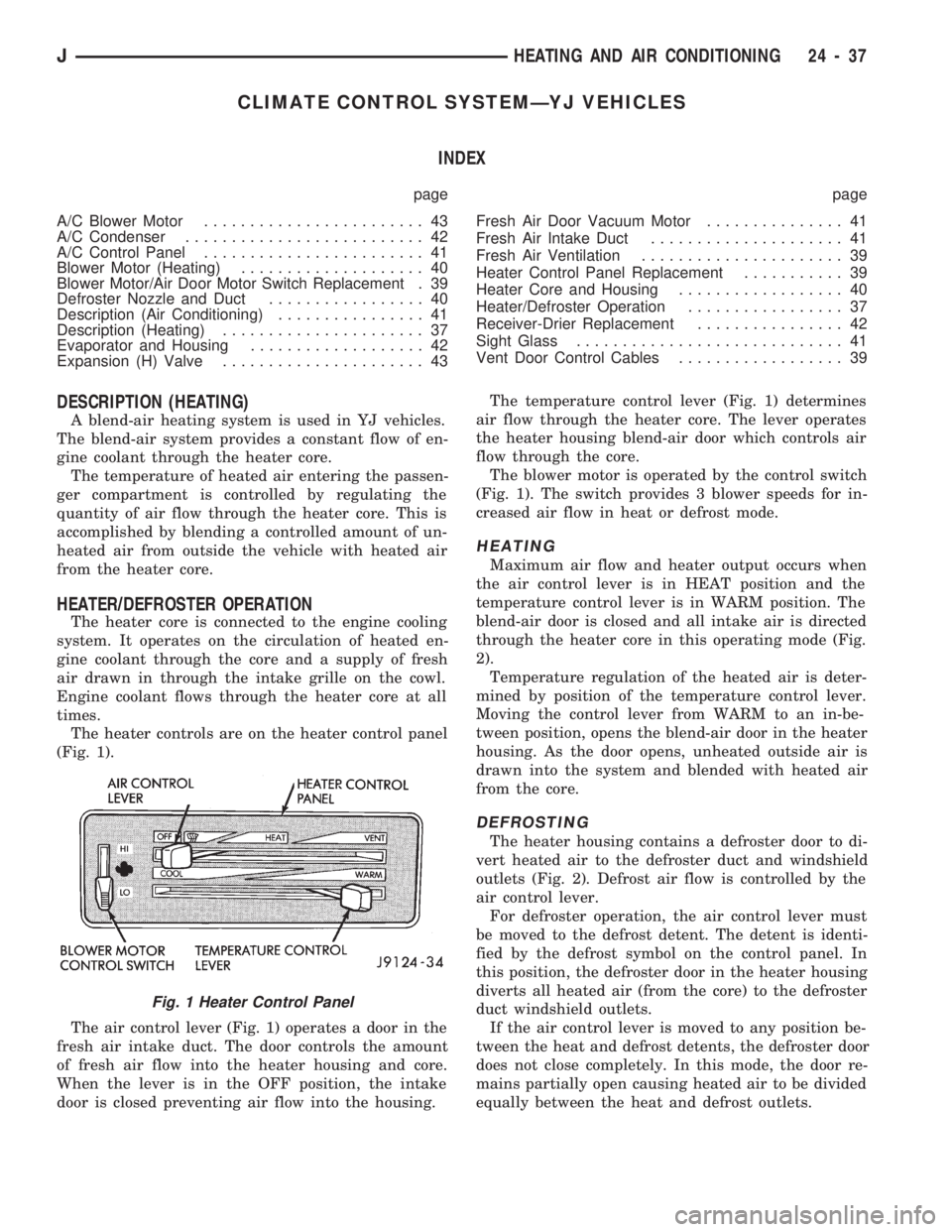
The heater controls are on the heater control panel
(Fig. 1).
The air control lever (Fig. 1) operates a door in the
fresh air intake duct. The door controls the amount
of fresh air flow into the heater housing and core.
When the lever is in the OFF position, the intake
door is closed preventing air flow into the housing.The temperature control lever (Fig. 1) determines
air flow through the heater core. The lever operates
the heater housing blend-air door which controls air
flow through the core.
The blower motor is operated by the control switch
(Fig. 1). The switch provides 3 blower speeds for in-
creased air flow in heat or defrost mode.
HEATING
Maximum air flow and heater output occurs when
the air control lever is in HEAT position and the
temperature control lever is in WARM position. The
blend-air door is closed and all intake air is directed
through the heater core in this operating mode (Fig.
2).
Temperature regulation of the heated air is deter-
mined by position of the temperature control lever.
Moving the control lever from WARM to an in-be-
tween position, opens the blend-air door in the heater
housing. As the door opens, unheated outside air is
drawn into the system and blended with heated air
from the core.
DEFROSTING
The heater housing contains a defroster door to di-
vert heated air to the defroster duct and windshield
outlets (Fig. 2). Defrost air flow is controlled by the
air control lever.
For defroster operation, the air control lever must
be moved to the defrost detent. The detent is identi-
fied by the defrost symbol on the control panel. In
this position, the defroster door in the heater housing
diverts all heated air (from the core) to the defroster
duct windshield outlets.
If the air control lever is moved to any position be-
tween the heat and defrost detents, the defroster door
does not close completely. In this mode, the door re-
mains partially open causing heated air to be divided
equally between the heat and defrost outlets.
Fig. 1 Heater Control Panel
JHEATING AND AIR CONDITIONING 24 - 37
Page 1703 of 1784
HEATER CORE AND HOUSING
REMOVAL
WARNING: HOT ENGINE COOLANT CAN CAUSE
SEVERE BURNS. DO NOT OPEN THE RADIATOR
DRAIN COCK WHEN THE COOLING SYSTEM IS
HOT AND PRESSURIZED. ALLOW THE COOLANT
TO DECREASE TO ROOM TEMPERATURE BEFORE
STARTING REPAIR OPERATIONS.
(1) Drain approximately 1.9 liters (2 qts) of coolant
from the radiator. Drain the coolant into a clean con-
tainer.
(2) Disconnect the heater hoses.
(3) Disconnect the vent door cables.
(4) Disconnect the blower motor wire.
(5) Disconnect the defroster duct.
(6) Remove the nuts that attach the heater hous-
ing studs to the engine compartment side of the dash
panel.
(7) Remove the heater housing assembly by tilting
it downward, to disengage it from the defroster duct.
Pull it rearward and out from under the instrument
panel.
(8) Remove the heater hosing cover from the hous-
ing.
(9) Remove the heater core from the housing.
INSTALLATION
(1) Install the heater core in the housing and in-
stall the cover on the housing.
(2) Position the heater housing on the dash panel.
Be sure the housing studs all extend through the
dash panel.
(3) Install the seals on the heater core outlet and
inlet tubes and over the blower motor housing.
(4) Install the attaching nuts on the housing studs.
CAUTION: DO NOT over tighten the attaching nuts.
The housing could become distorted causing air
leaks and improper heater door operation. Tighten
the nuts alternately and evenly until 2 stud threads
are visible beyond each nut.
(5) Connect the defroster duct to the housing.
(6) Connect the blower motor wire.
(7) Connect the vent door control cables.
(8) Connect the heater hoses.
(9) Fill and bleed the cooling system.
(10) Check system operation.
BLOWER MOTOR (HEATING)
REMOVAL
(1) Remove the heater housing.
(2) Remove the blower motor-to-heater housing at-
taching screws/nuts.
(3) Remove the blower motor from the housing.
INSTALLATION
(1) Position the blower motor into the housing.
(2) Install and tighten the blower motor-to-heater
housing attaching screws/nuts.
(3) Install the heater housing.
(4) Check blower motor and heater operation.
DEFROSTER NOZZLE AND DUCT
REMOVAL
WARNING: HOT ENGINE COOLANT CAN CAUSE
SEVERE BURNS. DO NOT OPEN THE RADIATOR
DRAIN COCK WHEN THE COOLING SYSTEM IS
HOT AND PRESSURIZED. ALLOW THE COOLANT
TO DECREASE TO ROOM TEMPERATURE BEFORE
STARTING REPAIR OPERATIONS.
(1) Drain approximately 1.9 liters (2 qts) of coolant
from the radiator. Drain the coolant into a clean con-
tainer.
(2) Disconnect the heater hoses.
(3) Remove the nuts attaching the heater housing
studs to the engine compartment side of the dash
panel.
(4) Disconnect the speedometer cable.
(5) Remove the glove box.
(6) Tilt the heater housing back and pull it rear-
ward and out from under the instrument panel.
(7) Disconnect the vent control cables.
(8) Remove the fresh air intake grille from the
cowl.
(9) Remove the fresh air intake duct.
(10) Lower the windshield.
(11) Remove the defroster nozzle attaching screws
and remove the nozzle and duct.
INSTALLATION
(1) Install the defroster nozzle and duct.
(2) Raise and secure the windshield.
(3) Install the fresh air intake duct.
(4) Install the fresh air intake grille on the cowl.
(5) Install the vent cables.
(6) Position the heater housing on the dash panel.
Be sure all the housing studs extend through the
dash panel.
(7) Install the seals on the blower motor and the
heater core inlet and outlet tubes.
(8) Install the attaching nuts on the housing studs.
CAUTION: DO NOT over tighten the attaching nuts.
The housing could become distorted causing air
leaks and improper heater door operation. Tighten
the nuts alternately and evenly until 2 stud threads
are visible beyond each nut.
(9) Install the glove box.
(10) Connect the speedometer cable.
(11) Connect the heater hoses.
24 - 40 HEATING AND AIR CONDITIONINGJ
Page 1704 of 1784
(12) Fill and bleed the cooling system.
FRESH AIR DOOR VACUUM MOTOR
REMOVAL
(1) Remove the glove box and assist handle.
(2) Disconnect the vacuum hose from the motor.
(3) Remove the motor lever retaining clip.
(4) Remove the motor attaching nuts and remove
the motor from the fresh air duct.
INSTALLATION
(1) Position the motor on the fresh air duct and in-
stall the motor attaching nuts.
(2) Align the motor lever with the air door lever
and install the lever retaining clip.
(3) Connect the vacuum hose to the motor.
(4) Install the glove box and assist handle.
FRESH AIR INTAKE DUCT
REMOVAL
WARNING: HOT ENGINE COOLANT CAN CAUSE
SEVERE BURNS. DO NOT OPEN THE RADIATOR
DRAIN COCK WHEN THE COOLING SYSTEM IS
HOT AND PRESSURIZED. ALLOW THE COOLANT
TO DECREASE TO ROOM TEMPERATURE BEFORE
STARTING REPAIR OPERATIONS.
(1) Drain approximately 1.9 liters (2 qts) of coolant
from the radiator. Drain the coolant into a clean con-
tainer.
(2) Disconnect the heater hoses.
(3) Remove the nuts attaching the heater housing
studs to the dash panel from inside the engine com-
partment.
(4) Disconnect the speedometer cable.
(5) Remove the glove box and assist handle.
(6) Tilt the heater housing back and pull it rear-
ward and out from under the instrument panel.
(7) Disconnect the vent cables.
(8) Remove the fresh air intake grille from the
cowl.
(9) Remove the fresh air intake duct.
INSTALLATION
(1) Install the fresh air intake duct.
(2) Install the defroster nozzle and duct.
(3) Raise and secure the windshield.
(4) Install the fresh air grille on the cowl.
(5) Install the vent cables.
(6) Position the heater housing on the dash panel.
Be sure all the housing studs extend through the
dash panel.
(7) Install the seals on the blower motor and
heater core inlet and outlet tubes.
(8) Install the attaching nuts on the heater hous-
ing studs.CAUTION: DO NOT over tighten the attaching nuts.
The housing could become distorted causing air
leaks and improper heater door operation. Tighten
the nuts alternately and evenly until 2 stud threads
are visible beyond each nut.
(9) Install the glove box and assist handle.
(10) Connect the speedometer cable.
(11) Connect the heater hoses.
(12) Fill and bleed the cooling system.
DESCRIPTION (AIR CONDITIONING)
The evaporator, blower fan and motor, thermostat,
expansion valve, capillary tube, air outlets and sys-
tem controls are located in the evaporator housing.
The evaporator housing is mounted under the instru-
ment panel. The compressor, condenser, receiver-
dryer and refrigerant lines are located in the engine
compartment.
A rotary-type compressor with magnetic clutch op-
erated drive pulley is used for all vehicles equipped
with air conditioning.
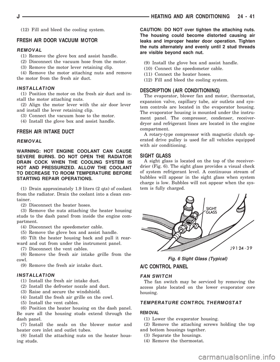
SIGHT GLASS
A sight glass is located on the top of the receiver-
drier (Fig. 6). The sight glass provides a visual check
of system refrigerant level. A continuous stream of
bubbles will appear in the sight glass when system
charge is low. Bubbles will not appear when the sys-
tem is fully charged.
A/C CONTROL PANEL
FAN SWITCH
The fan switch may be serviced by removing the
access plate located on the lower evaporator core
housing.
TEMPERATURE CONTROL THERMOSTAT
REMOVAL
(1) Lower the evaporator housing.
(2) Remove the attaching screws holding the top
and bottom housings together.
(3) Separate the housings.
(4) Remove the thermostat.
Fig. 6 Sight Glass (Typical)
JHEATING AND AIR CONDITIONING 24 - 41
Page 1705 of 1784
INSTALLATION
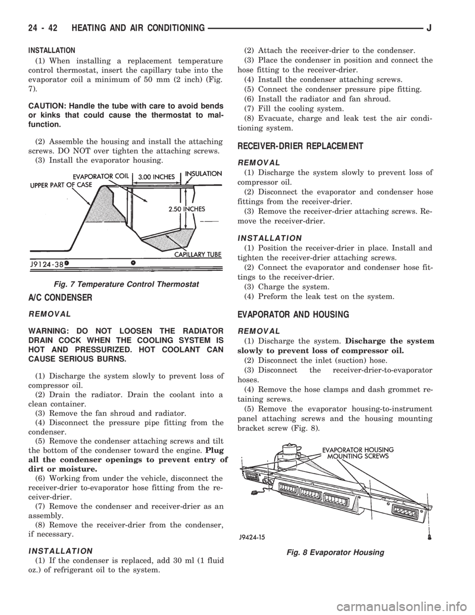
(1) When installing a replacement temperature
control thermostat, insert the capillary tube into the
evaporator coil a minimum of 50 mm (2 inch) (Fig.
7).
CAUTION: Handle the tube with care to avoid bends
or kinks that could cause the thermostat to mal-
function.
(2) Assemble the housing and install the attaching
screws. DO NOT over tighten the attaching screws.
(3) Install the evaporator housing.
A/C CONDENSER
REMOVAL
WARNING: DO NOT LOOSEN THE RADIATOR
DRAIN COCK WHEN THE COOLING SYSTEM IS
HOT AND PRESSURIZED. HOT COOLANT CAN
CAUSE SERIOUS BURNS.
(1) Discharge the system slowly to prevent loss of
compressor oil.
(2) Drain the radiator. Drain the coolant into a
clean container.
(3) Remove the fan shroud and radiator.
(4) Disconnect the pressure pipe fitting from the
condenser.
(5) Remove the condenser attaching screws and tilt
the bottom of the condenser toward the engine.Plug
all the condenser openings to prevent entry of
dirt or moisture.
(6) Working from under the vehicle, disconnect the
receiver-drier to-evaporator hose fitting from the re-
ceiver-drier.
(7) Remove the condenser and receiver-drier as an
assembly.
(8) Remove the receiver-drier from the condenser,
if necessary.
INSTALLATION
(1) If the condenser is replaced, add 30 ml (1 fluid
oz.) of refrigerant oil to the system.(2) Attach the receiver-drier to the condenser.
(3) Place the condenser in position and connect the
hose fitting to the receiver-drier.
(4) Install the condenser attaching screws.
(5) Connect the condenser pressure pipe fitting.
(6) Install the radiator and fan shroud.
(7) Fill the cooling system.
(8) Evacuate, charge and leak test the air condi-
tioning system.
RECEIVER-DRIER REPLACEMENT
REMOVAL
(1) Discharge the system slowly to prevent loss of
compressor oil.
(2) Disconnect the evaporator and condenser hose
fittings from the receiver-drier.
(3) Remove the receiver-drier attaching screws. Re-
move the receiver-drier.
INSTALLATION
(1) Position the receiver-drier in place. Install and
tighten the receiver-drier attaching screws.
(2) Connect the evaporator and condenser hose fit-
tings to the receiver-drier.
(3) Charge the system.
(4) Preform the leak test on the system.
EVAPORATOR AND HOUSING
REMOVAL
(1) Discharge the system.Discharge the system
slowly to prevent loss of compressor oil.
(2) Disconnect the inlet (suction) hose.
(3) Disconnect the receiver-drier-to-evaporator
hoses.
(4) Remove the hose clamps and dash grommet re-
taining screws.
(5) Remove the evaporator housing-to-instrument
panel attaching screws and the housing mounting
bracket screw (Fig. 8).
Fig. 7 Temperature Control Thermostat
Fig. 8 Evaporator Housing
24 - 42 HEATING AND AIR CONDITIONINGJ
Page 1727 of 1784
Install air filter and cover.
(3) Install vacuum lines to housing.
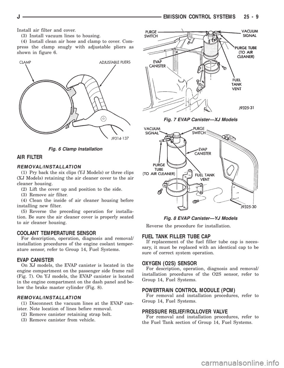
(4) Install clean air hose and clamp to cover. Com-
press the clamp snugly with adjustable pliers as
shown in figure 6.
AIR FILTER
REMOVAL/INSTALLATION
(1) Pry back the six clips (YJ Models) or three clips
(XJ Models) retaining the air cleaner cover to the air
cleaner housing.
(2) Lift the cover up and position to the side.
(3) Remove air filter.
(4) Clean the inside of air cleaner housing before
installing new filter.
(5) Reverse the preceding operation for installa-
tion. Be sure the air cleaner cover is properly seated
to air cleaner housing.
COOLANT TEMPERATURE SENSOR
For description, operation, diagnosis and removal/
installation procedures of the engine coolant temper-
ature sensor, refer to Group 14, Fuel Systems.
EVAP CANISTER
On XJ models, the EVAP canister is located in the
engine compartment on the passenger side frame rail
(Fig. 7). On YJ models, the EVAP canister is located
in the engine compartment on the dash panel and be-
low the brake master cylinder (Fig. 8).
REMOVAL/INSTALLATION
(1) Disconnect the vacuum lines at the EVAP can-
ister. Note location of lines before removal.
(2) Remove canister retaining strap bolt.
(3) Remove canister from vehicle.Reverse the procedure for installation.
FUEL TANK FILLER TUBE CAP
If replacement of the fuel filler tube cap is neces-
sary, it must be replaced with an identical cap to be
sure of correct system operation.
OXYGEN (O2S) SENSOR
For description, operation, diagnosis and removal/
installation procedures of the O2S sensor, refer to
Group 14, Fuel Systems.
POWERTRAIN CONTROL MODULE (PCM)
For removal and installation procedures, refer to
Group 14, Fuel Systems.
PRESSURE RELIEF/ROLLOVER VALVE
For removal and installation procedures, refer to
the Fuel Tank section of Group 14, Fuel Systems.
Fig. 7 EVAP CanisterÐXJ Models
Fig. 8 EVAP CanisterÐYJ Models
Fig. 6 Clamp Installation
JEMISSION CONTROL SYSTEMS 25 - 9
Page 1745 of 1784
30RH/32RH AUTOMATIC TRANSMISSION . . . 21-66
30RH/32RH GENERAL SPECIFICATIONS . . . 21-322
30RH/32RH IN-VEHICLE SERVICE.........21-96
30RH/32RH PRESSURE TEST
SPECIFICATIONS....................21-323
30RH/32RH SNAP RING/THRUST
WASHER/THRUST PLATE
SPECIFICATIONS....................21-322
30RH/32RH TORQUE SPECIFICATIONS....21-323
30RH/32RH TRANSMISSION DIAGNOSIS . . . 21-69,
21-77,21-78,21-79,21-80,21-81,21-82,21-83,21-84,
21-85
30RH/32RH TRANSMISSION OVERHAUL . . . 21-112
30RH/32RH TRANSMISSION REMOVAL
AND INSTALLATION..................21-108
3-2 DOWNSHIFT, HYDRAULIC FLOW
DURING FULL THROTTLE..............21-92
3-2 DOWNSHIFT, HYDRAULIC FLOW
DURING PART THROTTLE..............21-91
4WD INDICATOR......................8E-22
4WD INDICATOR INOPERATIVE............8E-4
4WD INDICATOR LAMP..................8E-2
60-WAY CONNECTOR, POWERTRAIN
CONTROL MODULE (PCM).............14-38
ABBREVIATIONS, SYMBOLS, FUSES........8W-6
ABS BRAKE DIAGNOSIS...................5-3
ABS BRAKES, BRAKE BLEEDINGÐWITH.....5-14
ABS COMPONENT SERVICE...............5-47
ABS FAULT DIAGNOSIS................5-4,5-6
ABS OPERATION IN ANTILOCK BRAKING
MODE..............................5-43
ABS OPERATION IN NORMAL BRAKING
MODE..............................5-43
ABS SYSTEM OPERATION................5-39
ABS SYSTEM WIRING AND ELECTRICAL
CIRCUITS............................5-4
ABS WARNING LIGHT DISPLAY.............5-3
ABSOLUTE PRESSURE (MAP) SENSOR,
MANIFOLD; FUEL SYSTEM.............14-57
ABSOLUTE PRESSURE (MAP) SENSOR,
MANIFOLD; IGNITION SYSTEMS....8D-5,8D-27
ABSOLUTE PRESSURE (MAP) SENSORÐ
PCM INPUT, MANIFOLD...............14-21
ABSOLUTE PRESSURE (MAP) SENSOR
TEST, MANIFOLD; FUEL SYSTEM........14-44
ABSOLUTE PRESSURE (MAP) SENSOR
TEST, MANIFOLD; IGNITION
SYSTEMS..........................8D-14
ABSORBER, SHOCK; FRONT
SUSPENSION AND AXLE............2-12,2-14
ABSORBER, SHOCK; REAR SUSPENSION
AND AXLES........................3-3,3-5
A/C BLOWER MOTOR...................24-43
A/C CONDENSER......................24-42
A/C CONTROL PANEL...................24-41
A/C CONTROL PANEL REPLACEMENT,
HEATER ............................24-26
A/C OPERATION........................24-1
A/C PERFORMANCE TEST................24-8
A/C RECIRCULATING AIR DOOR
VACUUM MOTOR REPLACEMENT........24-31
ACCELERATION SENSOR INSTALLATION.....5-52
ACCELERATION SENSOR REMOVAL........5-52
ACCELERATION SWITCH.................5-41
ACCELERATION SWITCH OPERATION.......5-45
ACCELERATOR PEDAL..................14-16
ACCELERATOR PEDAL AND THROTTLE
CABLE........................14-16,14-54
ACCENT PAINT.......................23-202
ACCESSORY DRIVE BELT.................0-20
ACCESSORY DRIVE BELTS, ENGINE........7-31
ACCUMULATOR PISTONS AND SPRINGS . . 21-179
ACTUATOR MOTOR STALL TEST...........8P-6
ADAPTER HOUSING AND PARK LOCK
COMPONENT OVERHAUL.............21-120
ADAPTER HOUSING SEAL REPLACEMENT . . 21-182
ADD-A-TRUNK.......................23-199
ADJUSTER PLUG ASSEMBLY
REPLACEMENT......................19-27
ADJUSTMENT, BRAKELIGHT SWITCH.......5-66
ADJUSTMENT, DIFFERENTIAL SHIM
PACK MEASUREMENT..................2-42
ADJUSTMENT, DOOR LATCH
.............23-55
ADJUSTMENT, DRUM BRAKE
..............5-35
ADJUSTMENT, FOG LAMP BEAM
..........8L-12
ADJUSTMENT, FRONT BAND
.............21-99ADJUSTMENT, HEADLAMP BEAM..........8L-3
ADJUSTMENT, HOOD....................23-9
ADJUSTMENT, LIFTGATE................23-70
ADJUSTMENTÐMAJOR, DOOR
ALIGNMENT.........................23-47
ADJUSTMENTÐMINOR, DOOR
ALIGNMENT.........................23-46
ADJUSTMENT, PARK INTERLOCK CABLE . . . 21-186
ADJUSTMENT, PARKING BRAKE...........5-63
ADJUSTMENT, PRELIMINARY
INSPECTION.......................21-167
ADJUSTMENT PROCEDURES,
TRANSMISSION ASSEMBLY...........21-146
ADJUSTMENT, REAR BAND..............21-99
ADJUSTMENT, SHIFT CABLE............21-186
ADJUSTMENT, SHIFT LINKAGE....21-275,21-296
ADJUSTMENT, TAILGATE...............23-160
ADJUSTMENT, TRANSMISSION
ASSEMBLY..............21-15,21-51,21-255
ADJUSTMENT, TRANSMISSION
THROTTLE CABLE..............21-98,21-185
ADJUSTMENT, TRANSMISSION
THROTTLE VALVE CABLE..............21-70
ADJUSTMENT, VALVE BODY ASSEMBLY . . . 21-144
ADJUSTMENT, WHEEL SENSOR AIR GAP....5-49
ADJUSTMENT (XJ), PARK INTERLOCK
CABLE.............................21-97
ADJUSTMENT (XJ), SHIFT CABLE.........21-97
ADJUSTMENT (YJ), GEARSHIFT LINKAGE . . . 21-96
ADJUSTMENTS, ALIGNMENT
MEASUREMENTS......................2-6
ADJUSTMENTS IN VEHICLE, GEAR........19-37
ADJUSTMENTS ON BENCH, GEAR.........19-42
ADJUSTMENTS, SPECIFICATIONS AND
BAND..............................21-66
ADJUSTMENTS, STEERING GEAR.........19-22
AIR CLEANER..........................25-7
AIR CLEANER FILTER ELEMENT, ENGINE....0-16
AIR CLEANER HOUSING; EMISSION
CONTROL SYSTEMS...................25-8
AIR CLEANER HOUSING; FUEL SYSTEM....14-54
AIR CONDITIONER COMPRESSOR/HOSES/
FITTINGS............................0-21
AIR CONDITIONING CLUTCH RELAY.......14-54
AIR CONDITIONING CLUTCH RELAYÐ
PCM OUTPUT.......................14-24
AIR CONDITIONING CONTROLSÐPCM
INPUT.............................14-19
AIR CONDITIONING, DESCRIPTION........24-41
AIR CONDITIONING SCHEMATIC..........24-25
AIR CONDITIONING SYSTEM DIAGNOSIS . . . 24-12
AIR CONDITIONING SYSTEMÐXJ
VEHICLES..........................24-14
AIR CONDITIONING SYSTEMÐYJ
VEHICLES..........................24-15
AIR CONTROL (IAC) MOTOR, IDLE........14-56
AIR CONTROL (IAC) MOTORÐPCM
OUTPUT, IDLE.......................14-25
AIR CONTROL MOTOR TEST, IDLE........14-46
AIR DEFLECTOR, COWL WEATHERSTRIP
SEAL/CROSSMEMBER.................23-10
AIR DOOR VACUUM MOTOR, FRESH.......24-41
AIR DOOR VACUUM MOTOR
REPLACEMENT, A/C RECIRCULATING.....24-31
AIR EXHAUST GRILLEÐXJ VEHICLES......23-30
AIR FILTER; EMISSION CONTROL
SYSTEMS...........................25-9
AIR FILTER; FUEL SYSTEM..............14-54
AIR GAP ADJUSTMENT, WHEEL SENSOR....5-49
AIR GAP, REAR SPEED SENSOR............5-3
AIR INTAKE DUCT, FRESH...............24-41
AIR PRESSURE TEST...................21-73
AIR, PURGING COMPRESSOR OF.........24-17
AIR TEMPERATURE SENSOR, INTAKE......14-54
AIR TEMPERATURE SENSOR, INTAKE
MANIFOLD.....................8D-5,8D-27
AIR TEMPERATURE SENSORÐPCM
INPUT, INTAKE.......................14-20
AIR TEMPERATURE, SENSOR RESISTANCE
(OHMS)ÐCOOLANT TEMPERATURE
SENSOR/MANIF; FUEL SYSTEM
.........14-43
AIR TEMPERATURE SENSOR TEST,
INTAKE
............................14-43
AIR TEMPERATURE SENSOR TEST,
INTAKE MANIFOLD
...................8D-14
AIR VENTILATION, FRESH
...............24-39AIRFLOW DIAGRAM....................24-23
ALIGNMENT ADJUSTMENTÐMAJOR,
DOOR.............................23-47
ALIGNMENT ADJUSTMENTÐMINOR,
DOOR.............................23-46
ALIGNMENT, FRAME...................13-10
ALIGNMENT, FRONT WHEEL...............2-5
ALIGNMENT, HOOD...................23-138
ALIGNMENT MEASUREMENTS AND
ADJUSTMENTS........................2-6
ALIGNMENTÐMINOR, XJ DOOR..........23-46
ALIGNMENT, REAR AXLE..................3-8
ALIGNMENT SPECIFICATIONSÐXJ
VEHICLES............................2-9
ALIGNMENT SPECIFICATIONSÐYJ VEHICLES . . 2-9
ANALYSIS, BACKLASH AND CONTACT
PATTERN; FRONT SUSPENSION AND AXLE . 2-44
ANALYSIS, BACKLASH AND CONTACT
PATTERN; REAR SUSPENSION AND AXLES . 3-25
ANCHOR AND BUMPER, LIFTGATE
LICENSE PLATE SCREW...............23-72
ANGLE MEASUREMENT, UNIVERSAL
JOINT..............................16-4
ANTENNA, RADIO.......................8F-8
ANTENNA TESTS.......................8F-9
ANTILOCK BRAKE SYSTEM (ABS)...........5-1
ANTI-LOCK BRAKE SYSTEM (ABS)
INDICATOR LAMP.....................8E-2
ANTILOCK BRAKE SYSTEM OPERATION.....5-43
ANTILOCK BRAKING MODE, ABS
OPERATION..........................5-43
ANTI-LOCK INDICATOR..................8E-4
ANTILOCK MODE, VEHICLE RESPONSE.......5-3
APPLICATION CHARTS, GEARTRAIN
OPERATION........................21-159
APPLICATION, PAINT..................23-201
APPLICATION, TRANSMISSION...........21-66
APPLIQUE, RADIATOR GRILLE
...........23-134
APPLIQUEÐXJ VEHICLES, QUARTER
WINDOW
...........................23-29
APRONS, FENDER SPLASH
.............23-147
ARM AND PIVOT ASSEMBLY
REPLACEMENT, FRONT WIPER
...........8K-9
ARM, LOWER SUSPENSION
...............2-11
ARM, PITMAN
...................19-15,19-18
ARM REPLACEMENT, FRONT WIPER
........8K-8
ARM REPLACEMENT, REAR WIPER
........8K-12
ARM, UPPER SUSPENSION
...............2-11
ARMS, ROCKER
....................9-19,9-59
ASH RECEIVER TRAY LAMP, I/P
..........23-92
ASSEMBLY AND ADJUSTMENT
PROCEDURES, TRANSMISSION
........21-146
ASSEMBLY AND ADJUSTMENT,
TRANSMISSION
..........21-15,21-51,21-255
ASSEMBLY AND ADJUSTMENT, VALVE
BODY
.............................21-144
ASSEMBLY, CALIPER
....................5-29
ASSEMBLY, DIFFERENTIAL; FRONT
SUSPENSION AND AXLE
................2-36
ASSEMBLY, DIFFERENTIAL; REAR
SUSPENSION AND AXLES
...............3-19
ASSEMBLY, FINAL; FRONT SUSPENSION
AND AXLE
...........................2-44
ASSEMBLY, FINAL; REAR SUSPENSION
AND AXLES
..........................3-26
ASSEMBLY, FUEL RAIL
..................14-56
ASSEMBLY, GEAR
......................19-41
ASSEMBLY, PRESSURE GAUGE AND
MANIFOLD
...........................24-2
ASSEMBLY REPLACEMENT, ADJUSTER
PLUG
..............................19-27
ASSEMBLY REPLACEMENT, CONNECTOR
AND TERMINAL
......................8W-5
ASSEMBLY REPLACEMENT, FRONT WIPER
ARM AND PIVOT
......................8K-9
ASSEMBLY REPLACEMENT, SOLENOID
AND LATCH
..........................8P-6
ASSEMBLY REPLACEMENTÐXJ VEHICLES,
DRIVE AXLE; FRONT SUSPENSION AND
AXLE
...............................2-21
ASSEMBLY REPLACEMENTÐXJ VEHICLES,
DRIVE AXLE; REAR SUSPENSION AND
AXLES
..........................3-11,3-30
JINDEX1
Description Group-Page Description Group-Page Description Group-Page