1994 JAGUAR XJ6 coolant
[x] Cancel search: coolantPage 98 of 521

Fuel, Emission Control & Engine Management (V12) ~~ ~
5.2.5
SRO
18.30.74 VEHICLE SET
IDLE SPEED CONTROL VALVE/ GASKETS, RENEW
SRO
18.30.73 VALVE- RIGHT HAND
SRO 18.30.76 GASKET
- RIGHT HAND
SRO
SRO 18.30.75 GASKET- LEFT HAND
18.30.72
VALVE
- LEFT HAND
Remove
. Disconnect battery.
. Drain coolant from radiator, see Section 4.2.
. Disconnect idle speed control valve multi-plug.
Disconnect all hoses linked to the idle speed control valve.
. Remove valve.
. Remove gasket.
Refit in the reverse order of the removal procedure.
5.2.6 FUEL CUT-OFF INERTIA SWITCH, RENEW
SRO
18.30.35
Remove
. Disconnect battery.
. Remove the 'A' post lower trim pad.
= Remove the EMS control module, see Section 15.
. Disconnect vehicle harness through-panel connector.
. Disconnect inertia switch multi-plug (Fig. 2).
9 Remove switch.
Refit in the reverse order
of the removal procedure. Fig.
1
Fig. 2
X300 VSM 9 Issue 1 August 1994
Page 201 of 521

@ Steering
10.1.3 Steering Hydraulic System Major Components
Engine driven rotary vane pump (belt driven 12 cylinder; direct drive from timing gear 6 cylinder) with falling
flow characteristic (as
pump speed increases fluid flow decreases) and integral pressure relief valve.
Remote fluid reservoir with integral 'return' side filter.
Steering rack (incorporating speed sensitive transducer).
Steering control module
(SCM).
Fluid cooler integral with engine coolant radiator and associated pipe-work.
10.1.4 Hydraulic System Features
The 'Servotronic' system reduces steering input loads during parking and low speed manoeuvres and progressively
increases input loads as vehicle speed rises. This feature enhances steering feel.
10.1.5
Rotary motion of the steering wheel is converted, via the steering gear pinion to lateral motion of the rack. Hydraulic
assistance is provided by pressurized fluid being directed against the rack bar piston in the rack cylinder. The pressure
applied to each side of the rack piston is controlled by the pinion valve which varies the restriction through which the
flow for each side of the rack piston must pass.
Hydraulic System Operating Principle (see illustrations on next three pages)
Section on X X
J57-277
A. Steering rack F. Torsion bar 0 Radial groove B. Driving pinion G. Oil pump 1 Speedometer
C. Power cylinder H Pressure & flow 2 SCM D. Rotary disc valve limiting valve 3 Transducer
E. Control sleeve N Radial groove
Fig.
1 Major components & hydraulic flow - Neutral position ~
Issue 1 August 1994 X300 VSM 2
Page 207 of 521

@ Steering
10.4.4 Diagnostic chart 3
Trouble
Hydraulic noise when
turning lock to lock
Continuous pressure
relief valve operation
Continuous noise
Cause
Fluid level low?
Air ingress at connections
Air ingress through feed hose lining
or
skin
Air ingress at pump front seal
Water contamination caused by fractured
cooler pipe within engine coolant radi
-
ator
Pump starvation or cavitation caused by
twisted or trapped feed hose
Pump starvation caused by blocked filter
Worn
pump
High pressure hose (pump to rack) dam-
aged or restricted
Fluid level low?
Drive belt loose
(12 cyl only)
Drive pulley loose
Steering pump mounting
(4 loose
Drive 'dog' loose, slipping or incorrectly
fitted
(6 cyl only)-
Hose or pipe fretting on body or chassis
structure
Hose twisted or restricted
Remedy
Rectify fluid loss and or top up
Check and tighten all connections to spec
-
ification
Renew faulty
'0' rings or Dowty washers
Renew porous
1 damaged hoses
Renew
pump
Renew radiator. Flush and drain steering
system twice
minimum, check for noise
and system performance (Pump is most
susceptible to damage due to
loss of lu-
brication and may have to be renewed)
Reroute or relieve pressure
Renew reservoir
Renew pump
Renew hose
Rectify
fluid loss and or top up
Inspect for damage and renew as required
Tighten pulley to specification
Tighten to specification
Investigate
& rectify as required
Rectify routing
Rectify routing
Issue 1 August 1994 8 X300 VSM
Page 310 of 521

Climate Control Systems
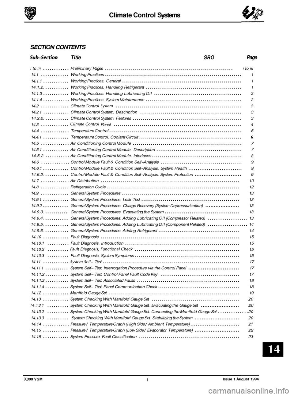
SECTION CONTENTS
Subsection Title SRO Page
i to iii ............ Preliminary Pages ................................................................ i to iii
14.1
............. Working Practices .................................................................... 1
Working Practices. General ............................................................ 1 14.1.1 ............
14.1.2. ........... Working Practices. Handling Refrigerant ................................................. 1
14.1.3 ............ Working Practices. Handling Lubricating Oil ............................................. 2
14.1.4
............ Working Practices. System Maintenance ................................................. 2
14.2
............. Climate ControlSystem ............................................................... 3
14.2.1
............ Climate Control System. Description .................................................... 3
14.2.2.
........... Climate Control System. Features ....................................................... 3
14.3
............. ClimateControl Panel ................................................................ 4
14.4
.............
14.4.1 ............ Temperature Control. Coolant Circuit .................................................... 6
14.5 ............. Air Conditioning Control Module ....................................................... 7
14.5.1 ............ Air Conditioning Control Module. Description 7
14.5.2. ........... Air Conditioning Control Module. Interfaces .............................................. 8
14.6
............. Control Module Fault & Condition Self-Analysis .......................................... 9
14.6.1
............ Control Module Fault & Condition Self-Analysis. System Health ............................. 9
14.6.2.
........... Control Module Fault & Condition Self-Analysis. System Protection .......................... 9
14.7
............. Air Distribution ..................................................................... 10
14.8
............. Refrigeration Cycle .................................................................. 12
14.9
............. General System Procedures ........................................................... 13
14.9.1
............ General System Procedures. Leak Test .................................................. 13
14.9.2
............ General System Procedures. Charge Recovery (System Depressurization) .................... 13
14.9.3.
........... General System Procedures. Evacuating the System ....................................... 13
14.9.4.
........... General System Procedures. Adding Lubricating Oil (Compressor Related) ................... 13
14.9.5.
........... General System Procedures. Adding Lubricating Oil (Component Related) ................... 14
14.9.6.
........... General System Procedures. Adding Refrigerant .......................................... 14
14.10
............ Fault Diagnosis ..................................................................... 15
14.10.1
.......... Fault Diagnosis. Introduction .......................................................... 15
14.10.2
.......... FaultDiagnosis. FunctionalCheck ..................................................... 15
14.10.3
14.11
............ Systemself- Test .................................................................... 17
14.1 1.1 ........... System Self- Test. Interrogation Procedure via the Control Panel ............................ 17
14.1 1.2 ........... System Self- Test. Control Panel Fault Code Key ......................................... 17
14.1 1.4 ........... System Self- Test. Panel Communication Check .......................................... 18
14.13
............ System Checking With Manifold Gauge Set ............................................. 20
14.7 3.1 .......... System Checking With Manifold Gauge Set. Evacuating the Gauge Set ...................... 20
14.13.2 .......... System Checking With Manifold Gauge Set. Connecting the Manifold Gauge Set .............. 20
14.13.3
.......... System Checking With Manifold Gauge Set. Stabilizing the System ......................... 20
14.14
............ Pressure / Temperature Graph (High Side / Ambient Temperature) ........................... 21
14.15
............ Pressure / Temperature Graph (Low Side / Evaporator Temperature) ......................... 22
14.16
............ System Pressure Fault Classification ................................................... 23
Temperature
Control
.................................................................. 6
............................................ a
.......... Fault Diagnosis. System Symptoms ..................................................... 15 a
14.1 1.3 ........... System Self- Test. Associated Faults .................................................... 18
14.12
............ Manifold Gauge Set ................................................................. 19
X300 VSM ~ i Issue 1 August 1994
Page 316 of 521

Climate Control Systems
CL /MATE CONTROL SYSTEM 0 14*2 14.2.1 Description
The climate control system in the 1995 model year saloon has a centre mounted heater / cooler unit with separate
blower assemblies, one LH and one RH. Heating temperature control is effected by means of a coolant flow valve and
circulation pump.
For models fitted with air conditioning, cooling is provide by passing air through the evaporator, which is situated im
- mediately behind the heater / cooler case inlet ducts.
Electric motors with integral potentiometers are used to position
all flaps.
W: There are no vacuum operated components in the system.
14.2.2 Features
o Self diagnostic control system with error codes.
0 Actuator 'self check'.
0 Display element check.
m: These features will be helpful for initial trouble shooting and where Jaguar Diagnostic Equipment (JDE) is not
available.
0 'Soft touch' logic controls. 0
0 Serial link from panel to control module (NCCM).
0 LCD display for temperature, status and fan speed.
0 Variable fan speed, whether in automatic or manual mode.
0 Manual air flow distribution over-rides.
0 Compensated air flow with regard to vehicle speed.
0 Rear footwell outlets.
0 Rear face outlets.
0 Scavenge system closed circuit temperature control.
0 Heated front screen (where fitted).
x300 VSM 3
Page 319 of 521

Climate Control Systems
14.4 TEMPERATURE CONTROL
14.4.1 Coolant Circuit
The main coolant system supplies liquid at engine temperature to the heater matrix to provide heat to the vehicle
interior. Unlike previous air blend / constant matrix temperature systems, in-car temperature is now controlled by
mixing recirculated coolant in the heater circuit with engine-temperature coolant. Matrix temperature is controlled
by a valve which opens to raise temperature (admit engine coolant) and closes to reduce it (recirculates coolant within
the circuit). The coolant flow valve operates on a six (6) second 'duty cycle', during which it may be open for whatever
period thecontrol system dictates. FACEvent airtemperature of howeveriscontrolled bythe'cool air by-passdamper'
which allows incoming air to flow around the top of the the heater matrix and thus remain unheated.
Because the engine coolant pump is driven proportionally to engine speed, the coolant delivery rate changes with
engine revolutions thus causing temperature variations. To stabilize the flow through the matrix, and thus the
temperature, an electrically driven circulation pump has been introduced into the system.
1
1. Engine 2. Coolant flow valve 3. Circulation pump
4. Heater matrix
5. Bottom hose
6. Engine cooling system radiator
Fig.
1 Coolant circuit, schematic view
Issue 1 August 1994 6 X300 VSM
Page 320 of 521

Climate Control Systems
Manual Inputs
Automatic inputs
outputs
14.5 AIR CONDITIONING CONTROL MODULE (A/CCM)
14.5.1 Description
Theclimate control system peripheralscommunicate with theA/CCMvia three main devicecategories, plusthevehicle
power supply and ground connections.
Control panel Face Vent Temperature Control
Temperature and solar sensors
Flap
servo motor potentiometers
Circulation pump
& coolant flow valve
Power
transistor(fan speed control)
Compressor lock sensor
(12 cylinder only)
Instrument pack (coolant temp
& road speed) (engine revolutions via engine control module)
Blower motors (Left
& Right) & associated relays
Flap
servo motors
Heated front
/ rear screens & exterior mirror relays
Motorized in
-car aspirator
Compressor clutch request to engine control module (not
heater-only cars)
Circulation pump relay
Coolant flow valve
X300 VSM Issue 1 August 1994 7
Page 321 of 521

Climate Control Systems
. Centre vent flap
Foot flap
Defrost flap
I I
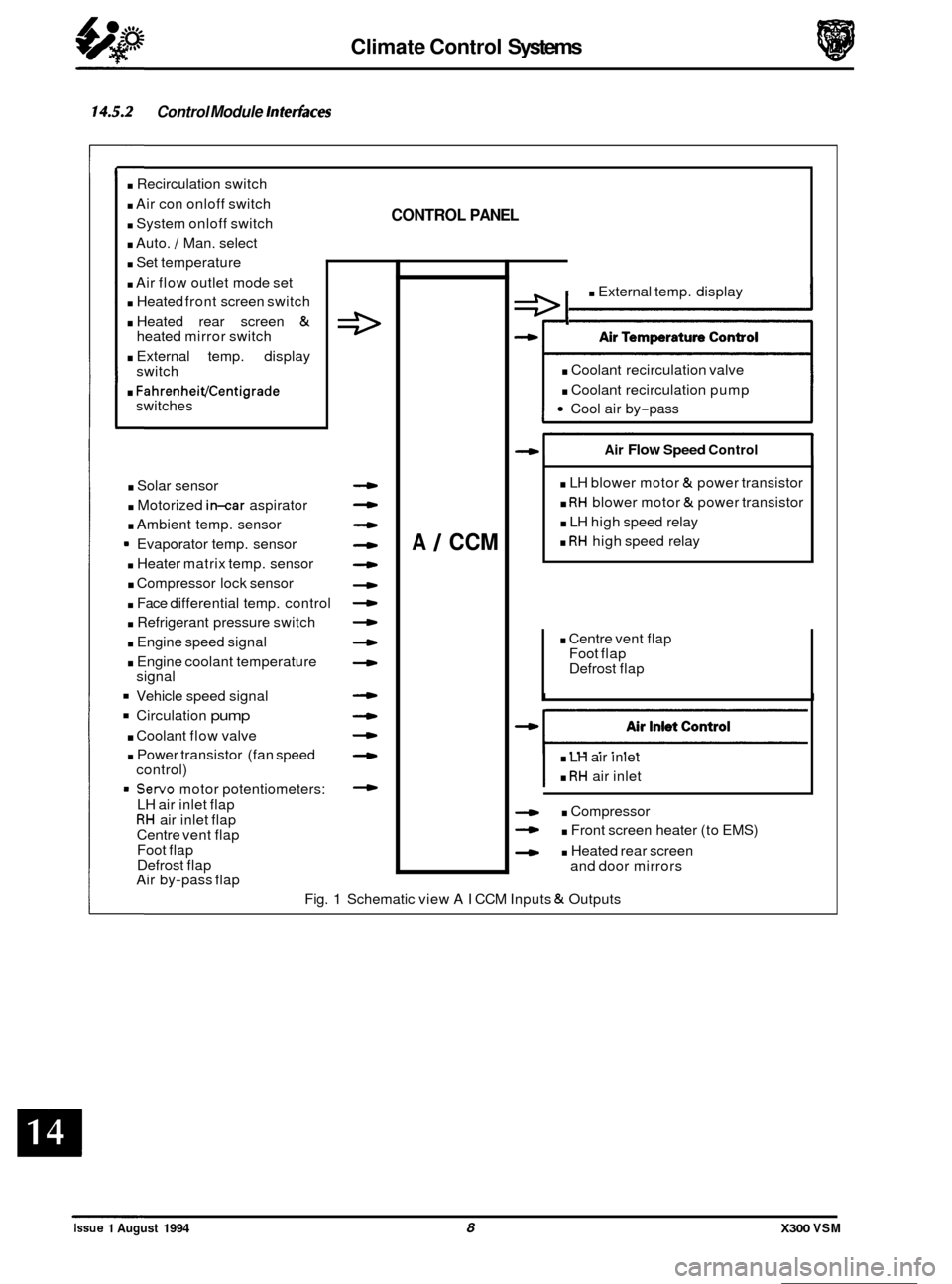
14.5.2 Control Module Interfaces
. Recirculation switch
. Air con onloff switch
. System onloff switch
. Auto. / Man. select
. Set temperature
. Air flow outlet mode set
. Heated front screen switch
. Heated rear screen &
. External temp. display
. FahrenheiVCentigrade
heated mirror switch
switch
switches
. Solar sensor
. Motorized in-car aspirator
. Ambient temp. sensor
9 Evaporator temp. sensor
. Heater matrix temp. sensor
. Compressor lock sensor
. Face differential temp. control
. Refrigerant pressure switch
. Engine speed signal
. Engine coolant temperature
Vehicle speed signal
Circulation pump
. Coolant flow valve
. Power transistor (fan speed
= Servo motor potentiometers:
signal
control)
LH air inlet flap
RH air inlet flap
Centre vent flap
Foot flap
Defrost flap
Air by
-pass flap
CONTROL PANEL
4
-
4
4
4
4
4
4
A 1 CCM
e I . External temp. display
. Coolant recirculation valve
. Coolant recirculation pump
Cool air by-pass
Air Flow Speed Control
. LH blower motor & power transistor
. RH blower motor & power transistor
. LH high speed relay
. RH high speed relay
. LH air inlet
. RH air inlet
. Compressor
- . Front screen heater (to EMS)
- . Heated rear screen
and door mirrors
Fig.
1 Schematic view AI CCM Inputs & Outputs
0
0
0
0
Issue 1 August 1994 8 X300 VSM