1994 JAGUAR XJ6 manual transmission
[x] Cancel search: manual transmissionPage 30 of 521

.
e
SECTION CONTENTS
Sub-section Title
i ................ Preliminary Page ............................................
2.1 .............. Jacking And Lifting ...........................................
2.1.1 ............. Jacking And Lifting. Safety Precautions ..........................
2.1.2 ............. Jacking And Lifting. Jacking Points ..............................
2.1.3 ............. Jacking And Lifting. Wheel Free Lift .............................
2.1.4 ............. Jacking And Lifting. Workshop Jacks ............................
2.1.4.1 ........... Jacking And Lifting. Workshop Jacks. Front - One Wheel ...........
2.1.4.2 ........... Jacking And Lifting. Workshop lacks. Front - Both Wheels ..........
2.1.4.3 ........... Jacking And Lifting. Workshop Jacks. Rear - Both Wheels ...........
2.2 .............. Vehicle Recovery ............................................
2.2.1. ............ Vehicle Recovery, General .....................................
2.2.2 .............
2.2.3 ............. Vehicle Recovery, Gear-shift Interlock - Manual Override .........
2.2.4 ............. Vehicle Recovery, Transporting .................................
2.2.5 ............. Vehicle Recovery, Towing Recovery .............................
2.2.6 ............. Vehicle Recovery, Vehicles With Defective Automatic Transmission ..
2.2.7. ............ Vehicle Recovery, Suspended Towing ...........................
2.2.8. ............ Vehicle Recovery, Rear Suspended Tow ..........................
Vehicle Recovery, Gear-shift Interlock ..........................
..
..
..
..
..
..
..
..
..
..
..
..
..
..
..
..
..
..
X300 VSM i
SRO
......
......
......
......
......
......
......
......
......
......
......
......
......
......
......
......
......
......
.
......
......
......
......
......
......
......
......
......
......
......
......
......
......
......
......
......
......
......
......
......
......
......
......
......
......
......
......
......
......
......
......
......
......
......
......
. Issue 1
Page
.... i
.... i
.... 1
.... 1
.... 1
.... 2
.... 2
.... 2
.... 2
.... 3
.... 3
.... 3
.... 3
.... 4
.... 4
.... 4
.... 5
.... 5
August 1994
Page 42 of 521

3.1.1 ENGINE, GENERAL
The 3.2 /4,0 liter normallv aspirated
and the 4.0
Engine (AJ16)
liter supercharged engined vehicles are equipped with the AJ 16family of six cylinder in-line engines. The engines have a fully mapped engine management system with digital ignition and
individual on-plug ignition coils.
This section describes the service procedures to be carried out with the engine in situ.
It also covers the renewal of the engine / transmission unit.
For information relating to strip
-down, inspection, fault diagnosis, renovation and rebuild work, refer to the AJ16
Engine Service Manual.
X300 VSM 1 Issue 1 August 1994
Page 48 of 521

Engine (V12)
3.2.1 ENGINE, GENERAL
The twelve cylinder, vee formation engine has a capacity of 6.0 liters. Each cylinder bank has a single overhead
camshaft and two valves percylinder. The engine has a fully mapped engine management system with digital ignition
and two ignition coils.
This section describes the service procedures to be carried out with the engine in situ.
It also covers the renewal of
the engine / transmission unit.
For information relating
tostrip-down, inspedion,fault diagnosis, renovation and rebuild work, referto the VI2 Engine
Service Manual.
X300 VSM 1 Issue 1 August 1994
Page 49 of 521

3.2.2 ENGINE - GEARBOX/ TRANSMISSION
ASSEMBLY, RENEW
SRO 12.37.01/90
The engine /transmission unit on the V12 6.0 liter model is mounted on three engine mounting / bracket assemblies
fitted to the front crossmember on either side of the engine bay. The engine/ transmission rear mount is a mounting
bracket and spring assembly fitted and secured to body underframe longitudinal members. For access to remove the
engine carry
out the following procedures:
WARNING: WHEN WORKING WITHIN THE ENGINE COMPARTMENT, KEEP CLEAR OF THE RADIATOR COOLING
FANS AS THEY COULD START WITHOUT WARNING, EVEN IF THE ENGINE IS NOT RUNNING.
. Remove the hood, see SRO 76.16.01, section 13.
. Remove the two air cleaner assemblies, see SRO’s 19.10.01 & 19.10.02.
. Remove the engine cover, see SRO 12.29.93 (V12 Engine Service Manual).
Depressurize the fuel system, see SRO 19.50.02, section 5.1.
In line with the relevant SRO’s and sections, remove all appropriate obstructing parts, including their fixing and
. Disconnect all mechanical and isolate all electrical linkages leading to and from the engine.
. De-gas the air conditioning system, see section 14, Charge Recovery (System depressurization).
Disconnect
the battery.
mounting arrangements.
CAUTION: Do
not vent refrigerant directly to the atmosphere and always use Jaguar approved recovery/recycle/ra charge equipment.
Drain the engine oil, see 3.2.3 this section.
Drain the coolant, see SRO 26.10.01, section 4.1.
WARNING: DO NOT REMOVE THE HEADER TANK PRESSURE CAP WHILE THE ENGINE IS HOT. IF THE CAP MUST
BE REMOVED, PROTECT THE HANDS AGAINST ESCAPING STEAM AND SLOWLY TURN THE CAP ANTI- CLOCKWISE UNTIL THE EXCESS PRESSURE CAN ESCAPE. LEAVE THE CAP IN THIS POSITION UNTIL ALL
STEAM AND PRESSURE HAS ESCAPED AND THEN REMOVE THE CAP COMPLETELY.
Before
lifting the complete engine/transmission unit with an engine hoist from the engine bay, ensure that two engine
lifting brackets (tool 18G. 1465) are secured equallyspaced to the inlet manifold studs. The four engine lifting brackets
should be positioned towards the front and the rear of the assembly. Ensure the front of thevehicle is jacked
up secure- ly on stands when removing the assembly.
X300 VSM Issue 1 August 1994 2
Page 114 of 521

Manual Transmission & Clutch (AJ16)
SECTlON CONTENTS
Sub-section Title SRO Page
i to iv ............ Preliminary Pages ................................................................ i to iii
7.1.1 ............. Manual Transmission. Description ...................................................... 1
7.1.2 ............. Manual Transmission Assembly, Renew ............................ 37.20.0 1 ............. 2
7.1.3
............. Front OilSeal. Renew .......................................... 37.23.06 ............. 5
7.1.4
............. Rear OilSeal. Renew ........................................... 37.23.01 ............. 6
7.1.5 ............. Gearshift Lever, Renew ......................................... 37.16.04 ............. 6
7.1.6 ............. Gearshift Lever Draught Excluder, Renew ......................... 37.16.05 ............. 6
7.1.7. ............ Gearshift Lever Knob. Renew .................................... 37.16.11 ............. 7
7.1.8. ............ Gearshifi Lever/ Remote Control Assembly, Renew .................. 37.16.20 ............. 7
7.1.9 ............. Gear Selector Shaft - Rear, Overhaul .............................. 37.16.4 1 ............. 9
7.1.10.
........... Reverse Lamp Switch. Renew .................................... 37.27.01 ............. 9
7.1.11 ............ Layshaft Front Seal. Renew ...................................... 37.23.07 ............. 9
7.1.12.
........... Clutch. Description .................................................................. 10
7.1.14.
........... Clutch Assembly, Renew ........................................ 33.10.01 ............ 14
7.1.15. ........... Clutch Master Cylinder, Renew .................................. 33.20.01 ............ 76
7.1.16. ........... Clutch Slave Cylinder, Renew ................................... 33.35.01 ............ 17
7.1.17.
........... Clutch Slave Cylinder, Overhaul ................................. 33.35.07 ............ 17
7.1.18. ........... Clutch Hydraulic System. Bleed .................................. 33.15.01 ............ 18
7 . 1 . 7 3 ............ Clutch. Fault Diagnosis .............................................................. 11
X300 VSM i Issue 1 August 1994
Page 116 of 521

Manual Transmission & clutch (AJ16)
I Molykote FB 180 grease
Brake (clutch) fluid
- minimum
DOT 4
Dexron IID Transmission oil
Loctite
573
Tivoli Kay Adhesives No. 5696
Withdrawal arm pivots / Gearshift lever ball
Clutch hydraulic system
Front cover securing bolts
Exhaust sealer also used
in
ZF automatic
transmissions
Application
Material removal to clean up clutch face
IU SERVICE DATA
Specification
Up to lmm maximum
X300 VSM iii Issue 1 August 1994
Page 118 of 521

Manual Transmission & Clutch (AJ16)
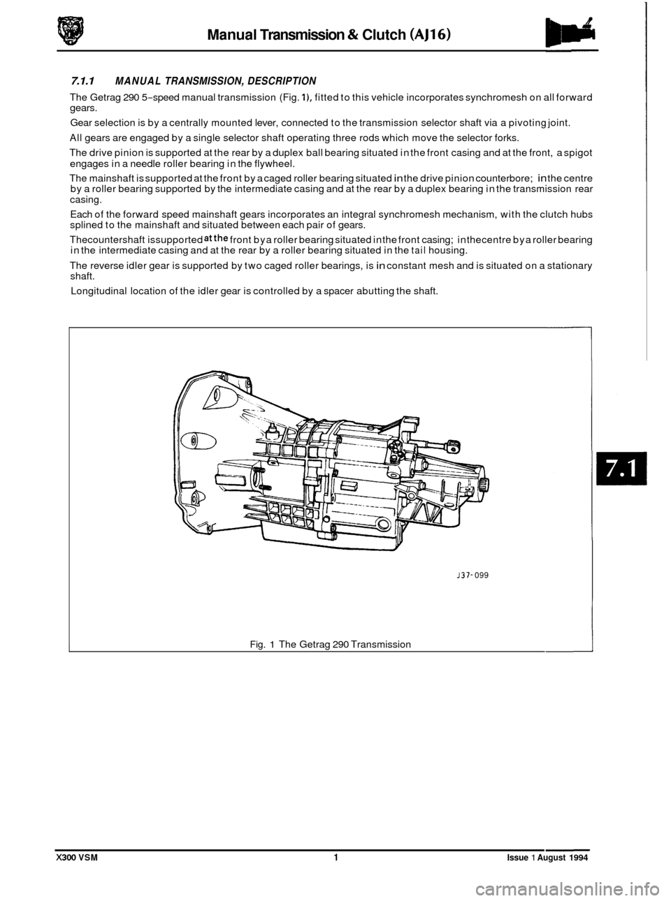
7.1.1 MANUAL TRANSMISSION, DESCRIPTION
The Getrag 290 5-speed manual transmission (Fig. I), fitted to this vehicle incorporates synchromesh on all forward
gears.
Gear selection is by a centrally mounted lever, connected to the transmission selector shaft via a pivoting joint.
All gears are engaged by a single selector shaft operating three rods which move the selector forks.
The drive pinion is supported at the rear by a duplex ball bearing situated in the front casing and at the front, a spigot
engages in a needle roller bearing in the flywheel.
The mainshaft is supported at the front by a caged roller bearing situated
in the drive pinion counterbore; in the centre
by a roller bearing supported by the intermediate casing and at the rear by a duplex bearing in the transmission rear
casing.
Each of the forward speed mainshaft gears incorporates an integral synchromesh mechanism, with the clutch hubs
splined to the mainshaft and situated between each pair of gears.
Thecountershaft issupported
atthe front bya roller bearing situated in the front casing; in thecentre bya roller bearing
in the intermediate casing and at the rear by a roller bearing situated in the tail housing.
The reverse idler gear is supported by two caged roller bearings, is
in constant mesh and is situated on a stationary
shaft.
Longitudinal location of the idler gear is controlled by a spacer abutting the shaft.
J37- 099
Fig. 1 The Getrag 290 Transmission
X300 VSM 1 Issue 1 August 1994
Page 119 of 521

Manual Transmission & Clutch (AJ16)
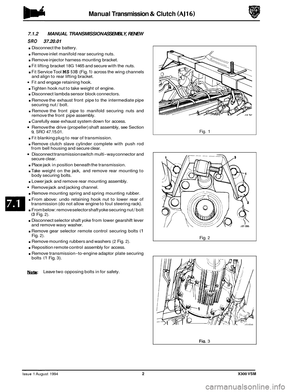
7.1.2 MANUAL TRANSMISSION ASSEMBLY, RENEW
SRO 37.20.01
. Disconnect the battery.
. Remove inlet manifold rear securing nuts.
. Remove injector harness mounting bracket.
. Fit lifting bracket 18G 1465 and secure with the nuts.
. Fit Service Tool MS 536 (Fig. 1) across the wing channels
Fit and engage retaining hook.
. Tighten hook nut to take weight of engine.
. Disconnect lambda sensor block connectors.
. Remove the exhaust front pipe to the intermediate pipe
securing nut / bolt.
. Remove the front pipe to manifold securing nuts and
remove the front pipe assembly.
. Carefully ease exhaust system down for access.
Remove the drive (propeller) shaft assembly, see Section
. Fit blanking plug to rear of transmission.
. Remove clutch slave cylinder complete with push rod
Disconnect transmission switch multi-way connector and
. Place jack in position beneath the transmission.
. Take weight on the jack, and remove rear mounting to
. Lower jack and remove rear mounting assembly.
Remove jack and jacking channel.
. Remove mounting spring and spring mounting rubber.
. From above: undo retaining hook nut to lower rear of
transmission (do not allow engine to foul steering rack).
. From below: remove selector shaft yoke securing nut / bolt (3 Fig. 2).
. Disconnect selector shaft yoke from lower gearshift lever
and remove wavy washer.
. Remove gear selector remote control securing bolts (1 Fig. 2).
. Remove mounting rubbers and washers (2 Fig. 2).
. Reposition remote control assembly for access.
. Remove transmission-to-engine adaptor plate securing
and
align to rear lifting bracket.
9, SRO 47.15.01.
from bell housing and secure clear.
secure clear.
body securing bolts.
bolts
(1 Fig. 3).
N.&: Leave two opposing bolts in for safety.
Fig. 1
Fig.
2
Fig. 3 ~ ~ ~~ ~
Issue 1 August 1994 2 X300 VSM