1994 JAGUAR XJ6 maintenance
[x] Cancel search: maintenancePage 310 of 521

Climate Control Systems
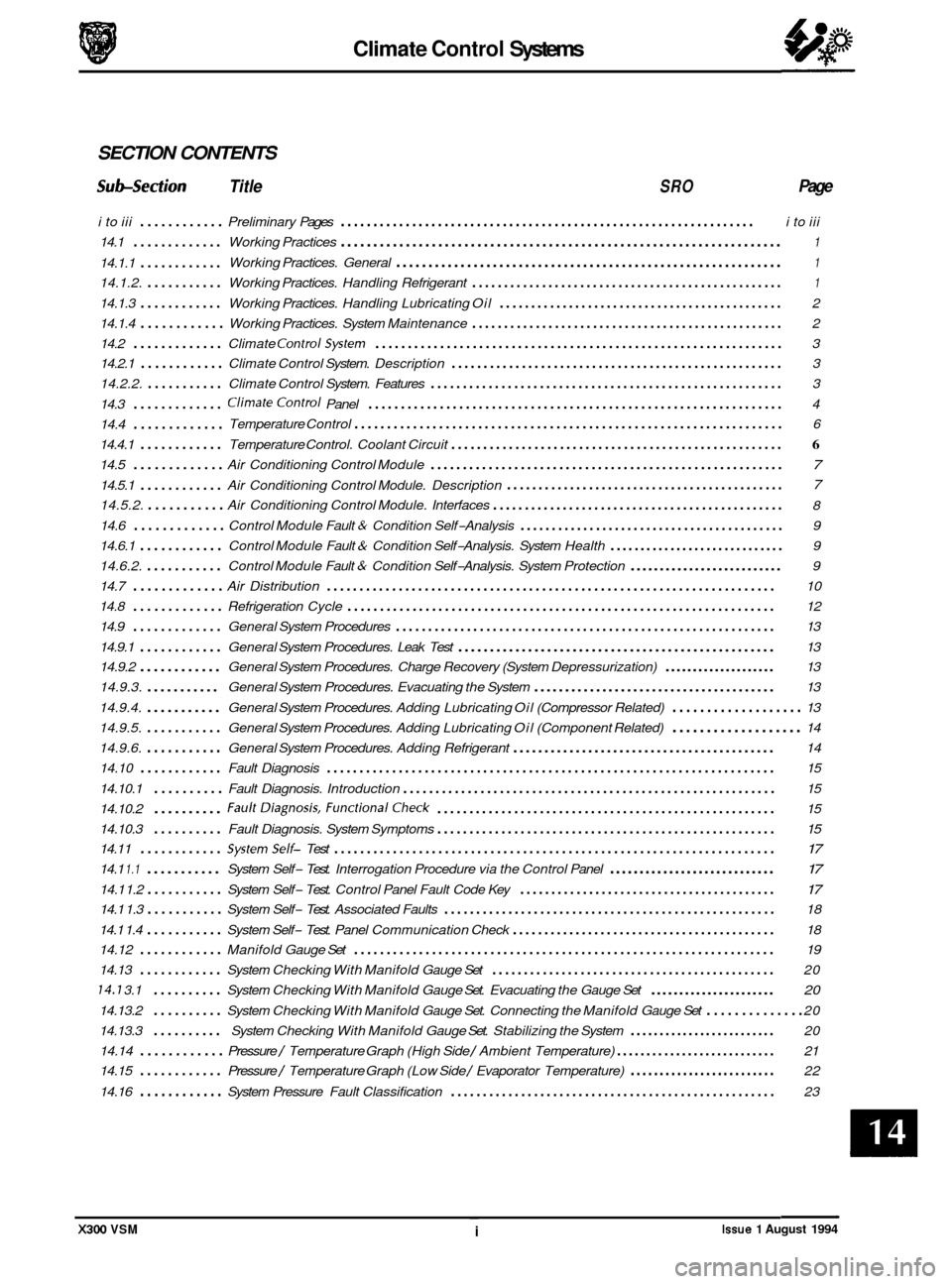
SECTION CONTENTS
Subsection Title SRO Page
i to iii ............ Preliminary Pages ................................................................ i to iii
14.1
............. Working Practices .................................................................... 1
Working Practices. General ............................................................ 1 14.1.1 ............
14.1.2. ........... Working Practices. Handling Refrigerant ................................................. 1
14.1.3 ............ Working Practices. Handling Lubricating Oil ............................................. 2
14.1.4
............ Working Practices. System Maintenance ................................................. 2
14.2
............. Climate ControlSystem ............................................................... 3
14.2.1
............ Climate Control System. Description .................................................... 3
14.2.2.
........... Climate Control System. Features ....................................................... 3
14.3
............. ClimateControl Panel ................................................................ 4
14.4
.............
14.4.1 ............ Temperature Control. Coolant Circuit .................................................... 6
14.5 ............. Air Conditioning Control Module ....................................................... 7
14.5.1 ............ Air Conditioning Control Module. Description 7
14.5.2. ........... Air Conditioning Control Module. Interfaces .............................................. 8
14.6
............. Control Module Fault & Condition Self-Analysis .......................................... 9
14.6.1
............ Control Module Fault & Condition Self-Analysis. System Health ............................. 9
14.6.2.
........... Control Module Fault & Condition Self-Analysis. System Protection .......................... 9
14.7
............. Air Distribution ..................................................................... 10
14.8
............. Refrigeration Cycle .................................................................. 12
14.9
............. General System Procedures ........................................................... 13
14.9.1
............ General System Procedures. Leak Test .................................................. 13
14.9.2
............ General System Procedures. Charge Recovery (System Depressurization) .................... 13
14.9.3.
........... General System Procedures. Evacuating the System ....................................... 13
14.9.4.
........... General System Procedures. Adding Lubricating Oil (Compressor Related) ................... 13
14.9.5.
........... General System Procedures. Adding Lubricating Oil (Component Related) ................... 14
14.9.6.
........... General System Procedures. Adding Refrigerant .......................................... 14
14.10
............ Fault Diagnosis ..................................................................... 15
14.10.1
.......... Fault Diagnosis. Introduction .......................................................... 15
14.10.2
.......... FaultDiagnosis. FunctionalCheck ..................................................... 15
14.10.3
14.11
............ Systemself- Test .................................................................... 17
14.1 1.1 ........... System Self- Test. Interrogation Procedure via the Control Panel ............................ 17
14.1 1.2 ........... System Self- Test. Control Panel Fault Code Key ......................................... 17
14.1 1.4 ........... System Self- Test. Panel Communication Check .......................................... 18
14.13
............ System Checking With Manifold Gauge Set ............................................. 20
14.7 3.1 .......... System Checking With Manifold Gauge Set. Evacuating the Gauge Set ...................... 20
14.13.2 .......... System Checking With Manifold Gauge Set. Connecting the Manifold Gauge Set .............. 20
14.13.3
.......... System Checking With Manifold Gauge Set. Stabilizing the System ......................... 20
14.14
............ Pressure / Temperature Graph (High Side / Ambient Temperature) ........................... 21
14.15
............ Pressure / Temperature Graph (Low Side / Evaporator Temperature) ......................... 22
14.16
............ System Pressure Fault Classification ................................................... 23
Temperature
Control
.................................................................. 6
............................................ a
.......... Fault Diagnosis. System Symptoms ..................................................... 15 a
14.1 1.3 ........... System Self- Test. Associated Faults .................................................... 18
14.12
............ Manifold Gauge Set ................................................................. 19
X300 VSM ~ i Issue 1 August 1994
Page 315 of 521

Climate Control Systems
0 Because HFC 134A is fully recycleable it may be 'cleaned' by the recovery equipment and re-used following
removal from a system.
0 Leak tests should only be carried out with an electronic analyzer which is dedicated to HFC 134A. Never use a CFC 12 analyzer or naked flame type.
0 Do not attempt to 'guess' the amount of refrigerant in a system, always recover and recharge with the correct
charge weight. In this context do not depress the charge or discharge port valves to check for the presence of
refrigerant.
14.1.3 Handling Lubricating Oil
0 Avoid breathing lubricant mist, it may cause irritation to your respiratory system.
0 Always decant fresh oil from a sealed container and do not leave oil exposed to the atmosphere for any reason
other than to fill or empty a system. PAG oil is very hygroscopic (absorbs water) and will rapidly become con-
taminated by atmospheric moisture.
PAG oil is
NOTcompatible with previously used mineral based oils and must NEVER be mixed (Fig. 1). Do not
re
-use oil when it has been separated from refrigerant, following a recovery cycle. Dispose of used oil safely.
14.1.4 System Maintenance
0 When depressurizing a system do not vent
refrigerant directlyto atmosphere, always use Jaguar
approved recovery equipment.
0 Always decant compressor oil from a sealed con- tainer and do not leave oil exposed to the atmosphere
for any reason other than to fill or empty
a system.
PAG oil is very hygroscopic and will rapidly become
contaminated by atmospheric moisture.
0 Plug pipes and units immediately after disconnection
and only unplug immediately priorto connection. Do
not leave the system open to atmosphere.
0 It is not necessary to renew the receiver drier when- ever the system has been 'opened' as previously ad-
vised - see note this page. However,if a unit or part
of the system is left open for more than five minutes,
it may be advisable to renew the receiver drier. This
guidance is based on
U.K average humidity levels;
therefore, locations with lower humidity will be less
critical to moisturecontamination of the unit.
It must
be stressed that there is not
a 'safe' period for workto
be carried out in: ALWAYS plug pipes and units im-
mediately after disconnection and only remove plugs
immediately prior to connection.
J82-387
Fin. 1
U: The receiver / drier MUST be renewed if the compressor has failed or if it is suspected that debris may be in
the system.
0 If replacement parts are supplied without transit plugs and seals DO NOT use the parts. Return them to your
supplier.
0 Diagnostic equipment for pressure, mass and volume should be calibrated regularly and certified by a third
party organization.
0 Use extreme care when handling and securing aluminium fittings, always use a backing spanner and take
special care when handling the evaporator.
0 Use only the correct or recommended tools for the job and apply the manufacturer's torque specifications.
Issue 1 August 1994 2 X300 VSM
Page 402 of 521

Routine Maintenance
CON TENTS
Title
Routine Maintenance, 1995 Model Year Vehicles . . . . . . . . . . . . . . . . . . . . . . . . . . .
Fluids & Lubricants Service Points, 6 Cylinder Vehicles . . . . . . . . . . . . . . . . .
Fluids & Lubricants Service Points, 12 Cylinder Vehicles . . . . . . . . . . . . . . . .
Service Schedule, U.K., Europe, R.O. W. . . . . . . . . . . . . . . . . . . . . . . . . . . . . . .
Service Schedule, USA / Canada . . . . . . . . . . . . . . . . . . . . . . . . . . . . . . . . . . . .
....
....
....
....
....
-
...
...
...
...
..................
..................
..................
..................
..................
....
....
....
....
....
.... 7
.... 1
.... 2
.... 3
.... 5
Issue 1 August 1994 A2-95MY i X300 VSM
Page 405 of 521

2 4 11 87
* * Rout ine Maintenance
- X300 VSM
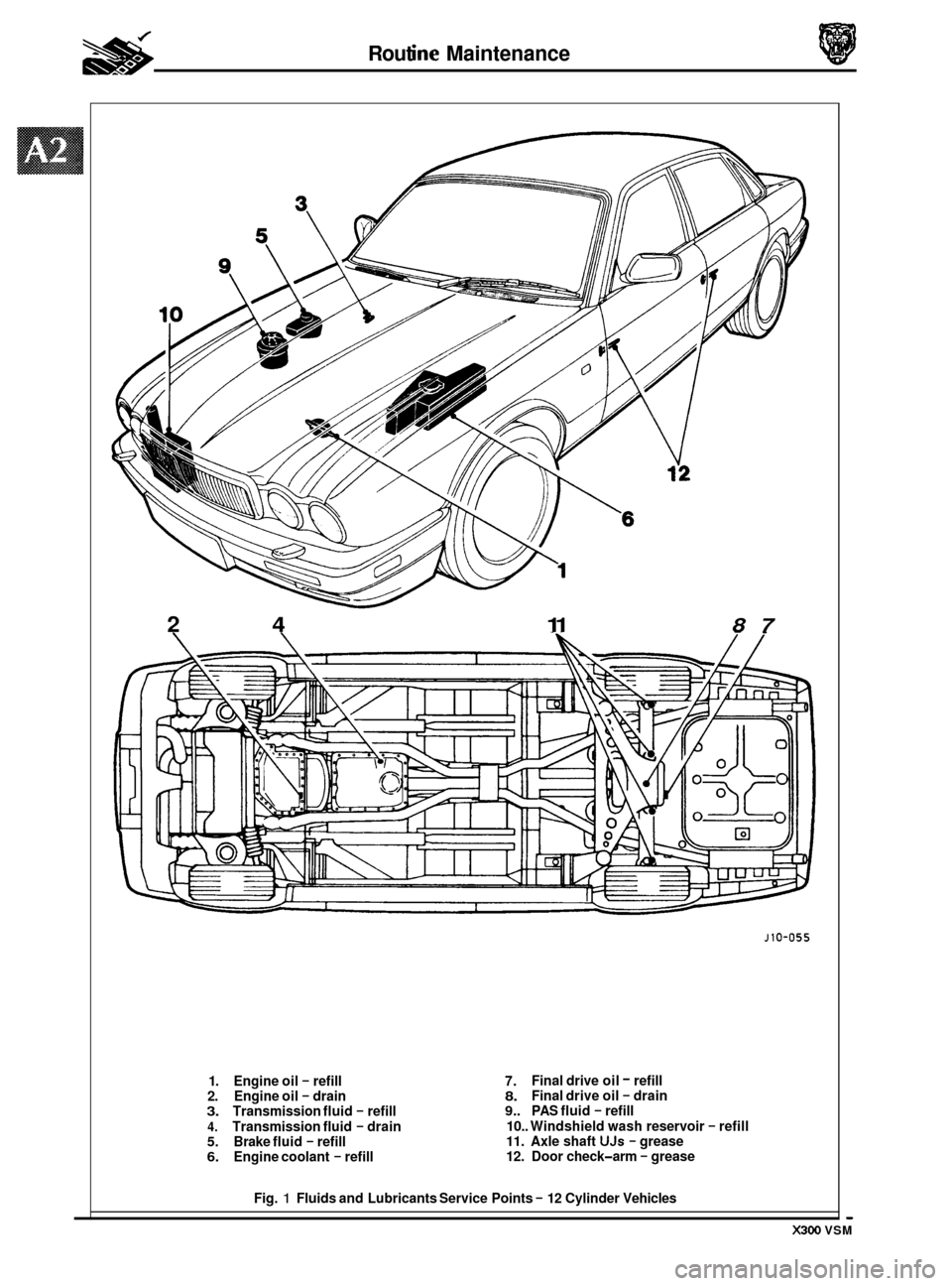
1. Engine oil - refill
2. Engine oil - drain 3. Transmission fluid - refill
4. Transmission fluid - drain 5. Brake fluid - refill 6. Engine coolant - refill
J10-055
7. 8. 9.. PAS fluid - refill
10.. Windshield wash reservoir
- refill 11. Axle shaft UJs - grease
12. Door check-arm - grease
Final drive
oil
- refill
Final drive oil - drain
Fig.
1 Fluids and Lubricants Service Points - 12 Cylinder Vehicles
Page 406 of 521

Routine Maintenance
SERVICE SCHEDULE - UK, EUROPe ROW
3.2 Liter, 4.0 Liter, 4.0 Liter SC and 6.0 Liter
0
0
Note: This note only applies to VI2 engines.
When renewing spark plugs, apply silicon grease
(TBA) to the spark plug and coil terminals of the ignition
cable. This will ensure that the terminal covers remain supple throughout their service life, thus maintaining
a good contact and preventing HT leakage.
A2-95MY 3 Issue 1 August 1994 X300 VSM
Page 407 of 521

* Routine Maintenance
Item Service intervals Miles (XlOOO)
10 20
35 Check power steering system for leaks and hydraulic X X
pipes 1 unions for chafing I corrosion
30 40 50 60
X X X X
X X X X
X X X X
X X
X X X
X
X X
X X X X
X
X X X
.
X300 VSM Issue 1 August 1994 A2-95MY 4
Page 409 of 521

Routine Maintenance
Service intervals
Check power steering system for leaks and hydraulic
pipes
/ unions for chafing /corrosion
Check Cooling
/ heating system for leaks / security
Check visually hydraulic hoses
/ pipes / unions for
leaks
/ chafing / cracks / corrosion
Check condition of steering rack joint covers
Check speed control vacuum hoses for security and
general condition
Grease door check
-arm side edges
Check parking brake cable adjustment
Miles (X 1000)
7.5 15
X X
xx
xx
xx
xx
X
xx
xxxxxx
xxxxxx
x
X X X
xxxxxx
X X X
xxxxxx
XIX x x x
-
Clean out radiator matrix and condenser (where fitted)
to remove dirt accumulation
Clean antenna mast
xx
Carry out road / roller test Ix
i
0
0
0
X
x
issue 1 August 1994 A2-95MY 6 X300 VSM