Page 387 of 521

Steering and Suspension
W: When checking the steering geometry, use the pull-down tools front and rear to set the ride height front and
rear to the following dimensions:
Front ride height
................................................... 153 f 5mm to underside of front
crossbeam
Rear ride height
.................................................... 160 f 5mm to underside of rear
edge of A frame
Front ride height
................................................... 143 f 5mm to underside of front
crossbeam
Rear ride height
.................................................... 160 f 5mm to underside of rear
edge of A frame
U: Sportspack derivatives whose kerb height is below the above figures can have their geometry checked at that
height.
Front Suspension
..............................................................
0
Type Independent front suspension
consisting of double wishbones
with coil springs and separate
dampers and anti
-roll bar.
Dampers
.......................................................... Telescopic, gas pressurised
Caster angle
....................................................... 3,0° to 6,0° and with opposing
wheels within Io of each other
Camberangle
...................................................... 0,3°to-0,80
Front wheel alignment .............................................. Total toe: 5 minutes in f 10 minutes
Rear Suspension
Type .............................................................. Fully independent rear suspension of double wishbone principle with
axle shaft operating as upper
wishbone incorporating coaxial
springs and dampers with optional
rear anti
-roll bar.
Camber angle
(at design ride height):
all vehicles except supercharged ................................. -0,75O f 0,4O
supercharged only -1,6O f 0,4O ..............................................
0 Rear wheel alignment .............................................. Total toe: 15 minutes in f20
Dampers .......................................................... Telescopic, gas pressurised
minutes
Power Assisted Steering
Type .............................................................. ZF
Servotronic speed-sensitive rack
and pinion
Number
of turns lock to lock ........................................ 2,768
Turning circle: (wall to wall)
....................................................... 12,9m (42ft 4in)
(curb to curb) ...................................................... 12,4m (40ft 8in)
0
X300 VSM Issue 1 August 1994 AI-95MY 4 ~~~~
Page 436 of 521

Body Systems
A4.2.1.1 Constructional Steel Classification
Material 1 dnnlirdiam I
High strength low alloy (HLSA).
Double sided zinc plated mild steel.
1 Boron steel
1 Mild steel.
A4.2.2 BODY ALIGNMENT
The illustrations on pages 11 - Body Dimensions PLAN, and 13 -Body Dimensions SIDE VIEW, provide specifications
for damage assessment and location of replacement parts.
These dimensions must be strictly applied whether they are used for damage assessment, component location or post
repair verification.
The plan view MASTER datums are nominated on the right
-hand side of the body with the left-hand datums dimen- sioned from them. Therefore, the right-hand datums must be known to be correct before any other cross-ar dimen- sions are checked.
W: The right-hand side is always looking towards the front, from the rear of the vehicle.
All dimensions are derived from a single
(ZERO) datum point for all three axes; X for length, Z for height and V cross- car.
Issue 1 August 1994 9 X300 VSM
A4.2 BODY STRUCTURE
A4.2.1
Introduction
The Jaguar sedan range (with standard wheelbase) has a unit construction monocoque body structure with bolt-on
front fenders and welded rear fenders. The doors feature 'lift-off' hinges and welded dropglass frames.
n@#pn.s..v..
Impact prone areas, ie. seat frame and bumper mount- ings.
Exterior body panels subject to severe conditions such
as stone chipping and weather exposure (excluding
roof panel).
Door intrusion beams
Internal brackets, fillets and strengtheners.
I
Page 464 of 521
conditions.
. Tighten all fixings to specification.
A4.6.1.3 SERVICE PROCEDURES
A4.6.1.4
Fitted Condition (Front)
The following procedures may apply should any part of the bumper mounting system, or cover, be renewed but should
not be necessary if the cover is removed for service reasons.
The front mountings must initially be set for 'cross car' pitch and center within the clearances around thestrut to body
. In orderthat the bumpertop face, headlamp surrounds and grille lower have the correct relationship the strut height
. Set the guide blocksto thespecified dimensionto achievethecorrect bumpertofender gap, BEFOREfittingthecover
. With all fixing points set, the bumper cover may be fitted and adjusted as necessary to achieve the specified gap
fixings.
adjusters must be finally
set AFTER the cover is fitted.
because adjustments can only be made with the cover
off.
Fig. 1 Front bumper setting dimensions
Issue 1 August 1994 37 X300 VSM
Page 465 of 521

Body Systems & Body Repair
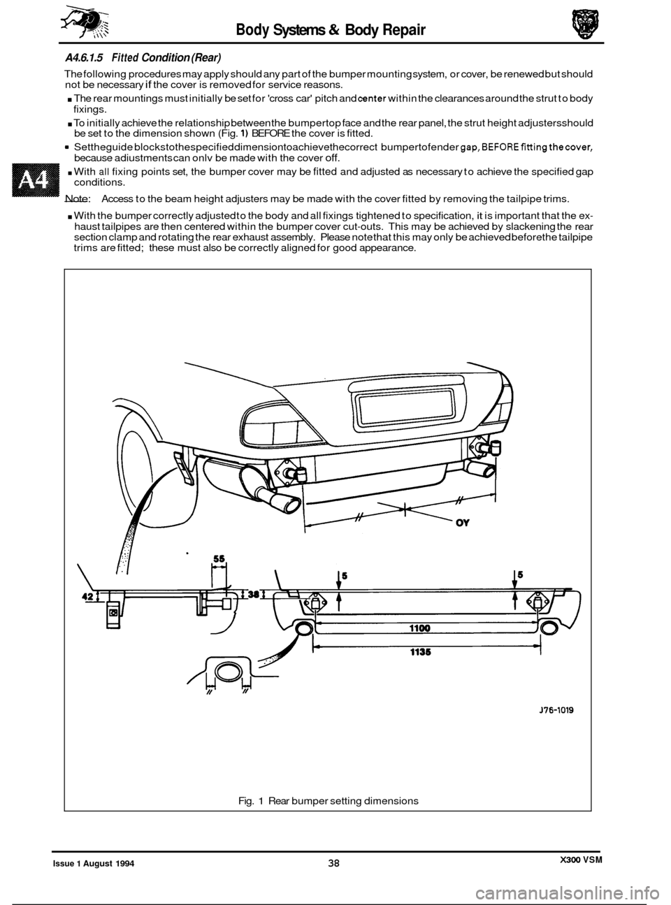
A4.6.1.5 Fitted Condition (Rear)
The following procedures may apply should any part of the bumper mounting system, or cover, be renewed but should
not be necessary if the cover is removed for service reasons.
. The rear mountings must initially be set for 'cross car' pitch and center within the clearances around the strut to body
. To initially achieve the relationship between the bumpertop face and the rear panel, the strut height adjustersshould
9 Settheguide blockstothespecified dimensiontoachievethecorrect bumpertofender gap,BEFOREfittingthecover,
fixings.
be set to the dimension shown (Fig.
1) BEFORE the cover is fitted.
because adiustments can onlv be made with the cover
off.
. With all fixing points set, the bumper cover may be fitted and adjusted as necessary to achieve the specified gap
- Note:
conditions.
Access to the beam height adjusters may be made with the cover fitted by removing the tailpipe trims.
. With the bumper correctly adjusted to the body and all fixings tightened to specification, it is important that the ex-
haust tailpipes are then centered within the bumper cover cut-outs. This may be achieved by slackening the rear
section clamp and rotating the rear exhaust assembly. Please note that this may only be achieved before the tailpipe
trims are fitted; these must also be correctly aligned for good appearance.
J76-1019
Fig. 1 Rear bumper setting dimensions
X300 VSM Issue 1 August 1994 38