1994 JAGUAR XJ6 fuel fil
[x] Cancel search: fuel filPage 92 of 521

striker and the fuel cap stowage magnet.
The fuel bowl, retained around the filler neck by a clip, containing a drain tube filter located
overthe mating drain tube,
is rubber moulded onto a steel armature and fitted to the BIW decking panel. by five M5 nuts.
The fuel lid latching assembly fitted to the metal armature of the fuel bowl by an M5 nut, includes the locking pin and
the operating actuator.
The actuator operates from the central locking system driven by the Security and Locking Control Module (SLCM).
The fuel tank, mounted across the vehicle behind the passenger compartment rear bulkhead, is held in position by two
retaining straps, tightened by two M5 fixing arrangements.
VI2 engined vehicles are equipped with two fuel pumps located inside the tank. They are regenerative turbine pumps
supplied by Nippon Denso. Nominal operating pressure is 3 bar above the manifold depression and pump delivery
is 90 litres/hour minimum at 13.2 volts, 3 bar outlet pressure. The pump draws a nominal current of 7 amperes at 13 volts, 3 bar outlet pressure, ambient temperatures. Built in to the pump assembly is a over-pressure relief valve which
blows at 4.5 - 8.5 bar.
Fuel is drawn by the pumps from the fuel tank and is then supplied to the fuel rail via a
70 micron filter and the fuel
feed line connected in series by fuel filter.
The amount of fuel being injected into the engine is controlled by the fuel injectors combined with the engine control
module (ECM).
Any excessive fuel flowing through the system, is returned to thefuel tankvia the fuel regulator valve mounted on the
fuel rail, the fuel return line and the check valve also located inside the tank.
The two filters prevent contaminants from entering the fuel rail and possible damage to the fuel injectors, the engine,
the pump and underfloor filter.
The second fuel pump is controlled by the engine control module
(ECM) and works of a mapped fuel map. The pumps
'switch on' time depends on the fuel requirement which is depending on the engine load.
The fuel lines are made up of an assembly, combining steel underfloor pipes and flexible conductive anti
-permeation
tubing. In order to perform speedy remove and refit operations, the underfloor steel lines are linked through the engine
bay bulkhead to theflexibletubing, leading to the fuel rail and the fuel regulator by using positive sealing, quick
fit type
connectors. The same type connectors, are used to connect the fuel feed and return line to the fuel tank.
Connectors used inside the engine bay, are of different sizes to correspond with the difference in pipe diameter, where
- as the connectors for the feed and return lines at the fuel tank are the same size.
Except for the return line connector at the fuel tank, two release tools, one for each size of connector, are required to
release all remaining connectors.
Fuel, Emission Control & Engine Management (V12)
5.2.2 GENERAL DESCRIPTION
WARNING: WORKING ON THE FUEL SYSTEM RESULTS IN FUEL AND FUEL VAPOUR BEING PRESENT IN THE AT- MOSPHERE. FUEL VAPOUR IS EXTREMELY FLAMMABLE, HENCE GREAT CARE MUST BE TAKEN WHILST
WORKING ON THE FUEL SYSTEM. ADHERE STRICTLY TO THE FOLLOWING PRECAUTIONS:
PO NOT SMOKF, IN THE WORK AREA.
DISPLAY 'NO SMOKING
' SIGNS AROUND THE AREA.
ENSURE THAT A
CO2 FIRE EXTINGUISHER IS CLOSE AT HAND.
ENSURE THAT DRY SAND
IS AVAILABLE TO SOAK UP ANY FUEL SPILLAGE.
EMPTY FUEL USING SUITABLE FIRE PROOF EQUIPMENT INTO AN AUTHORIZED EXPLOSION PROOF
CONTAINER.
DO NOT EMPTY FUEL INTO A PIT.
ENSURE THAT WORKING AREA IS WELL VENTILATED.
ENSURE THAT ANY WORK ON THE FUEL SYSTEM
IS ONLY CARRIED OUT BY EXPERIENCED AND WELL
QUALIFIED MAINTENANCE PERSONNEL.
The fuel filler assembly, supplied complete with serviceable lid, hinge and hinge spring, is fixed to the Body-in-White (BIW) decking panel by two M5 nuts. Additional parts of the assembly comprise a adjustable rubber buffer, a snap-in
X300 VSM 3 Issue 1 August 1994
Page 250 of 521

Body Components & Trim .
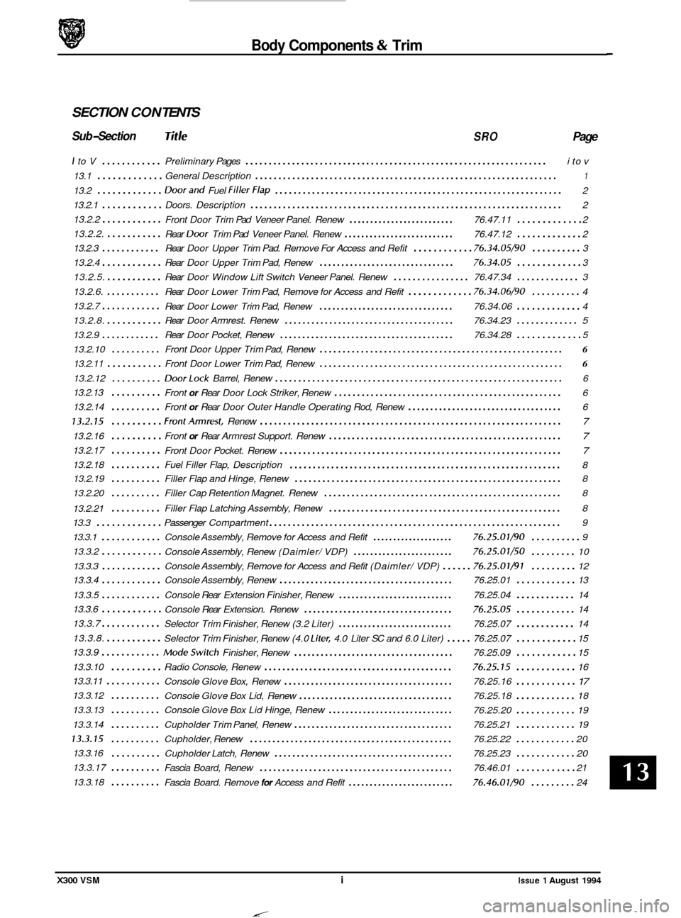
SECTION CON TENTS
Sub-Section Tit /e SRO Page
I to V ............ Preliminary Pages ................................................................. i to v
13.1
............. General Description ................................................................. 1
13.2 ............. Doorand Fuel FillerFlap .............................................................. 2
13.2.1
............ Doors. Description ................................................................... 2
13.2.2
............ Front Door Trim Pad Veneer Panel. Renew ......................... 76.47.11 ............. 2
13.2.2.
...........
13.2.3 ............ Rear Door Upper Trim Pad. Remove For Access and Refit ............ 76.34.05/90 .......... 3
13.2.5.
........... Rear Door Window Lift Switch Veneer Panel. Renew ................ 76.47.34 ............. 3
13.2.6.
........... Rear Door Lower Trim Pad, Remove for Access and Refit ............. 76.34.06/90 .......... 4
13.2.7
............ Rear Door Lower Trim Pad, Renew ............................... 76.34.06 ............. 4
13.2.8.
........... Rear Door Armrest. Renew ...................................... 76.34.23 ............. 5
13.2.9 ............ Rear Door Pocket, Renew ....................................... 76.34.28 ............. 5
13.2.10 .......... Front Door Upper Trim Pad, Renew ..................................................... 6
13.2.11 ........... Front Door Lower Trim Pad, Renew ..................................................... 6
13.2.12 .......... DoorLock Barrel, Renew .............................................................. 6
13.2.13 Front
or Rear Door Lock Striker, Renew .................................................. 6
13.2.14
.......... Front or Rear Door Outer Handle Operating Rod, Renew ................................... 6
13.2.15 .......... FrontArmrest, Renew ................................................................. 7
13.2.16 .......... Front or Rear Armrest Support. Renew ................................................... 7
13.2.17 .......... Front Door Pocket. Renew ............................................................. 7
........................................................... 8
Rear
Door Trim
Pad Veneer Panel. Renew .......................... 76.47.12 ............. 2
13.2.4
............ Rear Door Upper Trim Pad, Renew ............................... 76.34.05 ............. 3
..........
13.2.18 .......... Fuel Filler Flap, Description
13.2.19
.......... Filler Flap and Hinge, Renew .......................................................... 8
13.2.20
.......... Filler Cap Retention Magnet. Renew .................................................... 8
.......... Filler Flap Latching Assembly, Renew ................................................... 8
13.2.21
13.3
............. Passenger Compartment ............................................................... 9
13.3.1
............ Console Assembly, Remove for Access and Refit .................... 76.25.01/90 .......... 9
13.3.2
............ Console Assembly, Renew (Daimler/ VDP) ........................ 76.25.07/50 ......... 10
13.3.3
............ Console Assembly, Remove for Access and Refit (Daimler/ VDP) ...... 76.25.01/91 ......... 12
13.3.4
............ Console Assembly, Renew ....................................... 76.25.01 ............ 13
13.3.5
............ Console Rear Extension Finisher, Renew ........................... 76.25.04 14
Selector Trim Finisher, Renew (3.2 Liter)
........................... 76.25.07 ............ 14
Modeswitch Finisher, Renew .................................... 76.25.09 ............ 15
13.3.10
.......... Radio Console, Renew .......................................... 76.25.15 ............ 16
Console Glove Box, Renew
...................................... 76.25.16 ............ 17
Console Glove Box Lid, Renew ................................... 76.25.18 ............ 18
.......... Console Glove Box Lid Hinge, Renew ............................. 76.25.20 ............ 19
13.3.14
.......... Cupholder Trim Panel, Renew .................................... 76.25.21 ............ 19
13.3.15 .......... Cupholder, Renew ............................................. 76.25.22 ............ 20
.......... Cupholder Latch, Renew ........................................ 76.25.23 ............ 20
Fascia Board, Renew ........................................... 76.46.01 ............ 21
13.3.6
............ Console
Rear Extension. Renew .................................. 76.25.05 ............ 14
13.3.7
............
13.3.8. ........... Selector Trim Finisher, Renew (4.0 Liter, 4.0 Liter SC and 6.0 Liter) ..... 76.25.07 ............ 15
13.3.9
............
............
13.3.11 ...........
13.3.12
13.3.13 ..........
13.3.16
13.3.17
..........
13.3.18 .......... Fascia Board. Remove for Access and Refit ......................... 76.46.01/90 ......... 24
X300 VSM i Issue 1 August 1994
Page 256 of 521

Body Components & Trim
13.1 GENERAL DESCRIPTION
This section covers the following areas of the vehicle body:
0 Battery cover
0 Carpets - passenger compartment, trunk
0 Console - including radio, glovebox
0 Doors -frames, sealing, locks, trim, glazing
0 Fascia
0 Fuel filler flap assembly
0 Footrest
0 Hood - liners, gas strut, locking,
0 Illuminated sunvisor - inc mirror
0 Interior trim - trim pads, finishers, veneers
0 Mirrors - internal, external
0 Rear parcel tray
0 Roof console
0 Roof lining (headlining)
o Seats -front, rear -
0 Seat belts - front, rear
0 Sliding roof
0 Steering column cowl
0 Underscuttle pad
Refer to Appendix
A4 - Body Systems & Body Repair for information relating to crash-damage repairs and to the fol- lowing external components: exterior trim, bumpers, windscreen and rear screen, closures and sealing.
Refer to Section 15, Electrical for details of the following motors and solenoids: driver's and interior mirrors, window
lift, sunroof, seat / headrest and locking mechanisms (doors, trunk and filler cap).
Refer to Section 15, Electrical and Electrical Diagnostic Manual (EDM) for details of the passenger and driver airbags.
X300 VSM 1 Issue 1 August 1994
Page 257 of 521

Body Components & Trim d-!P
13.2
13.2.1 Doors, Description
Doors are of welded, mild steel frames welded to the door panels; sponge rubber primary and secondary seals are
mounted on the doors. Internal insulation is provided by a foam water shedder attached to the door by press fitting and doublesided adhesive tape.
Front and rear door armrests are attached to supports riveted to each door frame; the attaching screws are fitted
with access covers. Upper and lower trim pads and a door pocket are attached to each of the doors by clips and screws. multi-plug connectors are used to provide a means of connecting the guard lamps, window lift switches and loud- speakers, external mirror and regulator (front doors only), which are housed within the doors.
Central locking is provided subject to market variations: Dead Locking for UK
/ Europe and Driver only unlock for N America. Door locks are eight disc, bayonet fixing, barrels with integral lock / unlock switches. Keys include ‘in-key’
transponders which are programmed to the vehicle via the Jaguar Diagnostic System also operate the engine immobi
- lisation system.
CAUTION: When removing the door panel water shedder, a foam membrane attached to each door panel by a com- bination of pressfitting (upper area) and bydouble-sided tape (bottom area), it is important that the shed- der is refitted correctly to maintain the water seal.
It is advisable not to disturb the bottom (taped) portion of the water shedder unless absolutely necessary
- it is possible to unclip the top of the shedder and bend it over to gain access to the inner panel.
If
it is necessary to disturb the bottom attachment, eg to remove the water shedder from the door panel,
the existing water shedder must be discarded and a new one fitted to ensure that the seal is maintained.
On refitting, the new water shedder should be pressed onto the door panel at the top and then the adhes- ive tape backing strip peeled off to enable the shedder to be pressed home at the bottom.
DOORS AND FUEL FILLER FLAP
13.2.2 front and Rear Door Trim Pad Veneer Panel,
Renew
SRO 76.47.11
76.47.12
. Reposition the inner door handle. See Fig. 1.
Remove the inner handle escutcheon plate blanking plate.
Undo and remove the inner handle escutcheon plate se-
. Remove the plate and gasket.
. Carefully Undo and remove the veneer panel.
Undo and remove the retaining clip securing screws.
. Remove the retaining clip assemblies.
9 Place the veneer panel aside.
Place the new veneer panel to the front.
Fit the retaining clip assemblies.
. Fit and tighten the retaining clip securing screws.
. Fit and fully seat the veneer panel to the door.
. Reposition the inner door handle.
. Fit the gasket and plate over the inner door handle.
. Fit and tighten the escutcheon plate securing screw.
. Refit the blanking plate.
curing
screw.
Fig.
1
0
0
0
0
Issue 1 August 1994 2 X300 VSM
Page 263 of 521

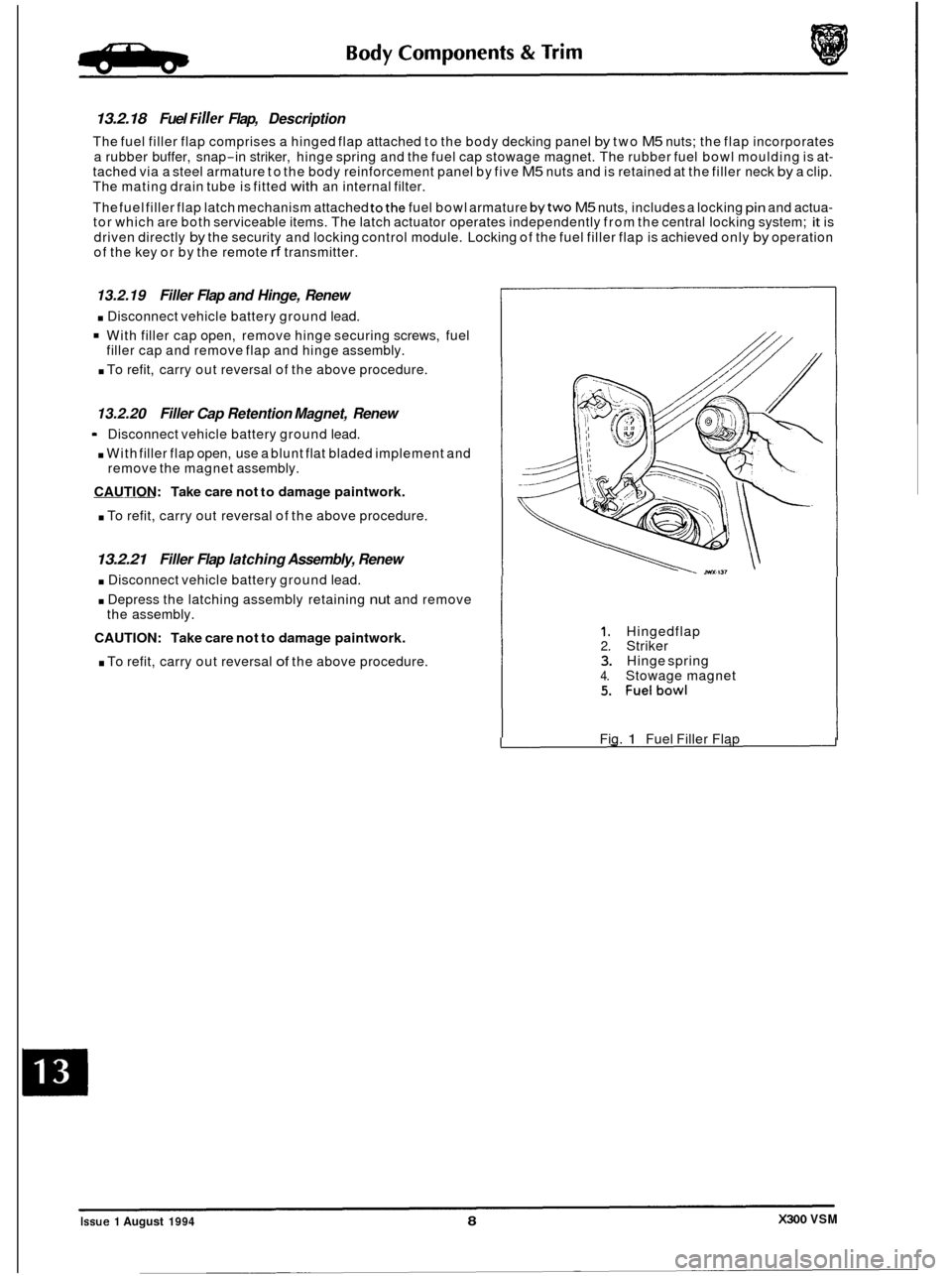
13.2.18 Fuel Filler Flap, Description
The fuel filler flap comprises a hinged flap attached to the body decking panel by two M5 nuts; the flap incorporates
a rubber buffer, snap
-in striker, hinge spring and the fuel cap stowage magnet. The rubber fuel bowl moulding is at- tached via a steel armature to the body reinforcement panel by five M5 nuts and is retained at the filler neck by a clip.
The mating drain tube is fitted with an internal filter.
The fuel filler flap latch mechanism attached
tothe fuel bowl armature bytwo M5 nuts, includes a locking pin and actua- tor which are both serviceable items. The latch actuator operates independently from the central locking system; it is
driven directly
by the security and locking control module. Locking of the fuel filler flap is achieved only by operation
of the key or by the remote rf transmitter.
13.2.19 Filler Flap and Hinge, Renew
. Disconnect vehicle battery ground lead.
With filler cap open, remove hinge securing screws, fuel
. To refit, carry out reversal of the above procedure.
filler cap
and remove flap and hinge assembly.
13.2.20 Filler Cap Retention Magnet, Renew
. With filler flap open, use a blunt flat bladed implement and
CAUTION: Take care not to damage paintwork.
. To refit, carry out reversal of the above procedure.
Disconnect
vehicle battery ground lead.
remove the magnet assembly.
13.2.21 Filler Flap latching Assembly, Renew
. Disconnect vehicle battery ground lead.
. Depress the latching assembly retaining nut and remove
CAUTION: Take care not to damage paintwork.
. To refit, carry out reversal of the above procedure.
the
assembly.
1. Hingedflap 2. Striker 3. Hinge spring 4. Stowage magnet 5. Fuelbowl
Fig. 1 Fuel Filler Flap
X300 VSM Issue 1 August 1994 8
e
0
0
Page 294 of 521

13.4.2
SRO 76.19.22
Raise trunk lid.
. Remove the trunk floor carpet (1 Fig. I), see subsection
13.4.4.
. Remove the trunk front liner (2 Fig. I), see subsection 13.4.5.
. Remove the trunk seal retainer (5 Fig. I), see subsection 13.4.6.
. Displace and remove the trunkside liner (3 Fig. I), passing
the fuel filler manual release cable through the liner.
9 Fit and align the new trunk side liner, passing the fuel filler
manual release cable through the liner.
. Refit the trunk seal retainer.
. Refit the trunk front liner.
. Refit the trunk floor carpet.
Trunk Side Liner - Left Hand, Renew
13.4.3 Trunk
Side liner
- Right Hand, Renew
SRO 76.19.23
Raise the trunk lid.
. Remove the trunk floor carpet (1 Fig. I), see subsection
. Remove the trunk front liner (2 Fig. I), see subsection
. Remove the trunk seal retainer (5 Fig. I), see subsection
. Displace and remove the literature pack from the trunk
. Displace and remove the trunk side liner (4 Fig. 1).
' Fit and align new side liner.
. Fit and align the literature pack to the trunk side liner.
. Refit the trunk seal retainer.
. Refit the trunk front liner.
. Refit the trunk floor carpet.
13.4.4.
13.4.5.
13.4.6.
side liner.
13.4.4 Trunk Floor Carpet, Renew
SRO 76.19.30
Displace and remove the trunk floor carpet assembly. 0
. Fit, align and seat new trunk floor carpet assembly.
13.4.5 Trunk Front Liner, Renew
SRO 76.19.31
Remove the battery cover.
. Remove the trunk floor carpet, see subsection 13.4.4.
. Displace and remove the trunk floor liner.
. Fit, align and seat new trunk front liner.
* Refit the trunk floor carpet.
. Refit the battery cover.
Fig. 1
Issue 1 August 1994 X300 VSM 39
Page 380 of 521

86.52.01
86.91 -83
19.75.21
86.80.24
Universal garage door opener
Security
& Locking Control Module
(SLCM)
Sunroof
Mirror memory control
Seat
/ Mirror Memory (Passenger.)
Speed control
Air conditioning
(NCCM)
Transmission control
Engine Management
BPU (Body Processor Unit)
ABS (Anti
-lock Braking System &
Traction Control (where fitted).
(ABS/TC CM)
Bulb failure
Rear
Front
I Power steering
I Column / mirror ECM
Reader exciter
Location
Roof console panel
LH side upper wheel arch, inside the
trunk below fuel filler pipe
Roof console panel.
Mounted inside driver's
& passenger's
seat.
Behind passenger knee bolster.
RH side of air conditioning unit.
Behind passenger knee bolster.
RH side footwell in front of 'A' post
behind cover.
Behind passenger knee bolster.
Engine compartment below
anti-lock
braking system modulator.
Trunk inside electrical carrier box,
Engine compartment behind each
headlamp assembly.
LH side footwell on
'A' post, behind cover.
On the side of steering column.
Around the lock barrel of steering
column.
Behind passenger knee bolster below the
airbag module.
Behind bumper, LHS of vehicle
Numb
11
13
10
9
14
2
RHD
20 LHD
1
16
RHD
(1 2&6)
7 LHD
(12&16)
6 (12&16)
19 RHD
3 LHD
18 RHD
4 RHD
12
22
& 24
17 5
8
15 RHD
23 LHD
21
X300 VSM 39 issue 1 August 1994
Page 384 of 521

SPECIFICATION - 1995 MODEL YEAR VEHICLES
Engine See relevant engine service manual
Engine Management System
VI2 ............................................................... Nippondenso
6cyl. .............................................................. LucasGEMS
Cooling System
Water pump
type
............................................................... Centrifugal
Cooling fans
- 6 cyl. ................................................ Two electric fans controlled by
Cooling fans
- VI2 ................................................. One engine driven fan and two
Cooling system control
............................................. Thermostat (two on V12)
Thermostat opening temperature .................................... 88OC
Fully open at ....................................................... 93,5 to 96OC
Filler cap pressure rating ........................................... 1,2 bar
drive
.............................................................. Belt
temperature sensor in radiator
electric fans controlled by
temperature sensor
in radiator
Fuel System Pump
one fitted on 6 cyl. (3.2 Liter and 4.0 Liter normally aspirated)
two fitted on 6
cyl. (4.0 Liter supercharged) and VI2
Electrical, module type, fitted in the tank. Integral 70 micron filter.
Make
.............................................................. Nippondenso
Fuel pressure (nominal)
............................................ 3,O bar
Second
pump switches at:
Pump
type
......................................................... Regenerative turbine
Fuel pressure (supercharged)
....................................... 3,7 bar max.
4.0 Liter supercharged ........................................... in at 4000 RPM
out at 3200 RPM
VI2 ............................................................ load sensitiveswitching
Clutch
Plate diameter .....................................................
Clutch hydraulic fluid ............................................... DOT 4
280mm single plate, LUK
Manual Transmission Ratios (Gefragl
First gear .......................................................... 3,553:l
Second gear ....................................................... 2,041: 1
Third gear ......................................................... 1,400 : 1
Fourth gear
........................................................ 1,000 : 1
Fifth gear
.......................................................... 0,755:l
Reverse ........................................................... 3,553: 1
Issue 1 August 1994 X300 VSM AI-95MY 1