1994 JAGUAR XJ6 wiring
[x] Cancel search: wiringPage 128 of 327

Electrical
0
FAULT CODE 24
Safing Impact Sensor Output Feed / Return Open Circuit
Normal Operation
The DM measures voltage level at pins 11 and 12 which varies in accordance with battery voltage. DM calculates what
the value at pins 11 and 12 should be from the value measured at pin 13, battery voltage. If voltage measured at pins 11 and 12 is not as expected by DM the MIL Lamp will illuminate and fault code 24 will be present, indicating a safing
sensor circuit fault.
Vbatt
9.0 9.5 1 10.0 10.5
11.0 i 11.5 12.0 12.5 I 13.0 13.5 14.0
14.5 15.0
15.5
Vpin 2.3 2.4 ~ 2.5
2.7
2.8 ~ 3.0
3.1 3.2 1 3.4 3.5 3.7 3.8 4.0
4.1
Possible Causes
0 Air bag wiring fault.
0 Safing impact sensor wiring fault.
0 Grounding of air bag /sensor circuits.
0 Intermittent battery voltage at DM pin 13.
16.0 4.3
Fault Diagnosis
1. Voltage - check
8 Disarm the SRS system.
8 Turn ignition switch OFF, then ON.
8 Measure the voltage between DM pins 11, 12 and pin 3 (ground) and compare to following table.
Are voltages within
0.5V of normal ?
Yes -
8 Check battery +ve input voltage wiring to DM pin 13.. Rectify wiring faults, if any.
8 Check fuse F17 in RH fuse-box, renew if blown.
8 Check battery, renew if necessary.
8 Renew DM if no other faults are located.
8 Proceed to step 2 if both voltages are low.
8 Proceed to step 3 if only one voltage is low.
N
O -
2. Resistance -check
8 Switch off the ignition
and disconnect battery earth lead.
8 Disconnect DM and measure resistance between pin 11 and pin 3.
8 Does resistance value indicate open circuit ?
Yes - Renew DM.
No
-Examine wiring andcomponents insafing sensor, air bag and primarysensorcircuitsforshortstoground. Rectify
faults as necessary.
3. Sensor - check
8 Switch on the ignition.
8 Disconnect safing sensor from main harness and measure resistance across connector wires YP and RN.
8 Is resistance less than 29 ?
Yes - Examine harness wiring for open circuit. Rectify faults as necessary.
No - Renew safing sensor.
4. On completion
8 Arm and verify the SRS system.
X300 EDM Issue 1 August 1994 15.1 - 22
Page 130 of 327

rl Electrical
FAULT CODE 32
Driver-side Air Bag Circuit High Resistance or Open
Normal Operation
The DM monitors the resistance between pins 10 and 11. The value of this resistance is the sum of the two cable reel
cassettes, the air bag and is normally between
1.5~2 and 2Q. If the resistance measured exceeds 4Q the MIL Lamp will illuminate and fault code 32 will be present, indicating high resistance or open circuit on the air bag circuit.
Possible Causes
0 Poor connections or corrosion at clockspring / main harness connections.
0 Open circuit or high resistance of cable reel cassettes.
0 Open circuit or high resistance in driver-side air bag.
0 Faulty driver-side air bag wiring.
Fault Diagnosis
1. Circuit - check
. Disarm SRS system and disconnect DM.
Disconnect DM and remove plastic locking wedge from black DM harness connector.
. Measure resistance across harness connections to passenger air bag, wires KN and RF!
. Is resistance value less than 2Q ?
Yes -
. Ensure locking wedge has been removed correctly from black connector.
. Examine harness for broken, dirty or incorrectly seated connections.
. Rectify faults as necessary.
No - Proceed to step 2.
2. Resistance -check
. Is resistance measured in step 1 greater than 352 7
Yes - Proceed to step 4.
No - Proceed to step 3.
3. Fault code verification
. Reconnect DM and check if code 32 is still present.
Yes
- Renew DM.
No - Examine harness or broken, dirty or incorrectly seated connections. Rectify faults as necessary.
4. Resistance -check
. Disconnect cable reel cassette at base of steering column.
Install air bag simulator (ensure 2Q resistance of simulator before connection) in place of cable reel cassette.
Measure resistance across harness connections to air bag, wires KIN and RI?
Is resistance equal to between 1.m and 2.2Q 7
Yes - Renew cable reel cassette.
No - Examine harness wiring for open circuit, rectify faults as necessary.
5. On completion.
. Arm and verify the SRS system.
0
0
0
0
Issue 1 August 1994 15.1 - 24 X300 EDM
Page 132 of 327

Electrical rl
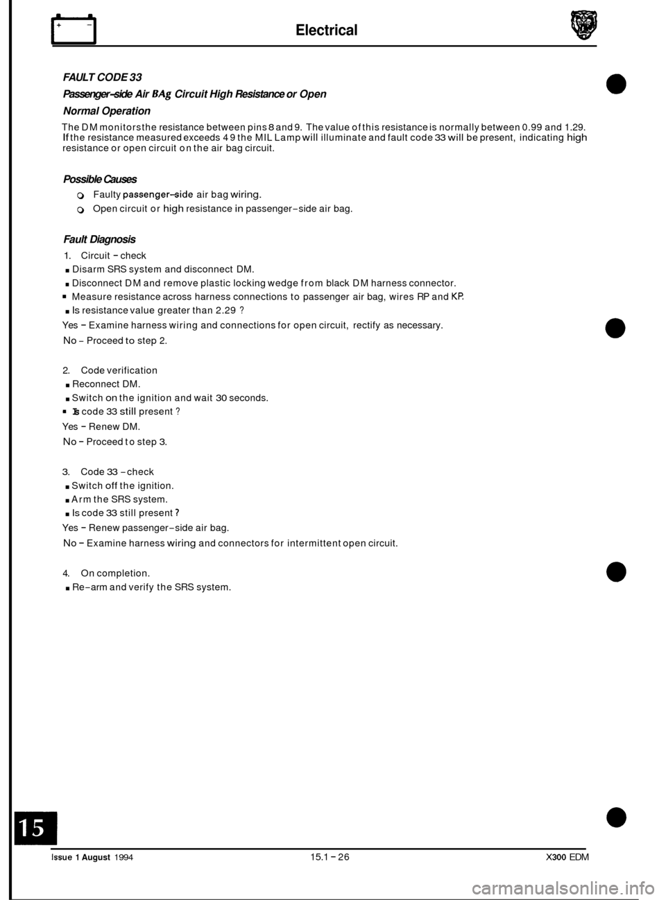
FAULT CODE 33
Passenger-side Air BAg Circuit High Resistance or Open
Normal Operation
The DM monitors the resistance between pins 8 and 9. The value of this resistance is normally between 0.99 and 1.29. If the resistance measured exceeds 49 the MIL Lamp will illuminate and fault code 33 will be present, indicating high resistance or open circuit on the air bag circuit.
Possible Causes
0 Faulty passenger-side air bag wiring.
0 Open circuit or high resistance in passenger-side air bag.
Fault Diagnosis
1. Circuit - check
. Disarm SRS system and disconnect DM.
. Disconnect DM and remove plastic locking wedge from black DM harness connector.
Measure resistance across harness connections to passenger air bag, wires RP and KP:
. Is resistance value greater than 2.29 ?
Yes - Examine harness wiring and connections for open circuit, rectify as necessary.
No - Proceed to step 2.
2. Code verification
. Reconnect DM.
. Switch on the ignition and wait 30 seconds.
Yes
- Renew DM.
No - Proceed to step 3.
Is code 33 still present ?
3. Code 33 -check
. Switch off the ignition.
. Arm the SRS system.
. Is code 33 still present 7
Yes - Renew passenger-side air bag.
No - Examine harness wiring and connectors for intermittent open circuit.
4. On completion.
. Re-arm and verify the SRS system.
rm
0
0
0
0
Issue 1 August 1994 15.1 - 26 X300 EDM
Page 134 of 327

rl E I ect r ica I
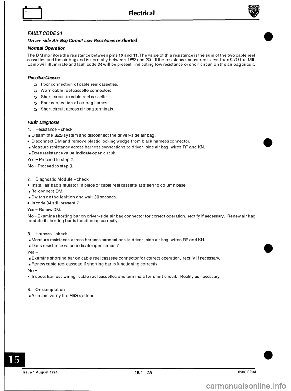
FAULT CODE 34
Driver-side Air Bag Circuit Low Resistance or Shorted
Normal Operation
The DM monitors the resistance between pins 10 and 11. The value of this resistance is the sum of the two cable reel
cassettes and the air bag and is normally between 1.552 and 2Q. If the resistance measured is less than 0.752 the MIL Lamp will illuminate and fault code 34 will be present, indicating low resistance or short circuit on the air bag circuit.
Possible Causes
0 Poor connection of cable reel cassettes.
0 Worn cable reel cassette connectors.
0 Short circuit in cable reel cassette.
0 Poor connection of air bag harness.
0 Short circuit across air bag terminals.
Fault Diagnosis
1. Resistance - check
. Disarm the SRS system and disconnect the driver-side air bag.
rn Disconnect DM and remove plastic locking wedge from black harness connector.
. Measure resistance across harness connections to driver-side air bag, wires RP and KN.
. Does resistance value indicate open circuit.
Yes
- Proceed to step 2.
No - Proceed to step 3.
2. Diagnostic Module -check
Install air bag simulator in place of cable reel cassette at steering column base.
. Re-connect DM.
. Switch on the ignition and wait 30 seconds.
rn Is code 34 still present ?
Yes - Renew DM.
No - Examine shorting bar on driver-side air bag connector for correct operation, rectify if necessary. Renew air bag
module if shorting bar is functioning correctly.
3. Harness -check
. Measure resistance across harness connections to driver-side air bag, wires RP and KN.
. Does resistance value indicate open circuit 7
Yes -
. Examine shorting bar on cable reel cassette connector for correct operation, rectify if necessary.
. Renew cable reel cassette if shorting bar is functioning correctly.
NO -
Inspect harness wiring, cable reel cassettes and terminals for short circuit. Rectify as necessary.
4. On completion
. Arm and verify the SRS system.
Page 136 of 327

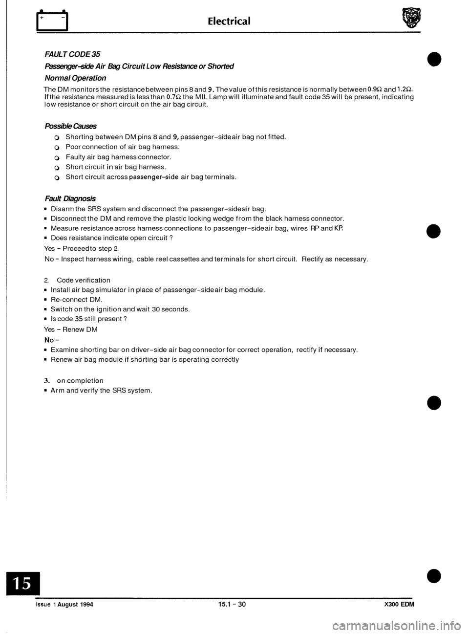
FAULT CODE 35
Passenger-side Air Bag Circuit L o w Resistance or Shorted
Normal Operation
The DM monitors the resistance between pins 8 and 9. The value of this resistance is normally between 0.9Q and 1.2Q. If the resistance measured is less than 0.7Q the MIL Lamp will illuminate and fault code 35 will be present, indicating
low resistance or short circuit on the air bag circuit.
Possible Causes
0 Shorting between DM pins 8 and 9, passenger-side air bag not fitted.
0 Poor connection of air bag harness.
0 Faulty air bag harness connector.
0 Short circuit in air bag harness.
0 Short circuit across passenger-side air bag terminals.
Fault Diagnosis
8 Disarm the SRS system and disconnect the passenger-side air bag.
8 Disconnect the DM and remove the plastic locking wedge from the black harness connector.
8 Measure resistance across harness connections to passenger-side air bag, wires RP and Kf?
8 Does resistance indicate open circuit ?
Yes - Proceed to step 2.
No - Inspect harness wiring, cable reel cassettes and terminals for short circuit. Rectify as necessary.
2. Code verification
8 Install air bag simulator in place of passenger-side air bag module.
8 Re-connect DM.
8 Switch on the ignition and wait 30 seconds.
8 Is code 35 still present ?
Yes - Renew DM
8 Examine shorting bar on driver-side air bag connector for correct operation, rectify if necessary.
8 Renew air bag module if shorting bar is operating correctly
NO -
3. on completion
8 Arm and verify the SRS system.
0
0
e
0
Issue 1 August 1994 15.1 - 30 X300 EDM
Page 138 of 327

rl E I ect r ica I
FAULT CODE 41
Front Right Impact Sensor Feed / Return Open Circuit
Normal Operation
The DM monitors and compares the voltages on pins 2 and 17. the voltage on both pins should be identical. If a discrep- ancy between the two measurements is detected the MIL Lamp will illuminate and fault code 41 will be present, indicat- ing open circuit between DM and RH impact sensor.
Possible Causes
0 Harness open circuit between DM pins 2 and 17 and sensor.
0 Internal open circuit in RH impact sensor wiring.
Fault Diagnosis
1. Circuit - check
. Disarm the SRS system.
. Disconnect DM.
. Measure resistance across harness connections to RH impact sensor, wires KU and ON.
. Is the resistance less than 251 ?
Yes - Renew RH impact sensor.
No - Proceed to step 2.
2.
Resistance -check
Disconnect RH impact sensor from main harness.
. Measure resistance across sensor terminals 1 and 2.
. Is resistance reading less than 251.
Yes - Examine harness wiring and connectors for open circuit.
No - Renew RH impact sensor.
4. On completion.
. Arm and verify the SRS system.
e
0
0
X300 EDM 15.1 - 32 Issue 1 August 1994
Page 140 of 327

E I ect r ical rl
FAULT CODE 42
Front L eft Impact Sensor Feed / Return Open Circuit
Normal Operation
The DM monitors and compares the voltages on pins 6 and 18. The voltage on both pins should be identical. If a dis- crepancy between the two measurements is detected the MIL Lamp will illuminate and fault code 42 will be present,
indicating open circuit between DM and LH impact sensor.
Possible Causes
0 Harness open circuit between DM pins 6 and 18 and the sensor.
0 Internal open circuit in LH impact sensor wiring.
Fault Diagnosis
1. Circuit - check
. Disarm the SRS system.
Disconnect DM.
. Measure resistance across harness connections to LH impact sensor, wires KG and YU.
. Is the resistance less than 28 ?
Yes - Renew LH impact sensor.
No - Proceed to step 2.
2. Resistance -check
. Disconnect LH impact sensor from main harness.
. Measure resistance across sensor terminals 1 and 2.
. Is resistance reading less than 28.
Yes
- Examine harness wiring and connectors for open circuit.
No - Renew LH impact sensor.
3. On completion.
. Arm and verify the SRS system.
Issue 1 August 1994 15.1 - 34 X300 EDM
Page 142 of 327

FAULT CODE 44
Front Right Impact Sensor Incorrectly Mounted to Vehicle
Normal Operation
The DM monitors the resistance value between pins 20 and 3. If a resistance of greater than 2.052 is detected the MIL
Lamp will illuminate and fault code 44 will be present, indicating incorrect mounting of the RH impact sensor. Secure
connections to ground at both the sensor case and the vehicle are necessary to avoid this fault.
Possible Causes
0 Poor or dirty connection between RH impact sensor case and vehicle ground.
0 Poor or dirty termination at impact sensor internal ground.
0 Open circuit on wiring between DM pin 20 and impact sensor ground terminal.
Fault Diagnosis
1. Circuit - check
Disarm the SRS system, and disconnect the battery earth lead.
. Disconnect the DM.
Measure resistance between DM pin 20 and pin 3 (ground).
. Is the resistance greater than 2.052.
Yes - Proceed to step 2.
No - Renew DM
2. Sensor - check
. Disconnect RH impact sensor from main harness.
. Measure resistance between sensor terminal 4 and ground.
. Is the resistance greater than 2.052 7
Yes -
. Remove sensor from mountings, clean all mounting surfaces (including chassis) and refit.
. Re-test resistance and renew sensor if value is still above 2.052.
NO -
. Examine harness for broken, dirty or incorrectly seated connectors.
3. On completion.
Arm and verify SRS system.
e
0