Page 1256 of 1413

Key-in Reminder System
lgnition Key Switch Test
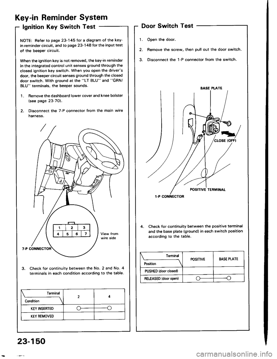
NOTE: Refer to page 23-145fot a diagram of the key-
in leminder circuit, and to page 23-148 Jor the input test
ol the beeper circuit.
When the ignition key is not removed, the key-in reminder
in the integrated control unit senses ground through the
closed ignition key switch. When you open the driver's
door, the beeper circuit senses ground through the closed
door switch, With ground at the "LT BLU" and "GRN/
BLU" terminals, the beeper sounds.
1 . Remove the dashboard lower cover and knee bolster
(see page 23-70).
2. Disconnect the 7-P connector from the main wire
harness.
Check for continuity between the No. 2 and No. 4
terminals in each condition acco.ding to the table.
l.
Door Switch Test
Open the door.
Remove the screw, then pull out the door switch.
Disconnect the 1-P connector from the switch.
4. Check lor continuity between the positive terminal
and the base plate (ground) in each switch position
according to the table.
BASE PLATE
Position
TerminalPOSITIVEBASE PLATE
PUSHED {door closedl
RELEASED ldoor o!en)oo
Terminal
Condition
4
KEY INSERTED--o
KEY REMOVED
23-150
Page 1264 of 1413
Lighting System
Combination Light/Turn Signal Switch Test
CAUTION:
a Atl SRS Oloctricsl wiring harnesses ar6 covered with
yellow insulation.
a Bslor€ disconnecting any pan ot the SRS wire har-
ness, connact the short connsctollsl.
a Replace the sntire aftectad SRS harne$ assembly if
it has an opon circuit or damagod wiring.
1. Remove the dashboard lower cover and steering
column covers (see page 23-71).
2. Disconnect the 4-P and 7-P connectors from the
switch.
3. Check the connector and socket tetminals to be sure
they are all making good contact. lf the terminals are
bent, loose, or cotroded, repair them as necessary,
and recheck the system.
4. Check tor continuitv between the terminals in each
switch position according to the table.
SRS MAIN HAR ESS
B
D
G
H
4-P CONI{ECTOR
7.P CONNECTOR
23-158
Page 1290 of 1413
Side Marker/TurnSignal/Hazard Flasher System
Component LocationIndex
23-184
GAUTION:
a All SRS electrical wiring harnessos ar6 covered with
yellow insulation.
a Belor€ disconnocting any pan of the SRS wire har-
ngss, connoct the short connector{s).
a Rsplace tho 6ntir€ affect€d SRS harnoss sssembly il
it has an op€n cilcuit or damaged widng.
TURN SIGNAL INDICATOR LIGHTS(ln the gauge assembly)
SRS MAIN HARI{ESS(Cov.rod with Ysllow in3ulationl
Bulb Locations,23-115
COMBINATION LIGHT SWITCHReplacement, page 23-160HAZARD WARI{ING SWITCHReplacement, page 23-187Test, page 23-187
Test, page 23-1
UNDER-DASHFUSE/RELAY 8OX
TURN SIGNAL/HAZARO RELAYInput Test, page 23-186
-
Page 1292 of 1413

Side Marker/Turn Signal/Hazard Flasher System
Turn Signal/Hazard Relay Input Test
CAUTION:
a All SRS electrical wiring harn6ss6s ar€ covered with
yellow insulation.
a B€foro disconn6cting any part of th€ SRS wire har-
noss, connoct tho short connector(s).
a Replaco tho ontiro sftoctod SRS harness ass€mbly it
it has an open circuit or damagod wiring,
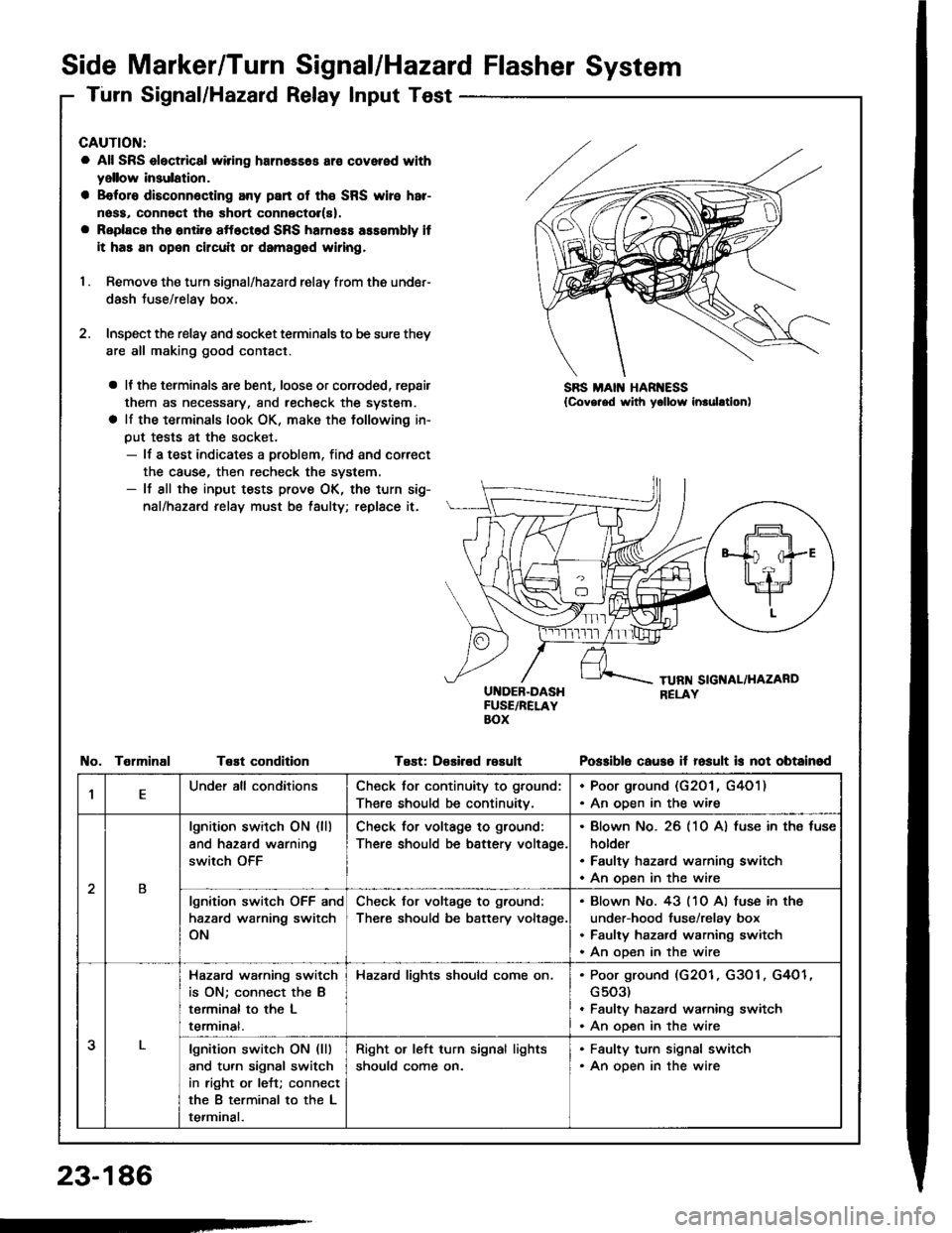
I . Remove the turn signal/hazard relay from ths under-
dash Juse/relay box.
2. Inspect the relay and socket terminals to be sure they
are all making good contact.
a It the terminals are bent, loose or coroded, repair
them as necessary, and recheck the system.
a lf the terminals look OK, make the tollowing in-
put tests at the socket.- lf a test indicates a problem, find and correct
the cause, then recheck the system.- lf all the input tests prove OK, the turn sig-
nal/hazard relay must be taulty; replace it.
UI{DEB-DASHFUSE/RELAYBOX
Test: D€sired rosult
SBS MAIN HAR ESS{Covg.ed with yollow inrulltion)
TelminalTeEt conditionPo$iblo causo it fosult is not obtainod
,lEUnder all conditionsCheck for continuity to ground:
There should be continuitv.
. Poor ground (G201 , G4O1). An oDen in the wire
2B
lgnition switch ON (ll)
and hazard warning
switch OFF
Check for voltage to ground:
There should be battery voltage.
Blown No. 26 (10 A) fuse in ths fuse
holder
Faulty hazard warning switch
An open in the wire
lgnition switch OFF and
hazard warning switch
ON
Check for voltage to ground:
There should be battery voltage.
Blown No. 43 (10 Al fuse in the
under-hood fuse/relay box
Faulty hazard warning switch
An ooen in the wire
3
Hazard wa.ning switch
is ON; connect the B
terminal to the L
termrnat.
Hazard lights should come on.Poor ground (G2O1, G3O1, G4O1
G503)
Faulty hazard warning switch
An open in the wire
lgnition switch ON (lll
and turn signal switch
in right or left; connect
the B terminal to the L
terminal.
Right or left turn signal lights
should come on.
. Faulty turn signal switch. An open in the wire
23-186
-
Page 1307 of 1413

Switch Test
CAUTION:
a All SRS el6ctrical wiring harnossos are covarod withyellow inaulation.
a Beforo disconnecting any pan ot the SRS wire har-neaa, connoct ths short connector(s).a Roplace the entil€ afloctod SRS harne$ a$6mbly ifit has an open circuit or dsmagad wlring.
NOTE; The original radio has a coded theft protection
circuit. Be sure to get the customer's code number before- disconnecting the battery.- removing the No. 32 {7.5 A) fuse lrom the under-hoodtuse/relav box.- removing the radio.
After service, reconnect power to the radio and turn iton. When the word "CODE" is displayed, enter the cus-tomer's 5-digit code to restore radio operation.
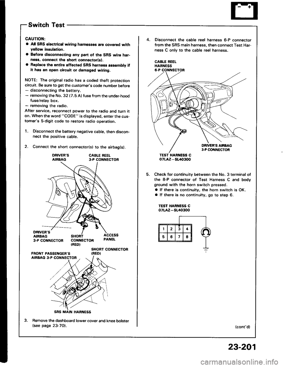
1. Disconnect the battery negative cable, then discon-nect the positive cable.
2. Connect the short connector(sl to the airbag(sl.
DRIVER'SAIRBAGCABLE REEL3.P CO NECTOR
DRIVER'SAIRBAG3-PCO'TNECTOR COI{NECTOR{RED}
ACCESSPAI{EL
SHORT CONTIECTOR{REO}
Remove the dashboatd lower cover and kne€(see page 23-701.
5.
4. Disconnect the cable reel harness 6-P connector
from the SRS main harness, then connect Test Har-
ness C onlv to the cable reel harness.
CABLE REELHARNESS
TEST HAR ESS CoTLAz - SL/l{,3OO
Check for continuity between the No, 3 terminal ot
the 8-P connector of Test Harness C and body
ground with the horn switch pressed.
a lf there is continuity, the horn switch is OK.a lf there is no continuity, go to step 6.
TEST HARNESS COTLAZ-SI/I()3OO
(cont'd)
bolster
23-201
Page 1317 of 1413
Moonroof
Gomponent Location lndex
a All SRS oloctrical wiring harnesses aro covared withyellow insulation,
a Eoforo disconnocting any part of tho SRS wire har-neaa, connoct th6 shon connector(sl.a Roplace th6 entire 8ff6cted SRS harness assombly ifit has an open circuit or damaged widng.
MOO BOOF SWTTCHRemov8l, page 23-214Test, page 23-215
SRS MAIN HARI{ESS{Covered with yellow insulation)
MOO ROOF MOTORTest, pag€ 23-215Replacoment, section 20
23-211
Page 1348 of 1413
Cruise Control
MAIN SWITCHTest, page 23-250Replacement, page 23-250
Component Location Index
a All SRS 6l6ctrical wiring harnessos aro covorod with
yallow insulation,
a Bofo.6 disconnecting any part of th6 SRS wire har-
ness, connoct th€ shon conneclor(s).
a Replaco the ontiro affected SRS halness assombly if
it has an op€n circuit or damagod widng.
SRS MAIN HARNESS(Cov.rod wilh yollow In.ulation)
CRUISE LIGHT(Built into gauge assembly)Bulb Locations, page 23-115
SET/RESUME SWITCHTest. page 23-248Repfacemont, page 23-248
BRAKE SWITCHTest. page 23-251
CLUTCH SWITCH (M/TI
Test, page 23-251
CRUISE CONTROLfnput Test, page 23-246A/T GEAR POSITIOI{swtTcHTest, page 23-136, 252
23-242
Page 1352 of 1413
Cruise Control
Control Unit Input Test
CAUTION:
a All SRS olectrical wi ng harnessos are covored with
yellow insulation.
a Botore disconnecting any part of th6 SRS wire har-
neaa, connect the short connoctor(sl.
a Roplace the €ntir€ affectod SRS hamass assembly il
il has an opan circuit or damaged wifng.
1 , Remove the dashboard lower cover and knee bolster(see page 23-70).
2. Disconnect the 14-P connector trom the control unit.
Insoect the connector and socket terminals to be
sure they are all making good contact.
a lf the terminals are bent, loose or corroded, repair
them as necessary, and recheck the system.
a It the terminals look OK, make the following in-
Dut tests at the connector.- It any test indicates a problem, find and cor-
rect the cause. then recheck the svstem.- lf allthe input tesls prove OK, the control unit
must be faulty; replace it.
CRUISE CONTROL UNIT
14-P COI{NECTOR
SRS MAIN HARNESS
23-246
Viow from wire side