Page 1407 of 1413
Supplemental Restraint System (SRSI
Gable Reel Replacement (cont'd)
Disconnect the connectors from the horn and cruise
control sevresume switches, then remove the cable
reel 3-P connector from its cliD.
8. Remove the steering wheel from the column.
9. Remove the upper and lower column covers.
UPPER COLUMN COVER
23-302
10.Disconnect the 6-P connector between the cable
reel and SRS main harness, then remove the con-
nector holder from the steering column.
'l l. Remove the cable reel from the column,
CABIT BEEL
CONNECTOF HOI-DER
Page 1409 of 1413

Supplemental Restraint System {SRSI
Cable Reel Replacement (cont'd)
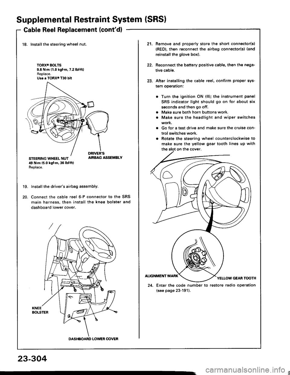
18. Installthe steering wheel nut.
TORXO BOLTS9.8 N.m (1.0 kgf.m,7.2lbtftlReplace.Us6 a TORX6 T30 bit
STEERING WHEEL NUT,19 N.m 15.0 kgt m, 36 lbt ft)Replace.
AIRBAG ASSEMBLY
19.
20.
Install the driver's airbag assembly.
Connect the cable reel 6-P connactor to the SRS
main harness, then install the knee bolster and
dashboard lower cover.
DASHBOARD LOWER OOVER
21.Remove and properly store the shon connector(s)
{RED}, then reconnect the airbag connector(s} (and
reinstall the glove box).
Reconnect the battery positive cable, then the nega-
tive cable.
After installing the cable reel, confirm proper sys-
l€m operalron:
Turn the ignition ON (ll); the instrument panel
SRS indicator light should go on for about six
ssconds and then go off.
Make sure both horn buttons work.
Make sure the headlight and wiper switches
work.
Go for a test drive and make sure the cruise con-
trol switches work.
Rotate the steering wheel counterclockwise to
make sure the yellow gear tooth lines up with
22.
23.
a
a
24. Enter the code number to restore radio operation
(see page 23-191).
23-304
Page 1410 of 1413
Dash Sensor Replacement
GAUTION:
. Oo not drmrgc the sensor wiring.. Do not instrll used SBS part3 from anothor c!t,When repairing an SRS: use only new part3.o Roplaco. 3onsor it it is dented, crackod, or doform.od.
NOTE; The original radio has a coded theft protectioncircuit. 8e sure to get the customer,s code numberbefore disconnecting the b€ttery cabres,
1. Oisconnect the battery negative cable and then theposative cable.
2. Remove the glove box damper (see section 201.then remove the glove box.
SHOBT CONNECTORIREDI
3. Connect the short connector(s) to the airbag(s).
DRIVER'SAIRBAG
DRNEN'SANAAG3.P CONNECTORSHORTCONNECTORIREDI
SRS MAIN HARNESS
Remove the footrest driver,s side only and door sillmolding, then pull the carpet back, and remove thedash sensor protector. (Left side shownj right sideis similar.)
DASHPROTECTOR
5. Remove the two mounting bolts. then remove thedash ssnsor.
(cont'd)
DASH SENSOB
MOUNTIITG BOLTS
23-305
Page 1412 of 1413

SRS Unit Replacement
CAUTION:
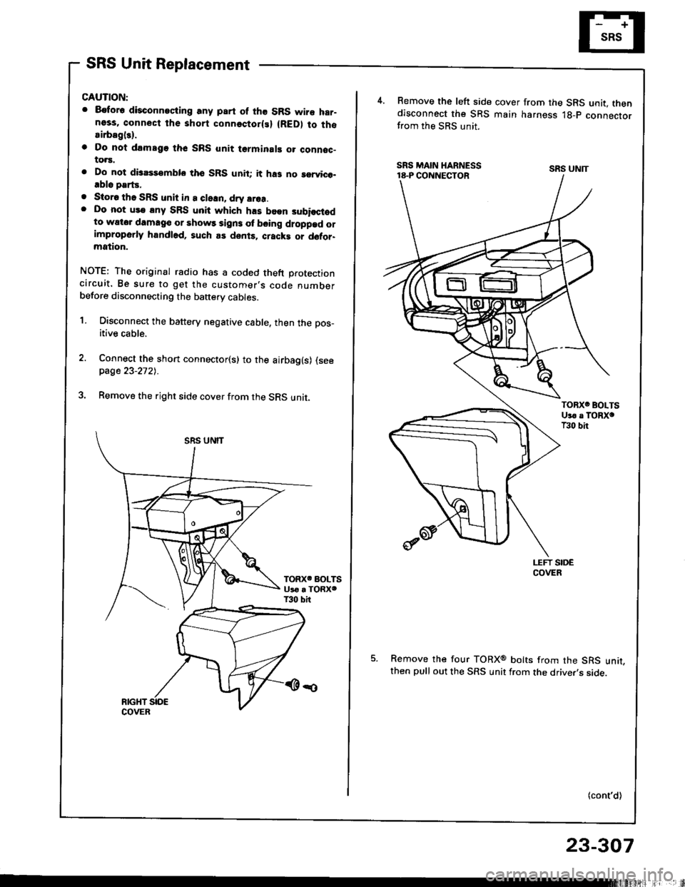
. 8€tor6 disconneciing any part of the SRS wire har-ness, connect the short connectorlsl (RED) to thosirbagl3).
o Do nol drmsgo thc SRS unit terminal! o. connoc-to.s.
. Do not disassemblo tho SRS unit; it ha3 no rervico-.blo parts.
. Storo tho SRS unit in a cleln, dry srea.. Do not us€ lny SRS unit which h.s been subisctodto wator damag€ or shows sign3 ol b€ing droppad orimproperly handl6d, such as dents. cracki or d6tor-mation.
NOTE: The original radio has a coded theft protectioncircuit. Be sure to get the customer,s code numberbefore disconnecting the baftery cables.
1. Disconnect the battery negative cable, then the pos_
itive cable.
Connect the short connector(s) to the airbag(s) (seepage 23-2721.
Remove the right side cover from the SRS unit.
4.Remove the left side cover from the SRS unit. thendisconnect the SRS main harness lg-p connectorfrom the SRS unit.
Remove the four TORXo bolts from the SRS unit,then pull out the SRS unit from the driver,s side.
(cont'd)
SRS UNIT
23-307
Page 1413 of 1413

Supplemental Restraint System {SRSI
SRS Unit Replacement (cont'd)
CAUTION: B€ suro to install tho SRS wiring ro thlt it i3
not pinched or interfeling with other car plrts.
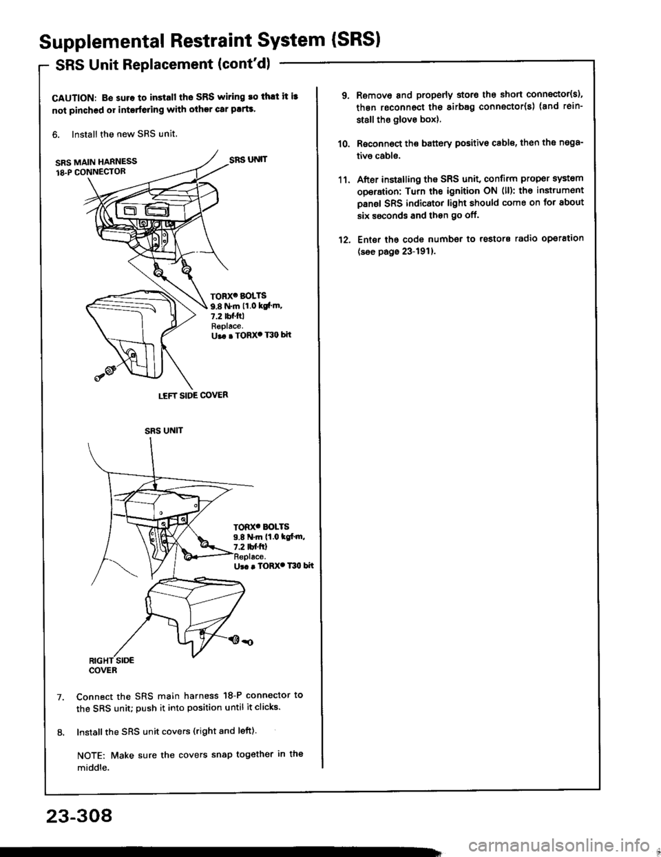
6. Install the new SRS unit,
SRS MAIN HARNESS
18.P CONN€CTOR
Ur. . TORX. T30 bit
Connect the SRS main harness 18-P connector to
the SRS unit; push it into position until it clicks.
Install the SRS unit covers (right and left).
NOTE: Make sure the covers snap tog€ther in the
middle.
LEFT SIDE COVER
SRS UNIT
TORX' BOLTS
9.8 N.m 11.0 ksl'm.7.2 tbf.ftlReplace.U.. . TORX' T30 bit
TOD(' BOLTS9.8 N.m (1.0 tc[.m,7.2 tbf.ftl
SRS UNIT
COVER
23-308
1'�l.
12.
Remove and properly storo the short connector{s),
thgn roconnect the sirb8g connector(s) (and rein-
st8ll tho glove box).
Roconnoct the battery positivo cable, th€n the n€98-
tivo cabls.
After installing the SRS unit, confirm proper system
operation: Turn the ignition ON (ll): th€ instrumont
panel SRS indicator light should come on for about
six ssconds and then go off.
Ent6r tho code number to rostors radio operation
(see page 23-191).