Page 154 of 1413
Cylinder Block
Inspection (cont'dl
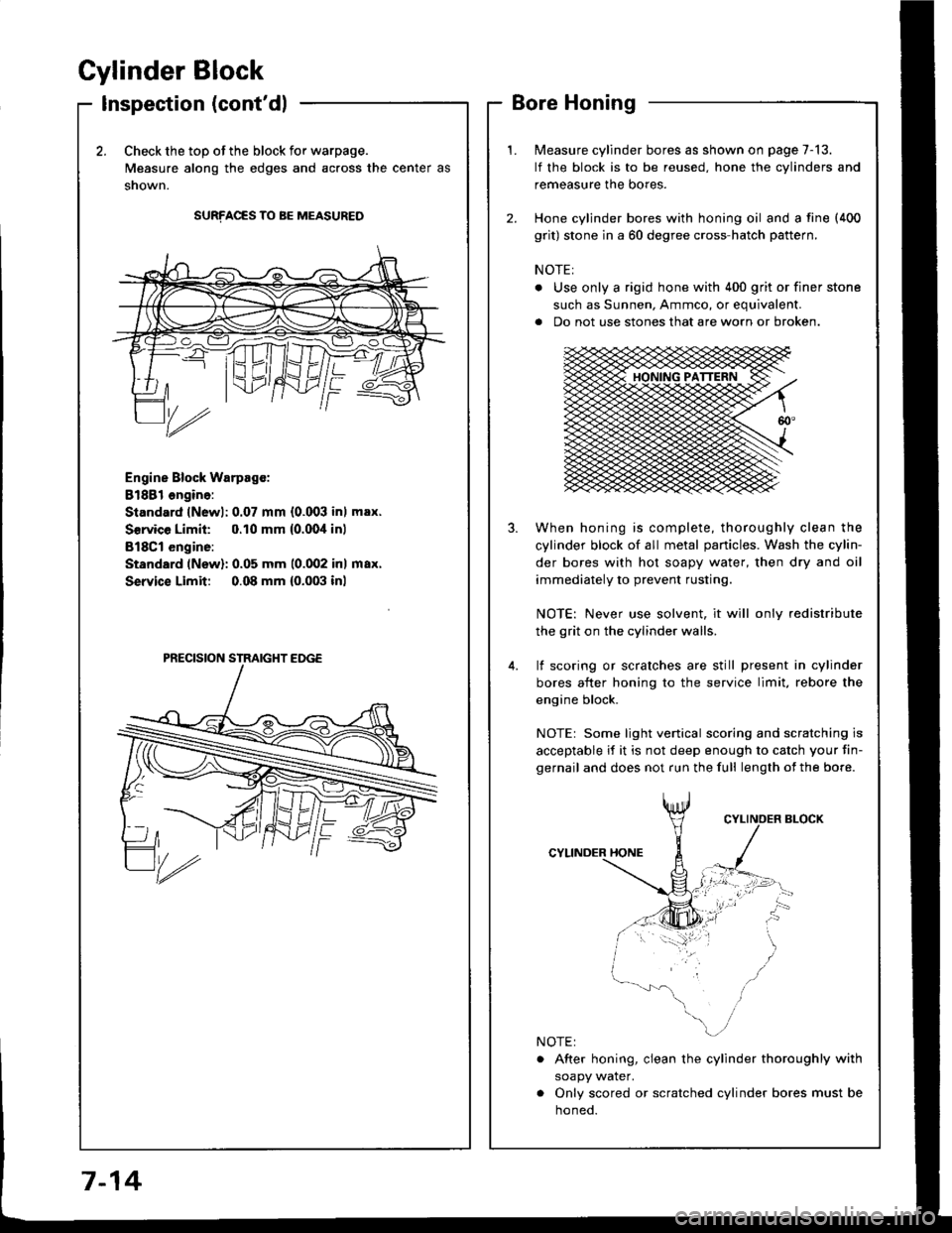
2.Check the top of the block for warpage.
Measure along the edges and across the center as
snown.
SURFACES TO BE MEASURED
Engine Block Warpsgc:
81881 ongine:
Standard lNewl: 0.07 mm {0.003 inl max.
Service Limil: 0.10 mm {0.00,1inl
B18Cl engine:
Standard (New): 0.05 mm 10.002 inl max.
Service Limit 0.08 mm {0.003 inl
Measure cylinder bores as shown on page 7-13.
lf the block is to be reused, hone the cylinders and
remeasure the bores.
Hone cylinder bores with honing oil and a fine (400
grit) stone in a 60 degree cross-hatch pattern.
NOTE:
. Use only a rigid hone with 400 grit or finer stone
such as Sunnen, Ammco, or equivalent.
a Do not use stones that are worn or broken.
When honing is complete, thoroughly clean the
cylinder block of all metal panicles. Wash the cylin-
der bores with hot soapy water, then dry and oil
immediately to prevent rusting.
NOTE: Never use solvent, it will only redistribute
the grit on the cylinder walls.
lf scoring or scralches are still present in cylinder
bores after honing to the service limit, rebore the
engine block.
NOTEr Some light venical scoring and scratching is
acceptable if it is not deep enough to catch your fin-
gernail and does not run the full length of the bore.
CYLINDER HONE
. After honing, clean the cylinder thoroughly with
soapy water.
. Only scored or scratched cylinder bores must be
noneo.
7-14
Page 155 of 1413
Pistons
Inspection
1. Check the oiston for distortion or cracks.3, Calculate the difference betw€on cvlinder bore
diameter on (see page 7-13) and piston diametsr.
Pbton-io"Cy'indor Clea18nco:
Stsndard (Nrwl: 0.010 - 0.0/O mm
{o.ofira - 0.0016 in}
S.rvic. Limit: 0.05 mm {0.002 in)
NOTE: lf the cylinder is bored, an oversized piston
must be used,
2. Moasur€ the piston diameter at a point l5 mm
(0.6 in) from the bottom of the skin.
Pbion Diamat6r:
Standard lNowl: 80.S - 80.99 mm(3.188 - 3.189 inl
Sorvica Limit 80.97 mm (3.188 in)
lf the clearance is near or €xc€eds the service limit,
inspect the piston and cylinder block for excessive
wear.
Ov.rsizc Pilton Diamcter:
O.25t 81,23 - 81.21|rnm {3.1980 - 3.198'l in)
rKI
7-1
Page 156 of 1413
Piston
lnstallation
'1.
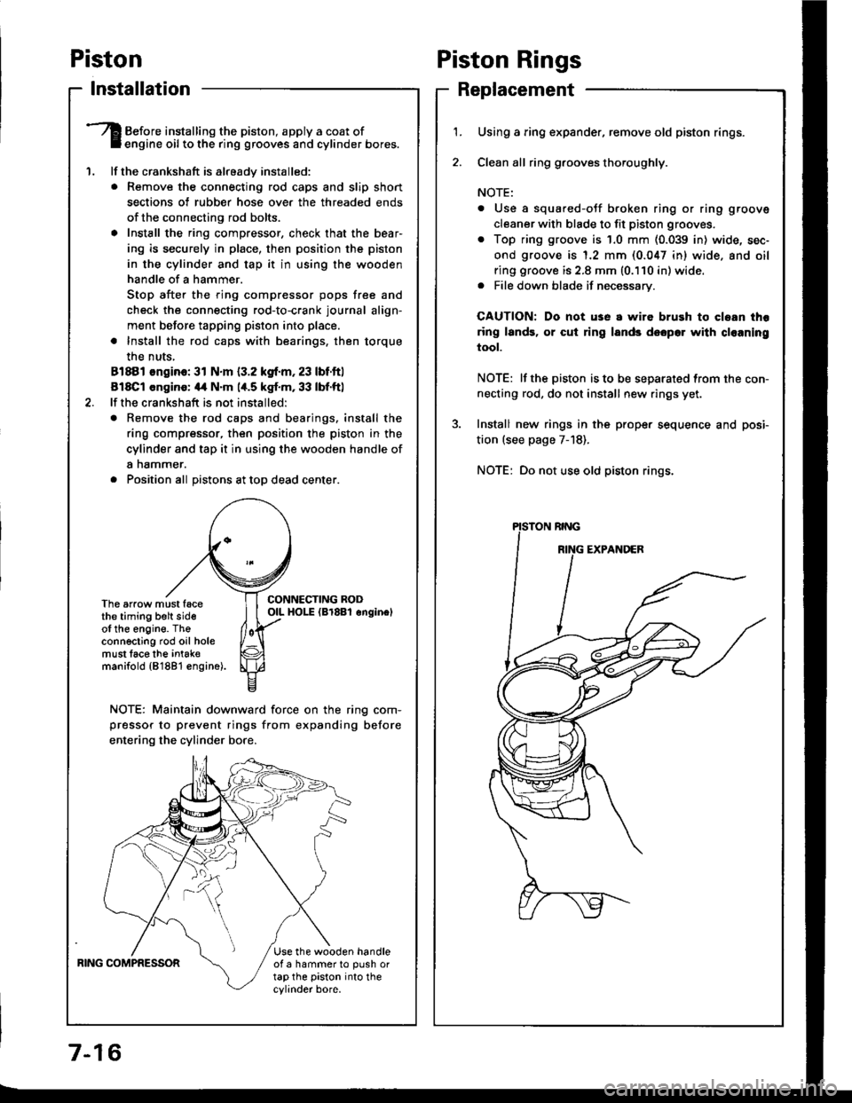
Before installing the piston, apply a coat ofengine oil to the ring grooves and cylinder bores.
lf the crankshaft is already installed:
. Remove the connecting rod caps and slip short
sections of rubber hose ove. the threaded ends
of the connecting rod bolts.
a Install the ring compressor, check that the bear'
ing is securely in place, then position the piston
in the cylinder and tap it in using the wooden
handle of a hammer.
Stop after the ring compressor pops free and
check the connecting rod-to-crank journal align-
ment before tapping piston into place.
. Install the rod caps with bearings, then torque
the nuts,
81881 ongino: 31 N.m {3.2 kgf.m, 23 lbf.ftl
818C1 cngino: 44 N'm 1,t.5 kgf.m, 33 lbf.ftl
lf the crankshaft is not installed:
o Remove the rod caps and bearings. install the
ring compressor, then position the piston in the
cylinder and tap it in using the wooden handle of
a nammer.
. Position all Distons at toD dead center.
CONNECTING RODOIL HOI-E (Br8Bl onginelThe arrow must facethe timing belt sideof the engine. Theconnecting rod oil holemust lace the intak€manifold {81881 €ngine).
NOTE: Maintain downward force on the ring com-
pressor to prevent rings from expanding before
entering the cylinder bore,
BING COMPRESSORUse the wooden handleof a hammer to push ortap the piston into thecylinder bore.
Piston Rings
Replacement
1.Using a ring expander, remove old piston rings.
Clean all ring g.ooves thoroughly.
NOTE:
. Use a squared-oJf broken ring or ring groove
cleaner with blade to fit piston grooves.
. Top ring groove is 1.0 mm (0.039 in) wide, sec-
ond groove is 1.2 mm (0.047 in) wide. and oil
ring groove is 2.8 mm (0.110 in) wide.. File down blade if necessary.
CAUTION: Do not use a wire brush to cloan thr
ring lands, or cut ring lands dsopo. with cl€aning
tool.
NOTE: lf the piston is to be separated from the con-
necting rod, do not install new rings yet.
Install new rings in the prope. sequence and posi-
tion (see page 7-18).
NOTE: Do not use old piston rings.
Page 157 of 1413
I
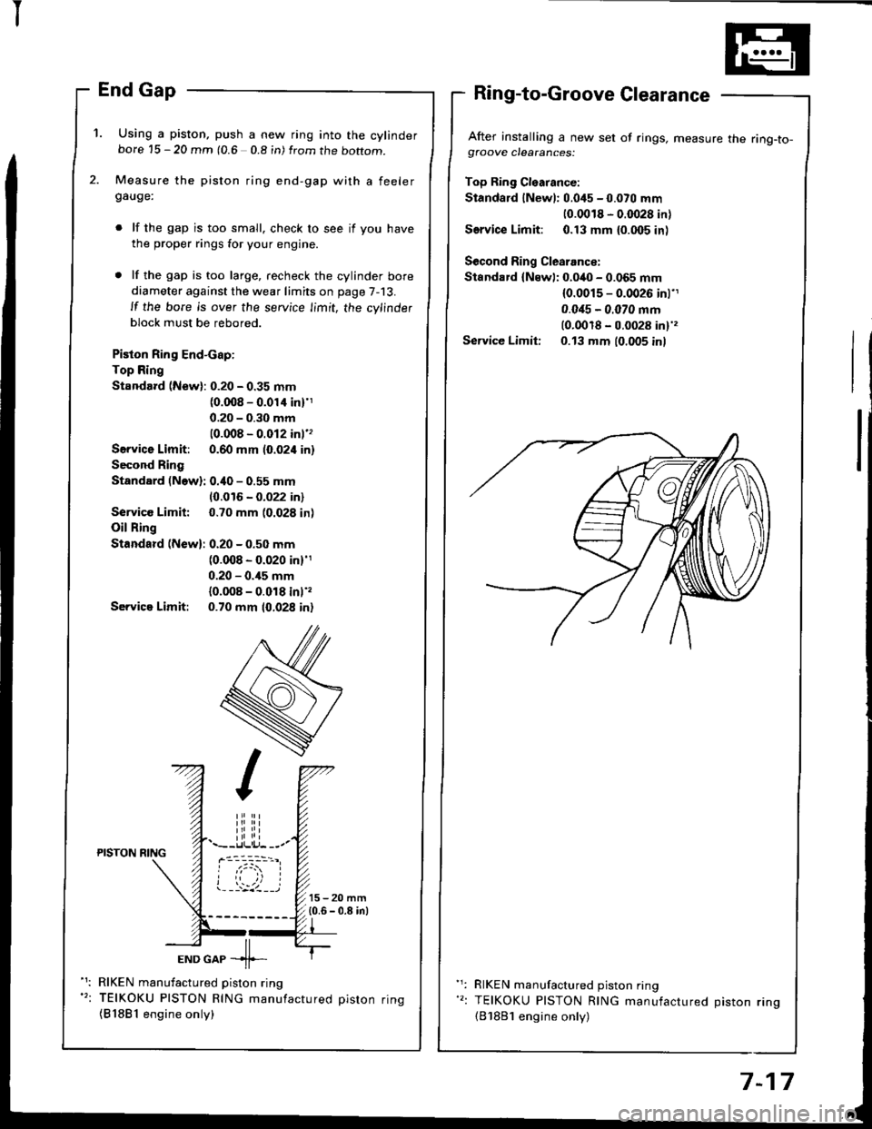
'1. Using a piston, push a new ring into the cylinderbore 15 - 20 mm (0.6 0.8 in) from the boftom.
Measure the piston ring end-gap with a feelergauge:
lf the gap is too small. check to see if you have
the proper rings for your engine.
lf the gap is too large, recheck the cylinder bore
diameter against the wear limits on page 7-13.
ll the bore is over the service limit, the cylinder
block must be rebored.
Piston Ring End-cap:
Top Ring
Standard (New): 0.20 - 0.35 mm(0.008 - 0.01'l inl'1
0.20 - 0.30 mm
10.008 - 0.012 inl''
Servica Limit: 0.60 mm (0.024 in)
Second Ring
Standard (Now): 0.40 - 0.55 mm
10.016 - 0.022 in)
Service Limit: 0.70 mm (0.028 in)
Oil Ring
Standard (New): 0.20 - 0.50 mm(0.008 - 0.020 in)'1
0.20 - 0.,15 mm
{0.008 - 0.018 inl',
Servica Limit: 0.70 mm 10.028 in)
After installing a new set of rings, measure the ring-to-gfoove clearances:
Top Ring Cl€arance:
Standard lNewl: 0.045 - 0.070 mm
10.0018 - 0.0028 in)
Service Limit: 0.13 mm {0.005 inl
Second Ring Clearance:
Standard {Newl: 0.040 - 0.065 mm(0.0015 - 0.0026 inl'1
0.0i15 - 0.070 mm(0.0018 - 0.0028 in)',
Service Limit: 0.13 mm (0.005 inl
iliiii.--r.llli.j- --.-PISTON NING
ioi
---'z llEND GAP -11--
RIKEN manufactured piston ring
TEIKOKU PISTON RING manufactured oiston rinq
{81881 engine only)
RIKEN manufactured piston ring
TEIKOKU PISTON RING manufactured Diston rino(B'1881 engine only)
7-17
Page 162 of 1413
Connecting Rods
Selection
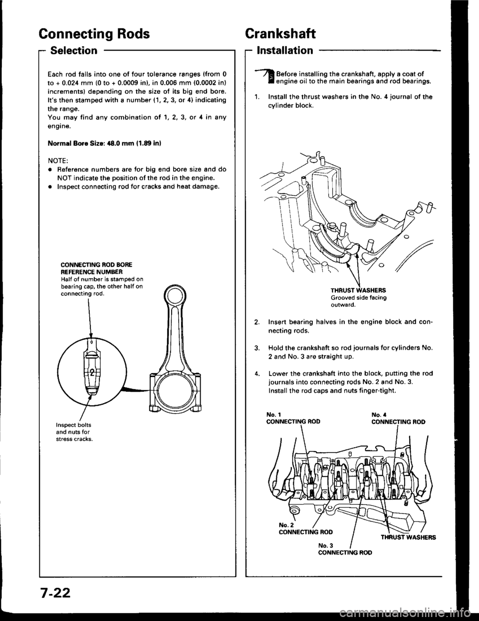
Each rod falls into one of four tolerance ranges (from 0
to + 0.024 mm (0 to + 0.0009 inl, in 0.006 mm {0.0002 in)
increments) depending on the size ot its big end bore.
It's then stamped with a number (1,2,3, or 4) indicating
the range.
You may find any combination ol 1, 2, 3, or 4 in any
engane.
Normsl Boro Sizoi ,18.0 mm 11.89 inl
NOTE:
a Reference numbers are Jor big end bore size and do
NOT indicate the position of the rod in the engine.
. Inspect connecting rod for cracks and heat damage.
CONNECNNG ROD BOREREFERENCE NUMBERHalf oI number is stamped onbearing cap. th€ other halfonconnecting rod.
Crankshaft
lnstallation
Before installing the crankshaft. apply a coat ofengine oil to the main bearings and rod bearings.
1. Install the thrust washers in the No. 4 iournsl of the
cvlinder block.
Grooved side tacingo!tward
Insert bearing halves in the engine block and con-
necting rods.
Hold the crankshaft so rod journals for cylinders No.
2 and No.3 are straight up.
Lower the crankshaft into the block. putting the rod
journals into connecting rods No.2 and No.3.
Install the rod caps and nuts finger-tight,
CONNECNNG ROD
7 -22
Page 164 of 1413
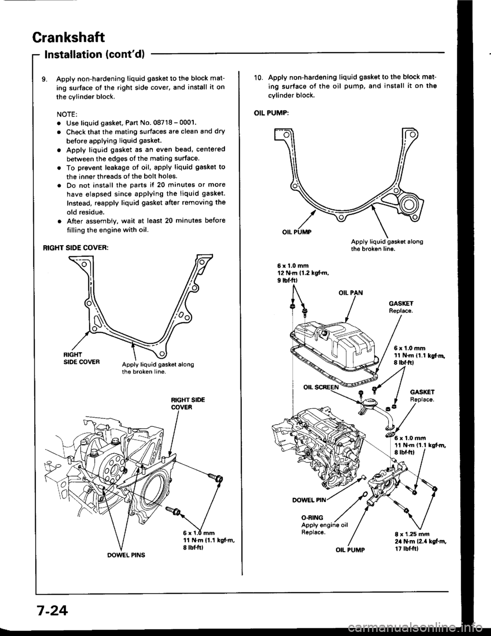
Grankshaft
Installation (cont'd)
9. Apply non-hardening liquid gasket to the block mat-
ing surface of the right side cover, and install it on
the cylinder block,
NOTE:
. Use liquid gasket, Part No. 08718 - 0001.
. Check that the mating surfaces are clean and dry
before applying liquid gasket.
. Apply liquid gasket as an even bead, centered
between the edges of the mating surface.
. To prevent leakage of oil, apply liquid gasket to
the inner threads of the bolt holes.
. Do not install the parts if 20 minutes or more
have elapsed since applying the liquid gasket.
Instead, reapply liquid gasket after removing the
old residue.
. After assembly, wait at least 20 minutes before
filling the engine with oil.
RIGHT SIDE COVER:
RIGHT SIDE
DOWEL PINS
7-24
R6plac€.
OIL PUMP
10. Apply non-hardening liquid gasket to the block mat-
ing surface of the oil pump, and install it on the
cvlinder block.
OIL PUMP:
DOWEL PIN
O.RING
6x1,0mmtl N.m {1.1 kgr'm.8 tbf.ftl
6x1.0mm
8 x 1.25 mm2il l$m l2.ia kg[.m.1t rbf.ftl
11 N.m {1.1 tgl.m,
Page 175 of 1413
Oil Pump
Overhaul
NOTE:
a Use new O-rings when reassembling.
a Apply oil to O-rings before installation.
. Use liquid gasket, Part No. 08718-OO01.
a After reassembly, check that the rotors move without binding.
6 x 1.0 mm6 N.m 10.6 kgl.m, 4 lbt'ttl
OUTER ROTORInspection, pages I 10, 11O.RINGReplace.
0
6 x 1.O mm11 N.m (1.1 kgf.m,8 tbf.frl
DOWEL PIN
PUMP COVERInspection, page 8-10
INNER ROTORInspect|on,page 8-1 1
8 x 1.25 mm24 N.m (2.4 kgf.m,t7 tbt'ft)
\SPRING
OIL SEALInstallation, Page 8-1 1Replace.
RELIEF VALVEValve must slide treelyin housing bore.Replace when scored.PUMP HOUSINGlnspection, pages 8-10, 11Apply liquid gasketto mating suface oIthe cylinder blockwhen installing.*\
8 x 1.25 mm24 N.m (2.4 kgl.m,17 lbl.Irl
SEALING BOLT39 N'm 14.0 kgf.m,29 tbt.ttt
Page 176 of 1413
Oil Pump
5.
4.
Removal/lnspection/lnstallation
6. Remov€ the timing belt.
7. R€move the drive pulley.
8. Remov€ the oil pan and oil screen.
9. Remove the oil pump.
Drain the engine oil.
Turn the crankshatt and align the white groove on
the crankshalt pulley with the pointer on the lower
cover.
Remove the cylinder head cover and middle cover.
Remove the power steering pump belt, air condition-
er belt and the alternator belt.
Remove the crankshaft pulley and remove the low-
er cover.
OIL PUMP
OIL PAN
8-10
1O. Remove the screws trom the pump housing, thsn
separate the housing and coveJ.
1 1. Check the inner-to outer roto. radial clearance on thepumP rotor.
Innor Rotol-to-Outor Rotor Radial Cloaranco
StandErd (Newl: O.O4-O.16 mm(0.O02-0.006 in)
Service Limit: O.2O mm (0.008 inl
Check the housing-to-rotor axial clearance
pump rotor.
Housing-to-Botor Axial Claalanc€
Standard (Nowl: O.O2-O.O7 mm(O.OO1 -O.OO3 inl
Service Limit: O.15 mm (0.006 in)
on the12.
HOUSING