Page 136 of 1413

lnstallation
Installthe cylinder head in the reverse order of removal:
NOTE:
. Always use a new head and manifold gasket.
. The cylinder head gasket is a metal gasket Take care
not to bend it.
. Rotate the crankshaft, set the No. 1 piston at TDC
(page 6-51).
. Do not use the middle cover and lower cover for
storing items disassembled.
. Clean the middle cover and lower cover before instal-
lation.
a Replace the washer when damaged or deteriorated
1. tnstall the cylinder head gasket. dowel pins and the
head oil control orifice on the cylinder head
NOTE: Clean the oil control orifice when installing.
O.RINGReplace.
HEADOIL CONTROLORIFICECloan.
2. Tighten cylinder head bolts in two steps. In the first
step, tighten all bolts in sequence to about 29 N'm
(3.0 kgf.m.22 lbf'ft). In the final step, tighten in
same sequence to 81 N.m (8.3 kgnm.60 lbf'ft).
NOTE: Apply clean engine oil to the bolt threads
and under the bolt head.
CYLINDER HEAD BOLT TOROUE SEOUENCE
11 x 1.5 mm81 N.m {8.3 kgf.m,60 lbf ft)
Install the intake manifold and tighten the nuts in a
crisscross pattern in two or three steps, beginning
with the inner nuts.
GASKETRePlace
8 x 1.25 mm23 N.m 12.3 kgl.m.17 tbf.ftt
8 x 1.25 mm24 N,m 12.,4 kgf m,17 tbf.ft)(cont'd)
6-75
Page 137 of 1413
Cylinder Head
8 r 1.25 mm2a N..n 12.4lgtm,r 7 tbf.ftl
Installation {cont'd)
4. Install the exhaust manifold and tighten the new
selJ-locking nuts in a crisscross pattern in two or
three steps, beginning with the inner nuts.
. Use new self-locking nuts.
SELF.LOCKING NUT8 x 1.25 mm31 N.m 13.2 kgf'm, 23 lbtltlReplace.
EXHAUST
a.l N.m 14.5 kgt m,33 tbr.trl
GASKETReplsco.
8 x 1.25 mm24 N.m (2.4 kgt m,rt tbfft)
&,x
6-76
5. Install the camshafts, camshaft oil seals and rubber
cap.
NOTE:
. Install the camshafts with keyway facing up.
o Installthe oil sealwith the spring side facing in.
. The oil seal housing surface should be dry,
. Set the O-ring and dowel pin in the oil passage
of th€ No. 3 camshaft holder
Kgyway is lacing up.
Apply liquid gasket around the rubber cap, then
install the rubber cap.
O-RING {ReDlace.)
Page 139 of 1413
11.
12.
13.
Cylinder Head
Installation lcont'd)
lnstallthe timing belt lsee page 6-51).
Adjust the valve clearance (see page 6-44).
Install the rubber seal in the groove of the cylinder
head cover. Seat the seal in the recesses for the
camshaft first, then work it into the groove around
the outside edges.
NOTE:
. Before installing the rubber seal. thoroughly
clean the seal and the groove.
. When installing, make sure the seal is seatedsecurely in the corners of the recesses with nogap.
COVER
6-78
14. Apply liquid gasket to the rubbe. seal at the eightcorne.s of the recesses.
NOTE:
. Use liquid gasket, Part No. 08718 - 0001.. Check that the mating surfaces are clean and dry
before applying liquid gasket.
a Do not install the parts if 20 minutes or more
have elapsed since applying liquid gasket.
Instead,.eapply liquid gasket after removing oldresidue.
r After assembly, wait at least 20 minutes beforefilling the engine with oil.
Apply liquid gasket tothe shaded areas.
Page 140 of 1413
When installing the cylinder head cover. hold the
rubber seal in the groove by placing your fingers on
the camshaft contacting surfaces (top of the semi-
circles).
Once the cylinder head cover is on the cylinder
head, slide the cover slightly back and forth to seat
the rubber seal.
NOTE:
Before installing the cylinder head cover, clean
the cylinder head contacting surfaces using a
shop towel.
Do not touch the pans where liquid gasket was
applied.
6x1.0mm9,8 N.m 11.0 kgt'm,7.2 tffirl
Tighten the nuts in 2 or 3 steps. In the final step'
tighten all nuts, in sequence, to 9.8 N'm (1.0 kgf'm,
7.2 tbf.ft).
After installing, check that all tubes, hoses and con-
nectors are installed correctly.
17.
6-79
Page 141 of 1413

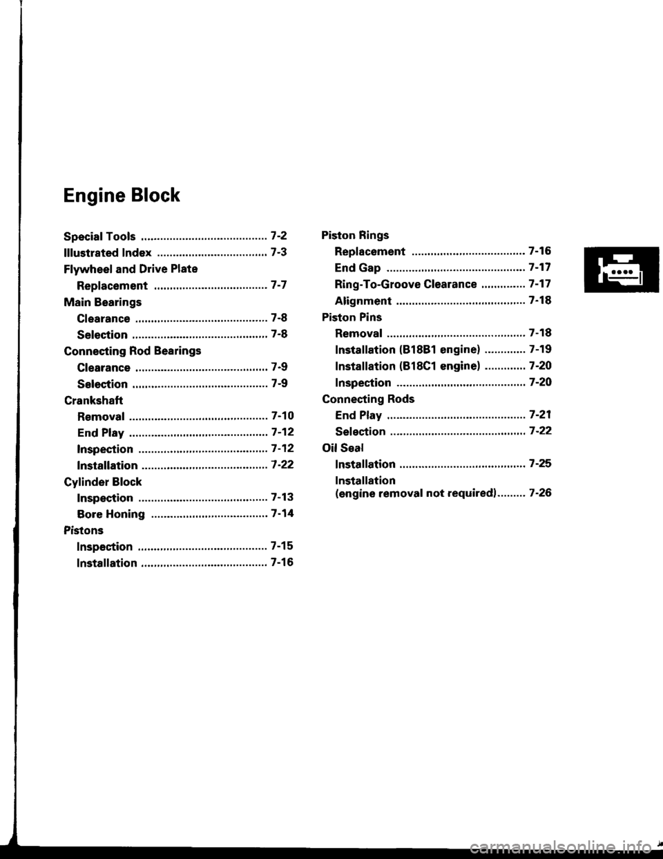
Engine Block
Speciaf Tools .............7'2
lllustrated Index ................................... 7-3
Flywheel and Drive Plate
Repfacement .........7-7
Main Bearings
Clearance ,.............. 7-8
Selection ................ 7-8
Connecting Rod Bearings
Clearance ............... 7-9
Selection ................ 7-9
Crankshaft
Removal .................7-10
End Play .................7-12
lnspection ........,,,.,,7-12
fnstallation .............7'22
Cylinder Block
Inspeetion ..............7-13
Bore Honing .....,.,,.7'14
Pistons
Inspaction ..............7-15
Installation .............7-16
Piston Rings
Replacement .........7-16
End Gap .................7-17
Ring-To-Groove C|earance,,,,.,,,...... 7 -17
Alignment ..............7-18
Piston Pins
Removal ........,........7-18
Installation (818B1 engine) ............. 7-19
fnstaffation (818C1 enginel ............. 7-20
fnspection ..............7-2O
Connecting Rods
End Play .................7-21
Sefeetion ..........,,,,,,7-22
Oil Seal
fnstaffation .............7-25
Installation
(engine removal not requiredl.. .......7-26
Page 146 of 1413

lllustrated IndexF
(cont'd)
NOTE: New rod bearings must be selected by
connecting rod and crankshaft identification
(see pages 7-8,9)
matching
marKrngs
Lubricate all internal parts with engine oil during
reassemorv.
PISTON RINGSReplacement, page 7'16Measurement. page 7-17Alignment, page 7 18
PISTON PINRemoval, page 7-18lnstallation, pages 7 19, 20Inspection, page 7'20
PISTON INSTALLATION DIRECTION
EXHAUST
INTAKE
Removal, page 7'11Measurement, page 7 15Inspect top of each cylinder borefor carbon build-up or ridgobetore removing piston.Remove ridge it necessary, page 7'11CONNECTING ROOEnd play, page 7-21
CONNECTING RODEEARINGSClearance, page 7-9Selection, page 7-9
CONNECTING ROD NUT818B1 ongine8x 0.75 mm31 N.m {3.2 kgf.m,23 lbf ftl818C1 engine9 x 0.75 mma,a N.m (4.5 kgt m, 33 lbf.ft|After torquing each bearangcap, rotate crankshaft tocheck for binding.
r-(,
Selection, page 7-22Small end measurement. page 7-21
BLOCXCylinder bore inspection, page 7 13Warpage inspection, page 7'14Cylinder bore honing, page 7-14
CONNECTING ROD BEARING CAPInstallation, page 7'23NOTE: Install caps so the bearing recess ison the same side as the recess in the rod.
r@
-1@
Page 151 of 1413

7.
8.
11.
9.
10.
Remove the rod caps/bearings. Keep all caps/bear-
ings in order.
Lift the crankshaft out of the engine, being careful
not to damage journals.
Remove the upper bearing halves from connecting
rods and set them aside with their resDective caDs.
Reinstall main caps and bearings on the engine in
oroDer order.
lf you can feel a ridge of metal or hard carbon
around the top of each cylinder, remove it with a
ndge reamer.
Follow the reamer manufacturer's instructions.
CAUTION: It the ridge is not removed, it may dam-
age the pistons as they are pushed oul.
CRANKSHAFT
RIDGE REAMER
12. Use the wooden handle of a hammer to drive the
prslons ouI.
CAUTION:
a Take care not to damage the contact surfaco ot
the metal gasket.
. When removing the piston/connecting rod, taks
caro not to hit the oil iot {818C1 sngins onlyl.
. It tho oil iet nozzlo is damag6d or bont, replaco
the oil ist assembly (818C1 engine only, page 8-
8).
Reinstall the rod bearings and caps after removing
each piston/connecting rod assembly.
Mark each piston/connecting rod assembly with its
cylinder number to avoid mixup on reassembly.
NOTE: The existing number on the connecting rod
does not indicate its position in the engine, it indi-
cates the rod bore size.
13.
14.
7-11
Page 153 of 1413

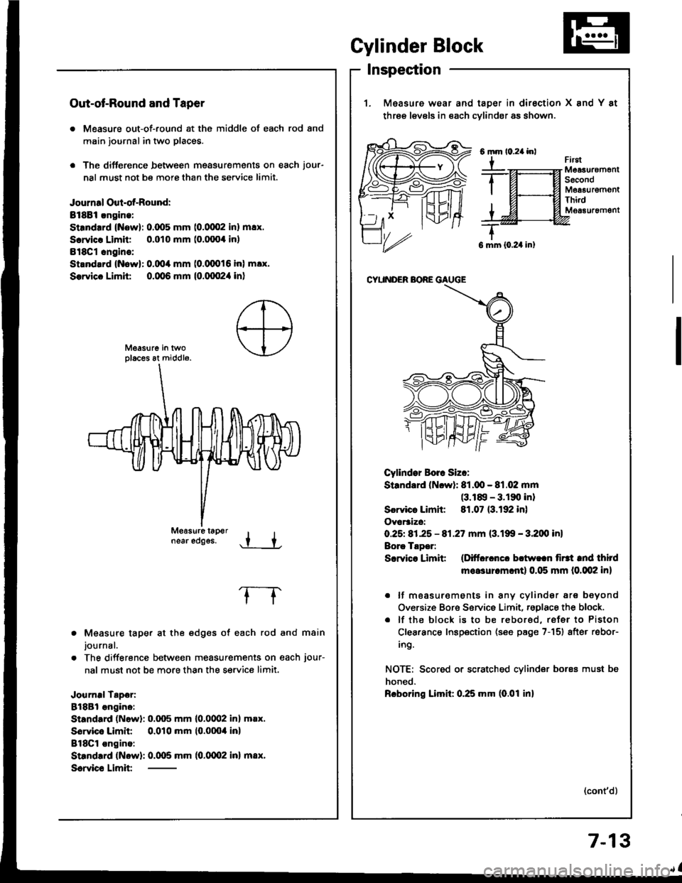
Out-ot-Round and Taper
. Measure out-of-round at the middle of each rod and
main journal in two places.
. The difference between msasurements on each jour-
nal must not be more than the se.vice limit.
Journal Oul-of-Round:
Bt8Bi.ngine:
Strndrrd (Now): 0.(x15 mm (0.0002 inl m!x.
Scrvicr Limit 0.010 mm (o.fixx inl
Bl8Cl cngins:
Strnd.rd {Nowl: 0.004 mm (0.(XD16 inl m!x.
Sorvicc Limit 0.qt6 mm {0.qx!2,1 in}
near edggs..t +
Measure taper at the edges of each rod and main
journal.
The difference between measurements on each jour-
nal must not be more than the service limit.
Journal Tapor:
8l8Bl angino:
Standard (Newl: 0.q)5 mm l0.0(Xl2 inl m.x.
Sorvico Limit 0.010 mm (0.0004 inl
BlSCl ongino:
Standrrd (Now): 0.005 mm (0.0002 inl m8x.
Scrvic€ Limit
frrgtMeaauremonlSecondMoa6urgmontThi.dM063uremgnt
G mm {0.24 in}
CYUNDER BORE GAUGE
Cyllndor Borr Siz.:
Standard (Ncwl: 81.q!- 81.02 mm(3.18, - 3.190 inl
Scrvicr Limh: 81.07 (3.192 in)
Ovar3izc:
O.25t 81.25 - 81.27 mm (3.199 - 3.200 inl
Borc Tlpor:
Scrvice Limit (Ditfcrcncc bctw!.n firtt tnd third
moasurcm.ntl 0.115 mm (0.002 in)
. lf moasur€ments in any cylindsr are beyond
Oversize Bore Service Limit, rsglace the block.
. lf the block is to be rebored, refer to Piston
Clearance Inspection (see page 7-151 after rebor-
ing.
NOTE: Scored or scratched cylinder bores must be
honed.
Rcboring Limil: 0.25 mm (0.01 inl
(cont'd)
Gylinder Block
Inspection
1. Measure wear and taDer in dirsction X and Y at
three levels in each cvlindsr as shown.
6mm
Y
7-13