Page 459 of 1413
Disconnoct the 22P connectortrom the TCM. Connecr tho T€stHarness "D" connector to thewhe harness onlv, not to the TCMlsee page '14-49).
Check for continuitv betweenbody ground and 017 terminaland D15 terminsl individually.
Rgpllr short in BLU/GRI{ otBLU|/EL wlro b€twgon Dl7 andDl5 torminsla and ths countar-rhaft apo€d sengor.
Reconnect the countershaftsDe00 sensor connector.
Msasure the rgsistance betweenD 1 7 and 015 terminals.
Rgpair looa6 ta.minsl or opon in8LU/GRN o. 8LU/YEL wiro bo-trvaon D'17 and D15 tormindgand tho count6rlhafl !p6gd!€ntor,
ls the r€sistance 4OO-600 07
Ch6ck for looaa TCM conn6cto..ll nocaslrry, aubrlitut6 a known-good TCM a.d .6ch.ck.
(cont'd)
4-67
Page 460 of 1413
Electrical Troubleshooting
Troubleshooting Flowchart (cont'dl
Possibl€ Caus6
. Disconnoct€d engine coolantt€mp€rature (ECTI sensor con-noctor. Short or open in the ECT sensor
. Faulty ECT s€nsor
Self-diagnosis E indicator lightblinks ten times.
Turn the ignition switch ON.
Check whether the MalfunctionIndicator Lamp {MlL} blinks (seesection 1 1)-
ls the MIL blinking?Rop.ir tho PGM-FI Syrt.m (!go
!.ction 111.
Turn the ignition switch OFF.
Disconnectthe 26P and 22P con-nectors trom the TCM.Connect the Test Harness "A"
and "D" conneclors to the wireharness only, not to the TCM (seepage 14 49).
Measure the voltage between theD'18 and A25 or A26 lorminals.
Bopair op.n or .hofi In WHT/BLKwiro botwoon tho O18 tanni.|al.nd the ECM.ls the voltage 4.75-5.25 V?
Turn the ignition switch OFF.
oooooooooooo
ooooooooooooooooooooooo
oooo o oo o
Dlal + I
Page 463 of 1413

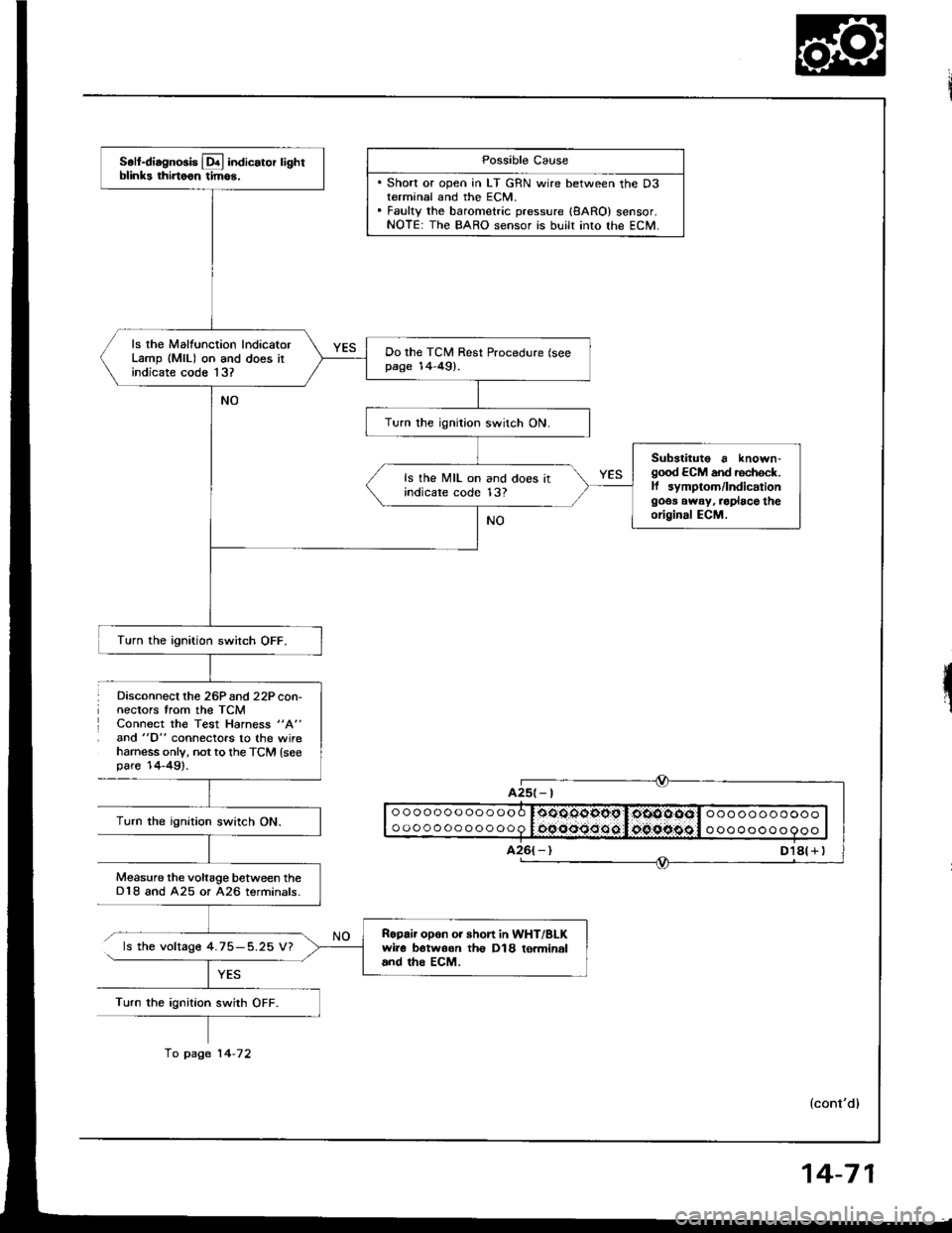
Disconnect lhe 26Pand 22P con-nectors trom the TCMConnect the Test Hahess "A"
and "D" connectors to the wireharness only, not to th€ TCM {seepare'14-49).
Possible Cause
. Short or open in LT GRN wire between the D3terminal and the ECM.. Fauky the barometric pressure {8ARO} sensor.NOTE: The BARO sensor is built into lhe ECM.
ooooooooooooo
oooooooooooo0oOOqgopg I,oiOOOOol ooo ooooooooooocqooo:Joo.oipggl o oooooo o 9ooTurn the ignition swirch ON.
Measure the voltage between theD18 and A25 or A26 terminals.
ls the voltage 4.75-5.25 V?
Turn the ignition swith OFF.
A25t- |
Soll-diagnosis Lq! indicator lightblinks thirtoon tim6.
ls rhe Malfunction lndicatorLamp (MlL) on and does itindicate code 13?
Do the TCM Rest Procedure (seepage 14-49).
Turn the ignition switch ON.
Substituto a known-good ECM and rechock.ll symptom/lndicationgoos away, .oplace theoriginal ECM.
ls the MIL on and does itindicare code 13?
Turn the ignition switch OFF.
Ropair opon or short in WHT/BLKwir6 botwoon th€ D18 to.minaland tho EcM.
fo page 14-72
14-71
Page 467 of 1413

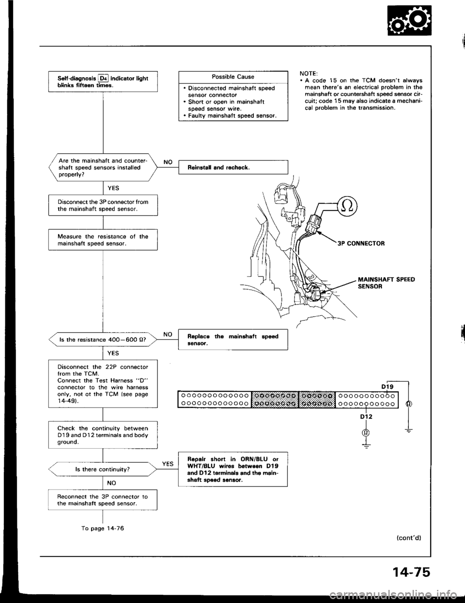
Possible Cause
. Disconnected mainshaft speedsensor connecror. Short or open in mainshaltspeed sensor wrre.. Faulty mainshatt speed sensor.
NOTE:. A code 15 on the TCM doesn't alwsysmean there's an electrical problem in themainshaft or countershaft speed sensor cir-cuit; code '15 may also indicate a mechani-cal Droblem in the transmission.
3P CONNECTOR
II o o o o o o o oo o o o o I:OtlO$O$g:Sl!:OlXOl*Ofill o o o o o o o o o O o | |
I ooooooooooooo l Sciii:ddii:ijii:l:i$idi$;d6#:l o oooop oo ooo | 6
"-f
1-L(0)Y-!
(cont'd)
solf-diagnosis E indicator lightblink tiftoon timos.
Are the mainshaft and counter-shalt speed sensors installedproperly?
Disconnect the 3P connector lromthe mainshaft speed sensor.
Measure the resistance ot themainshaft speed sensor.
ls the resistance 4OO-600 O?
Disconnect the 22P connectorfrom the TCM.Connect the Test Harness "D"
conneclor to the wire harnessonly, not ot the TCM (see page14-49).
Check the continuity betweenD19 and D12 terminals and bodyground.
Rcoair short in ORN/BLU otWHT/BLU wiros botween Dlgand Dl2 to.minals and tho main-shatt speod ronsor.
Reconnect the 3P connector tothe mainshatt speed sensor,
To page 14-76
14-75
Page 468 of 1413

Electrical Troubleshooting
Troubleshooting Flowchalt (cont'd)
From page 14-75ooooooooooooo
oooooooooooooooooooooooo
ooooooooooo
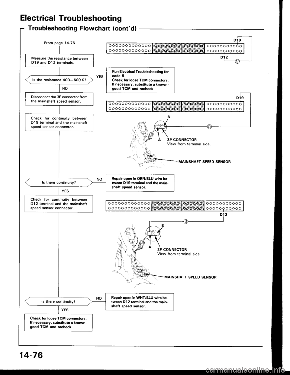
Measure the resistance betweenD19 and D12 terminals.
Run Electrical Troubleshooting folcode 9.Check for loos6 TCM connectors.It nocessary, substitute a known-good TCM and r.check.
ls the resistance 4O0-600 0?
Disconnecl the 3P connector fromthe mainshaft speed sensor.
Check tor continuitv betweenD19 terminal and the mainshaltspeed sensot connector.
Ropair op.n in ORN/BLU wir6 b6-tweon D19 terminal snd th€ main'shaft spa6d sensor.
Chock tgr continuity betweenD12 terminal and the mainshattspeed sensor connector.
Ropair open in WHT/BLU wire be-twe€n D12 tgrminal and th€ main-shaft sD6ed sonsor.
Chsck for loos€ TCM connoctors.ll noco$ary, substitute a known-good TCM and rocheck.
ooooooooooooo
ooooooooooooooooooooooo
ooooooooooo
ooooooooooooo
ooooooooooooo
ooooooooooo
ooooooooooo
MAINSHAFT SPEED SENSOR
3P CONNECTORView from terminal side
MAINSHAFT SPEED SENSOR
14-76
Page 477 of 1413
Mainshaft/Countershaft
Speed Sensors
Replacement
Disconnect the speed sensor connectors, then re-
move the harness clamp on the countershatt speed
sensor harness from the harness stay.
Remove the 6 mm bolts securing the mainshaft and
countershalt speed sensors from the transmission
housrng.
Remove the mainshaft and countershaft speed
sensors,
Installthe mainshatt and countershalt speed sensors
in the reverse order of the removal.
COUNTERSHAFTSPEED SENSOR
I{ARNESS STAY
6 x'l,O mml2 N.m{1.2 kgf.m,8.7 tbf.fr)
6 x 1.O mm12 N.m(1.2 kgf.m,8.7 tbf.ltl
14-85
Page 482 of 1413
Road Test
NOTE: Warm up the engine to operating temperature (the cooling fan comes on).
1 Apply parking brake and block th€ wheels. Start the engine, them move the selector lever to E] position whiledepressing the brake pedal. Depress the accelerator pedal, and release it suddenly. The engine should not stall,
2. Repeat same test in @ position.
3. Shift the selecto. lever to E position, and chock that the shift points occur at approximate speeds shown. Alsocheck fof abnormal noise and clutch slippage.
NOTE: Throttle position sensor voltage fepresents the throttle opening.
- 1 . Connect the Test Harness between the ECM and connector (see section 1 1).-2. Setthe digital multimeter to check voltage between D1 1{+)terminal and D22 { - ) terminal for the throttle Dosi-tion sensor.
TESTHARI{ESSOTLAJ_PT3OlOA
DIGITAL MULTIMETERCommarcially avsilablo o.KS-AHM-32-OO3
011 {+oooooooooooooooooooooooooooooooooooooooooooooooooooooooooooooooooooooooooooo
14-90
Page 483 of 1413

Throftle OpeningUnit of spe6dl st- 2nd2nd-3rd3rd-4th
Throttle position sensorvoltage: O.7 5 V
mph20-2227,30
Km/h17,O 19.O32.5 - 35.543.5-48.5
Throttle position sensorvoltage: 2.5 V
mpn
Km/h33.5 - 36.557.O-63.O89.O-95.O
Full-opened throttlemph30- 3462-6598- 101
Km/h49.O- 55.O99.O- 105.O1 57.O- 163.O
@ or @ Position
. Upshitt
Downshift
LOCK-Up
4. Accelerate to about 35 mph {57 km/h) so the transmission is in 4th, then shift from @ Oosition to E position.
The car should immediately begin slowing down from engine braking.
CAUTION: Do not shift from @ or @ position to @ of E position at speeds over 1OO mph (160 km/h); you
may damage the tlansmission,
5. Check lor abnormal noise and clutch slippage in the following positions.
E (1st Gear) Position- 1 . Accelerate from a stop at full throttle. Check that there is no abno.mal noise or clutch slippage.
-2. Upshifts should not occur with the selector in this position
E (2nd cear) Position.- 1 . Accelerate from a stop at full throttle. Check that there is no abnormal noise or clutch slippage.-2. Upshitts and downshitts should not occur with the selector in this position.
E {Reverse) Position
Accelerate from a stop at full throttle, and check for abnormal noise and clutch slippage.
6. Test in E {Parking) Position
Park car on slope (approx. 1 6o ), apply the parking brake, and shift into LE position. Release the brake; the car should
not move.
i
Throttle Op€ningUnit ot speed4th- 3rd3rd - 2nd2nd- l Et
Full-closed throttlemph1a-216-g (3rd- 1st)
Km/h29.O-33.O1O- 14 (3rd- lst)
Full-opened throttlemph85-8954- 5823-27
Km/h1 37.O- 143.08 7.0 - 93.037.0-43.O
Throttle OpeningUnit of speed
@ Position
Lock-uo control solenoidvalve A ON
Lock-up control solenoidvalve B ON
Throttle position sensorvoltage: 2,5 V
mpntJ- to17 -20
km/h21.O- 25.O2A.O-32.O
Full-opened throttlempn92-9692-96
km/h148.O - 1 54.0r 48.0,1 54.O
Throttlo OpeningUnit of sp6edE Position
Lock-up control solenoidvalve A ON
Lock-up control sol€noidvalv6 B ON
Throttle position sensorvoltage: 1.O Vmphb|-oJ61 63
kmih98- 10298- 102
Full-opened throttlemph85 8985-89
km/h137 143137 - 143
14-91