Page 1392 of 1413

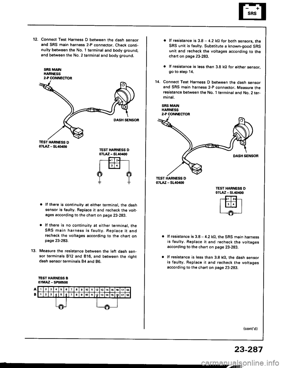
12.Connect Test Harness D between the dash sensorand SRS main harness 2-P connector. Check conti-nuity between the No. 1 terminsl and body ground,
8nd between the No.2 terminal and body ground,
sRs MA[{HARNESS2-P OOTTNECTOR
TEST HARNESS Do?LAiZ - SL()a(xt
. lf there is continuity at either terminal, the dashsensor is faulty. Replace it and recheck the volt-ages according to the chan on page 23-293.
. lf there is no continuity at either terminal, theSRS main harness is faulty. Replace it andrecheck the voltages according to the chart onpage 23-283.
Measure the resistance between the l6ft dash sen-sor terminals B'12 and Bl6, and between the rightdash sensor terminals B4 and 86.
IEST HARNESS B07MAZ - SPqt500
TEST HARNESS DotlA:z - sl(,(x)
rffi-l
??
t'l
o lt rssistance is 3.8 - 4.2 kO for both sensors. theSRS unit is faulty. Substitute a known-good SRSunit €nd recheck the voltages according to th€chart on page 23-283.
o lf resistancs is l6ss thsn 3.8 kO for either sensor.go to step 14.
1il. Connect Test Harness D between the dash sensorand SRS inain harness 2-P connector. Measure theresastance between the No. 1 terminal and No. 2 ter-minal.
SRS MAINHARNESS2.P CONNECTOR
TEST HAR ESS D07LAZ - SL.{)a(xl
TEST XARNESS DotlA:z - sl4|)4tx)
lf resistance is 3.8 - 4.2 kO, the SRS main harnessis faulty. Replace it and recheck the voltagesaccording to the chan on pag€ 23-283.
lf resistance is less than 3.8 kO, the dash sensoris faulty. Replace it and recheck the vottagesaccording to the chart on psge 23-283.
(cont'd)
23-287
Page 1393 of 1413
Supplemental Restraint System (SRS)
Troubleshooting (cont'd)
Modg C: Shon in one cowl son3ol, or open in both dash
sensors
Mode D: Open in ono da3h sensol
NOTE: The original radio has a coded theft protection
circuit. Be sure to get the customer's code number
before disconnecting the battery cables
1. Disconnect the battery negative cable and then the
positive cable. Then connect the short connector(s)
to the airbag(s) (see page 23'2721.
2. Connect Test Harness B between the SRS unit and
SRS main harness 18-P connector.
23-2AA
3. Measure the resistance between the left dash sen-
sor terminals 812 and 816, and between the right
dash sensor terminals 84 and 86.
lf resistance is more than 5 kO for eiiher set of
terminals, go to step 4.
lf resistance is less than 5 kO tor both sets of ter-
minals, the SRS unit is faulty. Substitute a
known-good SRS unit and recheck the voltages
according to the chart on page 23-283.
Page 1394 of 1413

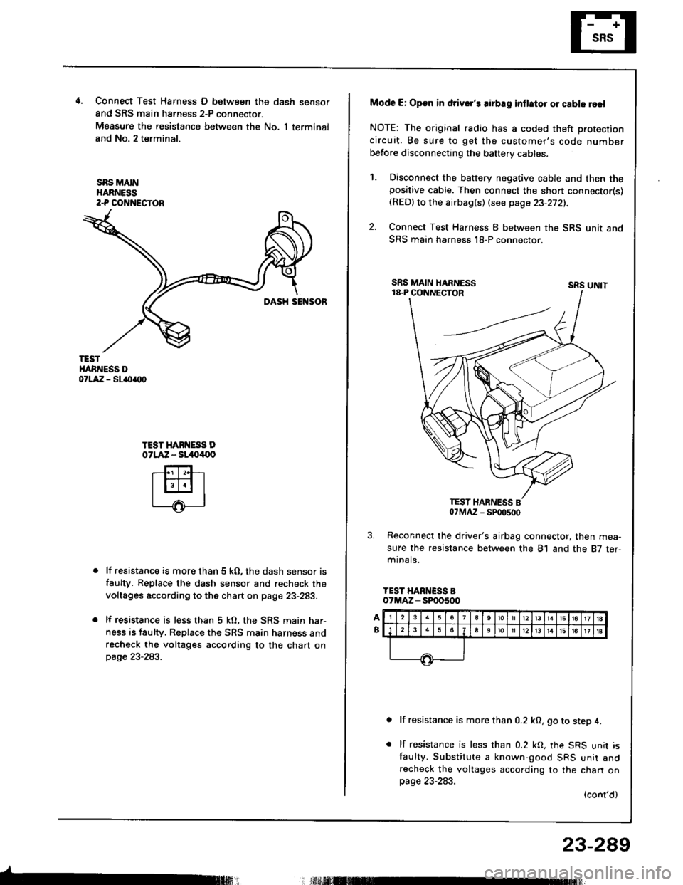
4.Connect T6st Harness D between the dash sensor
and SRS main harness 2-P connector.
Measure the resistance between the No. 1 terminal
and No. 2 terminal.
SBS MAINHARNESS2-P COI{NECTOR
TESTHARNESS DorlA:a - sl{tarx)
TEST HARI{ESS DOTLAZ - sl/to4{lo
lf resistance is more than 5 kO, the dash sensor is
faulty. Replace the dash sensor and recheck the
voltages according to the chart on page 23-283.
lf resistance is less than 5 kO, the SRS main har-
ness is faulty. Replace rhe SRS main harness and
recheck the voltages according to the chart onpage 23-283.
Mode E: Op€n in driver's airbag inflator or cable reel
NOTE: The original radio has a coded theft protection
circuit. Be sure to get the customer's code number
before disconnecting the baftery cables.
Disconnect the battery negative cable and then thepositive cable. Then connect the short connector(s)(RED)to the airbag(s) (see page 23-272).
Connect Test Harness I between the SRS unit and
SRS main harness l8-P connector.
sRs uNtt
Reconnect the driver's airbag connector, then mea-
sure the resistance between the 81 and the 87 ter,mr na ls.
TEST HARNESS Bo?MAZ - SP00500
lf resistance is more than 0.2 kO, go to step 4.
lf resistance is less than 0.2 kO, the SRS unit isfaulty. Substitute a known-good SRS unir andrecheck the voltages according to the chan onpage 23-283.
(cont'd)
23-289
; r.il M
1.
2.
Page 1410 of 1413
Dash Sensor Replacement
GAUTION:
. Oo not drmrgc the sensor wiring.. Do not instrll used SBS part3 from anothor c!t,When repairing an SRS: use only new part3.o Roplaco. 3onsor it it is dented, crackod, or doform.od.
NOTE; The original radio has a coded theft protectioncircuit. 8e sure to get the customer,s code numberbefore disconnecting the b€ttery cabres,
1. Oisconnect the battery negative cable and then theposative cable.
2. Remove the glove box damper (see section 201.then remove the glove box.
SHOBT CONNECTORIREDI
3. Connect the short connector(s) to the airbag(s).
DRIVER'SAIRBAG
DRNEN'SANAAG3.P CONNECTORSHORTCONNECTORIREDI
SRS MAIN HARNESS
Remove the footrest driver,s side only and door sillmolding, then pull the carpet back, and remove thedash sensor protector. (Left side shownj right sideis similar.)
DASHPROTECTOR
5. Remove the two mounting bolts. then remove thedash ssnsor.
(cont'd)
DASH SENSOB
MOUNTIITG BOLTS
23-305
Page 1411 of 1413

Supplemental Restraint System (SRSI
Dash Sensor Replacement (cont'dl
CAUTION:
. Be 3ure to install the harness wires so that theY ars
not pinchcd or interfering with othor car parte.
o Carefully inspest the dash sensors lor signs of boing
dropped or improperly handled,3uch as dents,
cracks or dsformation.
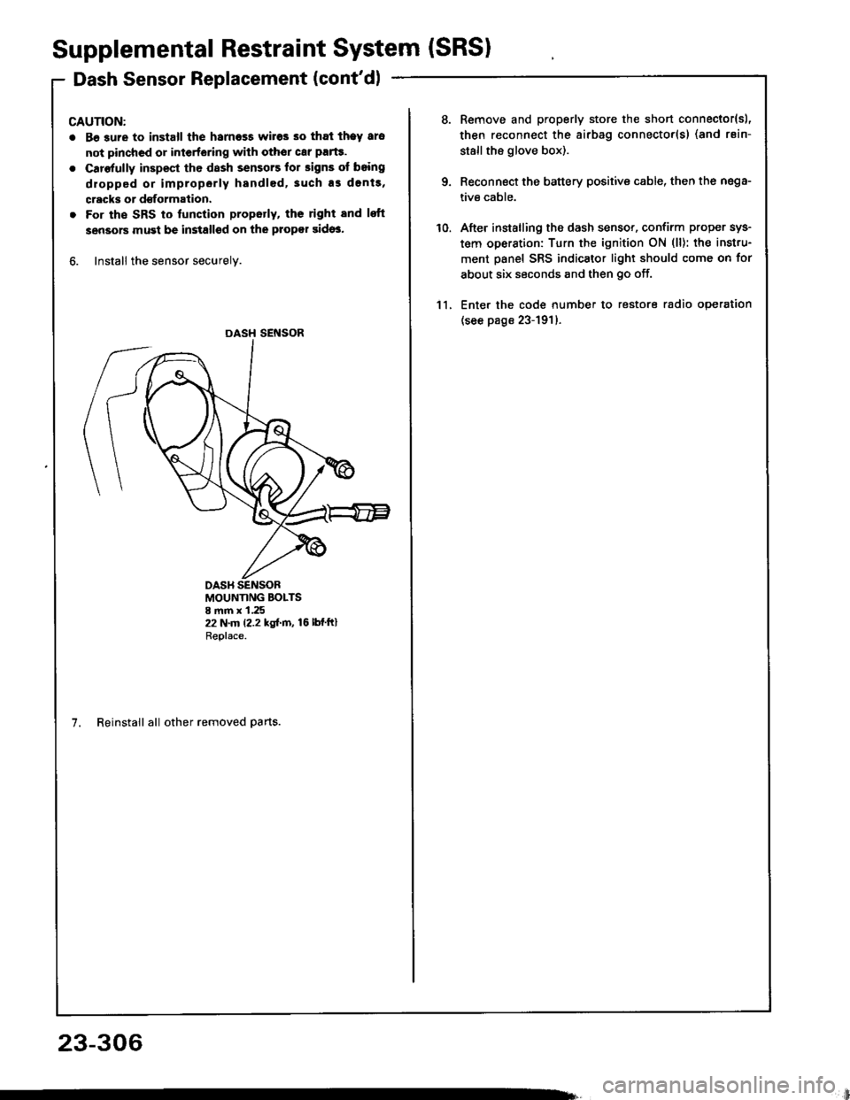
. For the SRS to lunction propotly, ths right and lsft
sensors must be installsd on the propor sidos.
6. Install the sensor securely.
DASH SENSOR
MOUNTING BOLTS8 mm x 1.2522 N.m (2.2 kgf.m, 16lbfftlReplace.
7. Reinstall all other removed parts.
23-306
li
10.
Remove and properly store the short connector{sl,
then reconnect the airbag connector(s) (and rsin-
stallthe glove box).
Reconnect the battery positive cable, then the nega-
tive cable.
After installing the dash sensor, confirm proper sys-
tem operation: Turn the ignition ON (ll): the instru-
ment panel SRS indicator light should come on for
about six seconds and then go off.
Enter the code number to restore radio operation
(see page 23-191)-
11.