Page 1375 of 1413
Supplemental Restraint System (SRSI
Wiring Locations
CAUnON: Make sure all SRS ground locrtion3 lrc clrln rnd ground3 tra |.curalv rltachad.
NOTE:
o Alt SRS electricsl wiring harnesses are covered with ysllow insulation.
. RsDlace the entire affected SRS harness assembly if it has an open circuit or damaged wiring.
CABIE REEL to DdrrEFS AnaAC3+ OOI{iECTOR
DASHBOARD WIRE HARNEi9to INDICATOB UGHT in GAUGE ASSEMBLY
5-P CONNECTOBaFs irA[t H^RiEssto FROiIT PASSEMIEFS Ana G3t coftf'Eclon
SRS MAIN HARNESS tO
MAIN WIRE HARNESS+P OONNECTOR
C. b Ra nod.ll
SnS Alt{ ll^ntc8s too sH SErson2+ OOt{tlEcT()R
SRS MAIN HARNESSto UNDER-DASHFUSE/RELAY BOX2"P @NNECTOR
MAIN WIRE HARNESSto DASHBOARD WIREHARNESSlGP CONNECTOR
SBS MAIN HARNESS toLEFT DASH SENSOR2.P CONNECTOA
23-270
Page 1383 of 1413

Supplemental Restraint System (SRS)
Troubleshooting
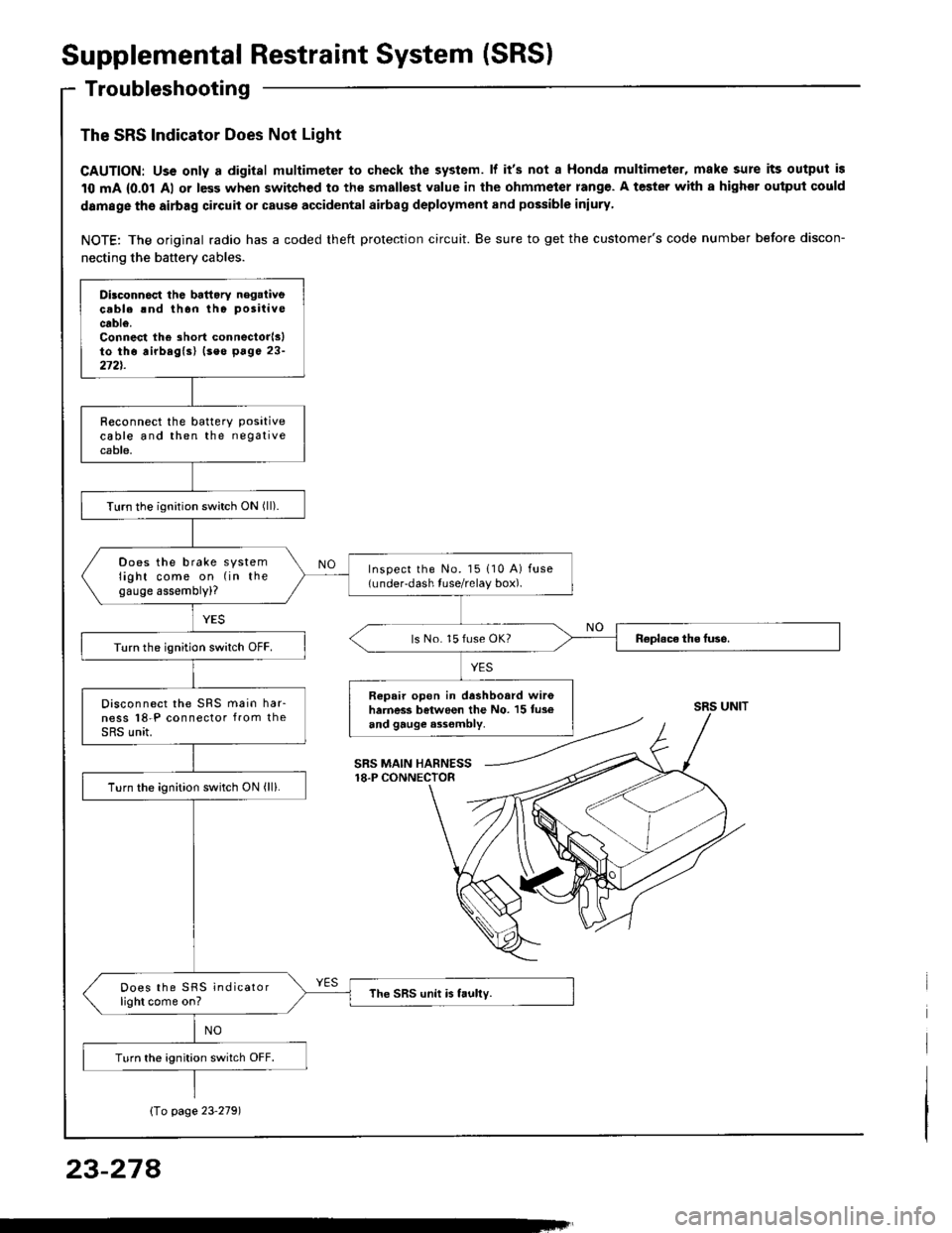
The SRS Indicator Does Not Light
CAUTION: Uss only a digital multimeter to check the system. lf it's not a Honda multimeter, make sure its output is
10 mA {0.01 Al or less when switched to the smallest value in the ohmmeter rang€. A tester with a highor ouiput could
damage the airbag circuit or cause accidental airbag deployment and possible iniury
NOTE: The original radio has a coded theft protection circuit. Be sure to get the customer's code number before discon-
necting the battery cables.
Dilconn6ct the battory negaiivecable rnd thon tho positive
cable.Connest the short connectorlslto tho airbaglsl (seo p6ge 23-272t.
R€connect the batterY Positivecable and then the negativecable.
Turn the ignition switch ON (ll).
Does the brake systemlight come on (in thegauge assembly)?
Inspect the No. l5 110 A) fuse(under-dash tuse/relay box).
ls No. 15 fuse OK?Turn the ignition switch OFF.
Repair open in dashboard wir6harness between the No. 15 tus€and gauge a3sombly.
Disconnect the SRS main har-ness l8-P connector from theSRS unit.
Turn the ignition switch ON (ll).
Does the SRS indicatorlight come on?The SRS unit is faully.
Turn the ignition switch OFF.
SRS UNIT
SRS MAIN HARNESS18.P CONNECTOR
Io page 23'2791
23-274
Page 1384 of 1413
SRS MAIN HABNESS(From plgr 23.27E1
DASHBOARD WIFE HARNESS5-P CONNECTOR
8tU{ +
@
I:
Disconnoct tho SRS m.in h6,-ng88 {-P conn6clor f,om thomrin wiao harn6$.
Tum lhq ignition switch ON (lll.
Doo3 tho SRS indic.torlight com6 on?Th. SRS rnlin h..n... i.t ulty.
Tu.n tho ignition switch OFF.
Romovo tho g!u0c !ss.mblyth6n inrpoct ths SBS indicatorlight bulb.
Raplaca lh. indlc.toi llOht birlb.
Connoct ! voltmotoa bdwoln thrNo. 5 lormin.l (+) of tho 5-P con-noctor rnd body ground (-).
Turn the ignition switch ON (ll).
Moaauro tha voltrgo bolwcon thaNo. 5 termin.land body g.ound.
MAIN VNREHARNESS
(To p.go 2+280)
23-279
Page 1385 of 1413
(From page 23-279)
Short in 8LU wire ol the da.h-borrd wi.o halno3s. Roplaca thad.3hbosrd wiro ha.no$.ls there lesslhan 8.5 V ?
Turn the ignition switch OFF
Connect tho voltmeter betweenthe No. 1 terminal (+) and the No.3 terminal (-) of the dashbo€rdwire harness 5-P connector.
Turn the ignition switch ON (ll).
Measure the voltage between theNo. 1 terminal and th€ No.3 ter-mrnal,
Ch6ck for continuity between th6No. 3 terminal and body ground.ls there battery vohage?
R.prir opcn in tho BLK wir. (No.
3 tarmin!l) batwaan th. gluga
araambly and body ground otlook tor. poor ground 1G201,cilol I.
Turn the ignition switch OFF.
Rcprir open in th. YEL wi.o lNo.t t6rminall of the d.3hbo.rdwir6 hamer! batwaen tho gtugo
r3s6mblv rnd tho No. 15 ll0 Alfu36.
Supplemental
Troubleshooting(cont'd)
{To page 23-281}
RestraintSystem (SRSI
DASHBOARD WIRE HARNESS
View lrom wire side.
YELI+, BLK{-I
23-280
Page 1399 of 1413

Supplemental
Troubleshooting(cont'dl
RestraintSystem (SRSI
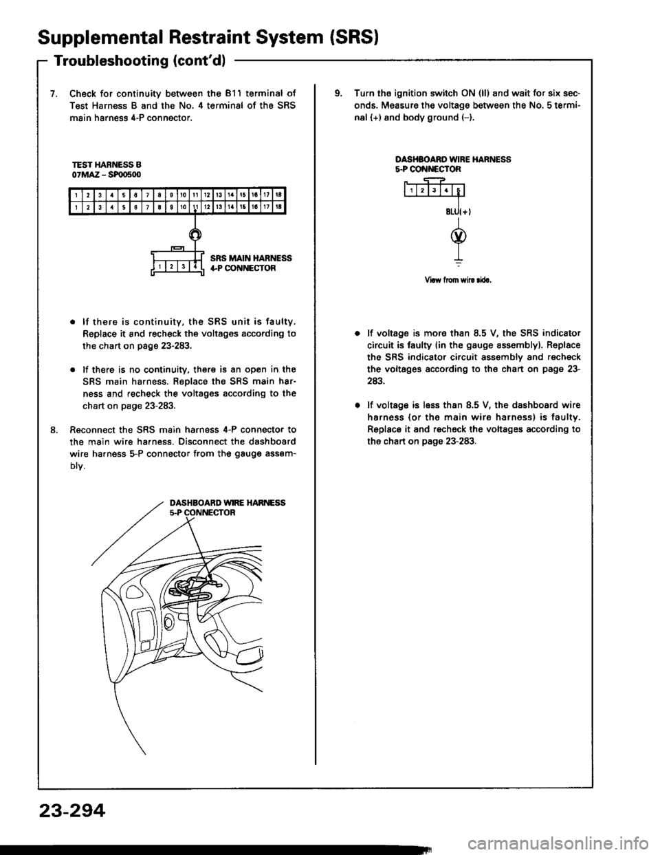
7.Check for continuity between the 811 terminal of
Test Harness B and the No. 4 terminal of the SRS
main harness 4-P conngctor,
oTurn ths ignition switch ON {ll} and wait for six sec-
onds. Measure the voltage between the No. 5 termi-
nal (+) and body ground (-).
TEST HARNESS B07MAZ - SF|D500
OASHSOARO IVIRE HARNESSs.PCO ECTOR
Vraw from sil! rira,
8.
. lf there is continuity, the SRS unit is faulty,
Replace it and recheck the voltages according to
the chart on page 23-283.
. lf there is no cootinuity. there is an open in the
SRS main harness. Replace the SRS main h8r-
ness and recheck the voltages according to the
chart on page 23-283.
Reconnect the SRS main harness 4-P connecto. to
the main wire ha.ness. Disconnect the dashboard
wire ha.ness 5-P connector from the gauge assem-
Dtv.
lf voltage is mora than 8.5 V, the SRS indicator
circuit is faulty (in the gauge assemblyl. Replace
the SRS indicator circuit assembly and recheck
the voltsges according to the chart on page 23-
243.
lf voltage is less than 8.5 V, the dashboard wire
harness (or th€ main wire harness) is faulty.
Replace it and recheck the voltages according to
the chart on page 23-283.
DASHBOARD WIRE HARNESS5.P OONNECTOR
23-294
Page 1401 of 1413
Supplemental Restraint System (SRSI
Airbag Assembly Replacement (cont'd)
3. Remove the airbag(s):
Driver's Side:
. Remove the two TORXo bolts using a TORX0 T30 bit,
then remove the driver's airbag assembly.
DRIVER'SAIRBAG ASSEMBLY
23-296
Front Palsugor'r Sidc:
. Remove the four mounting nuts, then lift the front
passenger's airbag out of the dashboard.
NOTE: Oo not confuse the lower mounting nuts with
the upper mounting nuts. The upper mounting nuts
are not selt-locking.
FRONT PASSENGER'SAIBBAG ASSEMBLY
Page 1402 of 1413
CAUTION: Bo 3uro to in3tsll tho SRS wiring so that it isnot pinchod or intoforing with other car parts.
4. Install the new airbag(s):
Driver's Sido: Place the driver's airbag assembly inthe steering wheel, and secure it with new TORX@bolts.
TORXC BOLT9.8 N'm 11.0 kgt m.7.2lbf.ftl Replace.Uio a TORXO T30 bit
TORXO BOLI9,8 N'm l'1.0 kgf.m,7.2lbtftl Replaco.Us. . TORX6 T30 bit
Front Pa$aogsr's Sid€:
. Place the front passenger's airbag assembly in thedashboard.
Loosely install all four mounting nuts.
Tighten the upper two nuts first, then the lowsr twonuts. Adjust the lower mounting bracket if necessarV.
FRONT PASSENGER'SAIRBAGASSEMALY
UPPERMOUNTING NUTS
LOWERMOUNTING NUTS9.8 N.m (1.0lgtm, t.2lbtftlReolace.
CONNECTORIREDI
{cont'd)
23-297
Page 1403 of 1413

Supplemental Restraint System (SRSI
Airbag Assembly Replacement (cont'd)
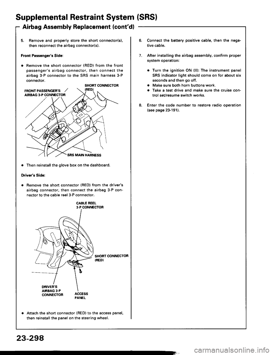
5. Remove and properly store the short connector(s),
then reconnect the airbag connector(s).
Front Pass€ng€r's Side:
. Remove the short connector (RED) from the front
passenger's airbag connector, then connect the
airbag 3-P connector to the SRS main harness 3-P
connector.
. Then reinstall the glove box on the dashboard,
Driver's Side:
Remove the short connector (RED) from the driver's
airbag connector, then connect the airbag 3-P con-
nector to the cable reel 3-P connector.
CABI-E REEL3-P CONNECTOR
SHORT CONNECTORIRED)
DRIVER'SAIRBAG 3.PCONNECTOR
Attach the short connector (RED) to the access panel,
then reinstall the panel on the steering wheel.
SHORT CONNECTOR
FRONT PASSENGER'S ,,'AIRBAG 3.P CONNECTOR
Connect the battery positive cable, then the nega-
tive cable.
After installing the airbag assembly, confirm proper
system operataon:
. Turn the ignition ON (ll): The instrument panel
SRS indicator light should come on for about six
seconds and then go off.
. Make sure both horn buttons work.
a Take a test drive and make sure the cruise con-
trol sevresum€ switch works.
Enter the code number to restore radio oDeration(see page 23-191).
7.
8.
23-294