Page 1073 of 1413
Circuit Diagram
N0.41 l10oAl No.39 {5OAlNo.1317,5A)
MOIATOR
REI.AY
22-5
Page 1094 of 1413

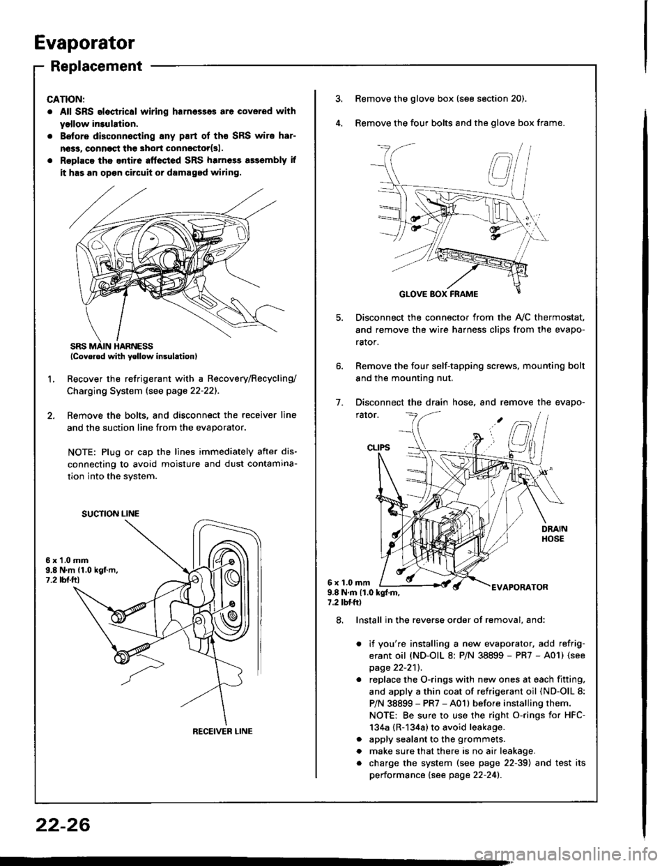
Evaporator
Replacement
CATION:
. All SRS eloctrical wiring harnesses are coverod with
yollow in3ulation.
. B€tore disconnocting 8ny part of tho SRS wire har-
nsss, conngqt th€ 3hort connestor{sl.
. Roplaca ths entire aftected SRS harness a$embly if
it has an op€n circuit or damaged wiring.
lcove.ed with yellow insulation)
Recover the refrigerant with a Recovery/Recycling/
Charging System lsee page 22-22]-.
Femove the bolts, and disconnect the receiver line
and the suction line from the evaporator.
NOTE: Plug or cap the lines immediately after dis-
connecting to avoid moisture and dust contamina-
tion into the svstem.
2.
L
6x1.0mm9.8 N.m {1.019f.m,1.2 tbl.ttl
SUCTION LINE
RECEIVEB LINE
3.Remove the glove box (see section 20).
Remove the four bolts and the glove box frame.
Disconnect the connector from the Ay'C thermostat,
and remove the wire harness clips from the evapo-
rator.
Remove the four self-tapping screws, mounting bolt
and the mounting nut.
Disconnect the drain hose, and remove the evapo-
rator.
1.
6x1.0mmAPORATOR9.8Nm{1.0kg{.m,7.2 tbtft)
a
a
8. Install in the reverse order of removal. and:
it you're installing a new evaporator, add refrig-
erant oil (ND-OIL 8: P/N 38899 - PR7 - A01) (see
page 22-2'll.
replace the O-rings with new ones at each fitting.
and apply a thin coat of refrigerant oil (ND-OlL 8:
P/N 38899 - PR7 - A01l before installing them.
NOTE: Be sure to use the right o-rings for HFC-
134a {R-134a} to avoid leakage.
apply sealant to the grommets.
make sure that there is no air leakage.
charge the system (see page 22-39) and test its
performance (see page 22-241.
22-26
Page 1107 of 1413

Electrical
Special Tools
Troubleshooting
Tips and Precautions ................................ 23-3Five-stop Tloubleshooting ..............,...-..-... Z3-sSchematic Symbols ................................_. 23-6wire Color Cod€s ..................................... 23-6Relay and Control Unit Locations
Engine Compartment .........,............ ... --. 23-7Dsshboard and Door ..,,......................... 23-gDashboard and Floor ............................. 23-t OOuaner Panel .....-.....23-12Connector ldentification and WireHarness Routing ........ 23-i 3
Index to Circuits and Systems
Airbag ............... ...-..-... 2g-26sAir Conditioning ....,.. Section 2lAltelnator ......_.............. 23-99Anti-lock Brake Systsm (ABS) Section 19Automatic Transmission Section 14Battery .............. .......... 23-66Chafging System ........... 23-98rCigalstte Lighter .....................-...-......-..-.. Z3-2O4Cfock ................. ..........23-197rcruise Controf .......--..-... 23-242Distributor .................... 23-87Fan Controls ................. 23-1ogFuel and Emissions ... Section 1i*Fuses
Under-dash Fuse/Relay Box ................... 23-48Undor-hood ABS Fuse/Retay Box ............ 23-51Under-hood Fuse/Relay Box,.................. 23-52rGauges
Engine Coolant Temperature {ECT)Gauge ................ ..23-126Fuef cauge ............... 2g-123'Gauge Assembly ....--.23-113Speedometer .....-...,,. 23-114Tachometer .....,.....-.. 23-114Ground Distribution ........ 23-60Heater ,,,........,.... ..... Section 2lrHorn ................. ........... 23-199*fgnition Switch ............. 23-70fgnition Syst6m .......-..-.. 23-A7lgnition Timing .............. 23-89Indicator Lights"A/T Gear Position .............. ................... 23-1 32B1ak6 System ...,..,..-.23-127Engine Oil Pressura .............................. _ 23-1 51Low Fuel ............ ......23-125Malfunction Indicator Lamp {MlL} ...,,. Section I l
tfnteglated Control Unit ...29-144*lnterlock System ...................................... 23-1 3gLights, Exteriol
Back-up Lights ........... 23-179Brake Lights .............. 23-t8ltDaytime Running Lights {Csnada} ........... 23-156Front Palking Lights ............................. 23-1 65Flont Side Marker Lights ....................... 23-165Front Turn Signal Lights ........................ 23-1 65*Hazard Warning Lights .........................- 2g-1A4Headlights ................. 23-t6tLicense Plate Lights .............................. 23-1 69Taillights(Harchback) .......... 23-166
{Sedan) .............. .. 23-167Lights. Inteliol
Cargo Area Light {Hatchback) ...... -.. -.. -... 23-177Ceifing Light ........-..-.23-175
Dash Lights Blightness Controt .............. 23-t70Glove Box Lighr ................................... 23-1 69Spotfighr ............ ....-.23-174Trunk Light (Sedanl ............... .............. - 23.-177*Lighting Sysrem .......-.-... 23-152:Moonroof ,,.,.......,..,,,,,.-.23-211PGM-FI Systom ........ S€crion 11Power Distribution .,.-..--..23-54Power Door Locks .............,,..................... 23-233Power Mirors ..,..,....-...- 23-216Power Relays ...........,..... 23-68Power Windows ............ 29-222*Rear Window Defogger ........,... ..........,..... - 23-20,6Reminder Systems
Key-in Remindel System ....,.............,.... 23-1 50Lights-on Reminder System ................... 23-l 5f*Maintenance Reminder system ..,,.... -.. - -. 23-.1 2gSeat Belt Reminder System ..................- 23-125*Side Markel/Turn Signal/Hazard
Ffasher System .,..,..-.23.-1A4Spark Pfugs .........-...-..... 23-97Starting System ....,,.....-. 23-73*Stereo Sound System ...,.......................,,.. 23-l gg
Supplemental Restraint System {SRS} ......... 23-265Vehicfe Speed Sensor {VSS) .............--..-.... 23-122*Wiper/Washer Systom ...............--.........-..- Zg-254
rRead SRS pi€cautions on Page 23-271 betore workingin these areas.
-+
Page 1111 of 1413

Five-step Troubleshooting
1. Verify The Complaint
Turn on all the components in the problem circuit to
verify the customer complaint. Note the symptoms.
Do not begin disassembly or testing until you have
narrowed down the Droblem area.
2. Analyze The Schomatic
Look up the schematic for the problem circuit. De-
termine how the circuit is supposed to work by trac-
ing the current paths from the power leed through
the circuit components to ground. It severalcircuits
fail at the same time, the luse or ground is a likely
cause.
Based on the symptoms and your understanding of
the circuit operation, identity one or more possible
causes of the Droblem.
3. lsolato The Problom By Testing The Circuit
Make circuit tests to check the diagnosis you made
in step 2. Keep in mind that a logical, simple proce-
dure is the key to etticient troubleshooting. Test for
the most likely cause of failure first. T.y to make
tests at points that are easilv accessible.
4. Fix The Problem
Once the specilic problem is identified, make therepair. Be sure to use proper tools and safeproceoures.
5. Mak6 Suro The Circuit Wolks
Turn on all components in the repaired circuit in allmodes to make sure you've fixed the entire problem.
It the problem was a blown Juse, be sure to test allof the circuits on thst tuse. Make sure no newproblems turn up and the original problem does not
recuf.
23-5
Page 1112 of 1413

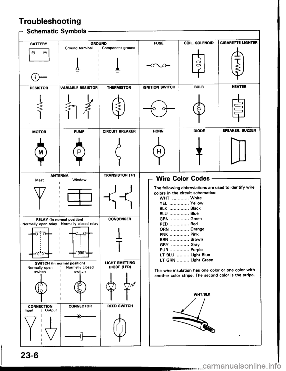
Troubleshooting
Schematic Symbolsym
BATTERY
le @l
ll
e-
GROIGround terminal
I
,ltDComponont ground
I
FUSECOIL, SOLENOID
H
CIGANETTE LIGHTER
A
t+j
RESISTOR
+
VARIABLE RESISTOR
ilH
THERMISTOR
e
tcNtTtol{ swTcH
-1o oF
BULB
e
HEATER
H
MOTOR
a
PUMP
0
CIRCUIT BREA(ER
I
T
HORI'
+
DIODE
+
SPEATER, BUZZER
D
Mast
Y
ANTIINNATRA SISTOR lTrl
II
Wire Golor Codes
The tollowing abbreviations are used to identity wire
colors in th€ circuit schematics:
wHT ............ White
YEL .............. Y6llow
BLK .............. Black
BLU .............. Blue
GRN ............. Green
RED.............. Red
ORN ............. Orange
PNK .............. Pink
BRN .............. Brown
GRY ............. Gray
PUR .............. Purple
LT BLU ......... Light Blue
LT GRN ......... Light Gr€en
The wi.e insulation has one color or one color with
another color stripe. The s€cond color is the stripe.
WHT/ALK
,/t,/l./l--
R
RELAY {ln noNormally open relayrmal poritionl
Normally closed relay
*Gt-i- |
lll
l'*^f
CO'IDENSER
I
T
SWITCH (ln ngrmal position)
Normally open ' Normally closodswitch I switch
til
@@
lil
LIGHT EMITTINGDIODE (LEDI
A[,
TT
CONNEInpur
f7
I
CTIONOutput
I\/
CONNECTON
--+>-
tl'l
BEED SWITCH
A
lril
Y
23-6
Page 1155 of 1413

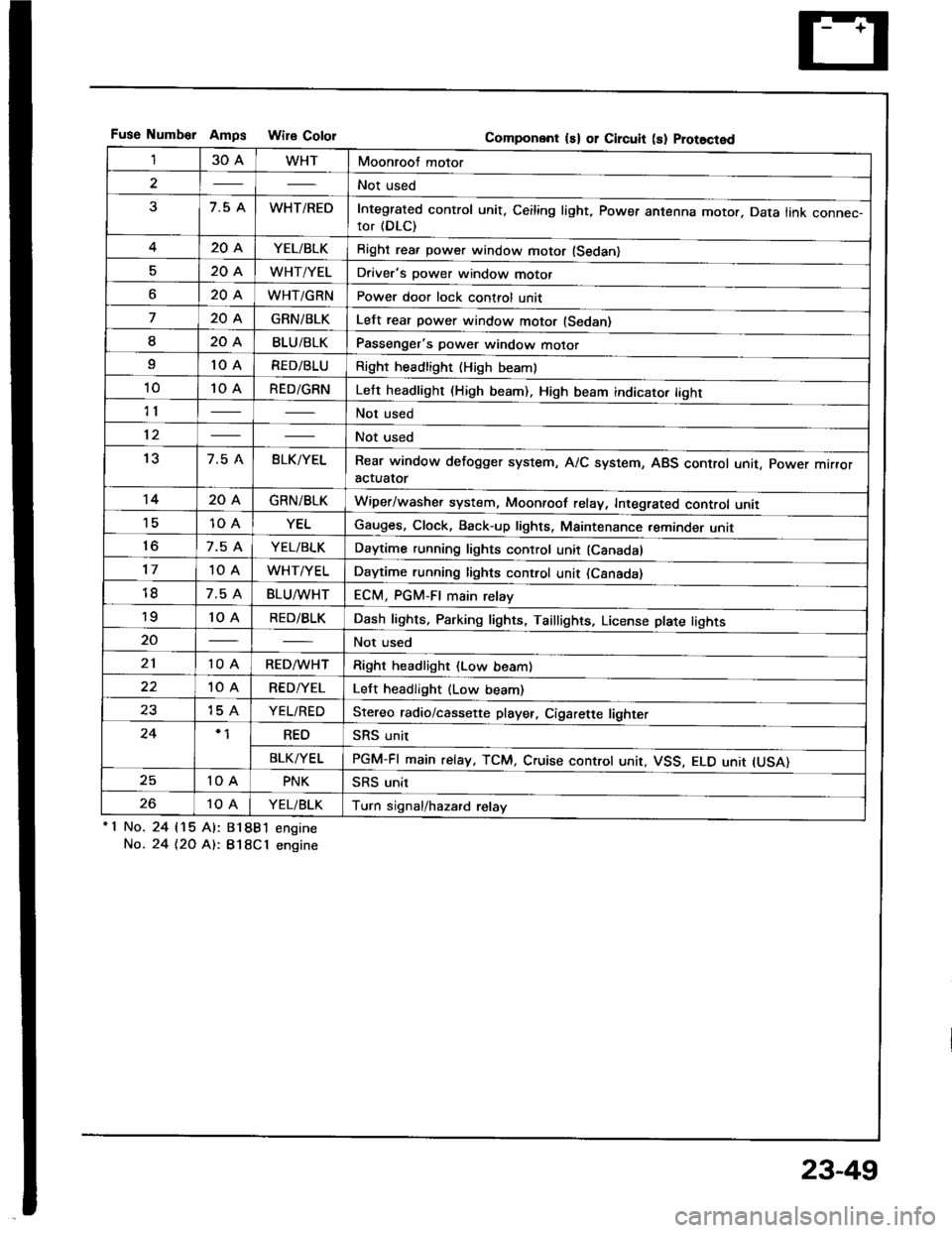
Fuse Numb€r AmDs Wire CololGomponent ls) or Circuit (s) Prot8cted
130AWHTMoonroof motor
2Not used
37.5 AWHT/REDIntegrated control unit, Ceiling light, Power antenna motor. Data link connec-tor (DLC)
420AYEL/BLKRight rea. power window motor (Sedan)
520AWHT/YELDriver's power window motor
o20AWHT/GRNPower door lock control unit
720AGRNiBLKLelt rear power window motor (Sedan)
I20ABLU/BLKPassenger's power window motor
I10 ARED/BLURight headlight {High beaml
1010 ARED/GRNLeft headlight (High beam). High beam indicato. tight
11Not used
12Not used
137.5 ABLK/YELRear window defogger system, A/C system, ABS control unit, power mrrroractuator
1420AGRN/BLKWiper/washer system, Moonroof relay, Integrated control unii'1510 AYELGauges, Clock, Back-up lights, Maintenance reminder unit
to7.5 AYEL/BLKDaytime running lights control unit (Canadal
1710 AWHT/YELDaytime running lights control unit (Csnada)
7.5 ABLU^tvHTECM, PGM-FI main relay'to10 ARED/BLKDash lights, Parking lights, Taillights, License plate tights
20Not used
2110 ARED/WHTRight headlight (Low beam)
10 ARED/YELLeft headlight (Low beam)
2315 AYEL/REDStereo radio/cassette player, Cigarette lighter
24REOSRS unit
BLK/YELPGM-FI main relay, TCM, Cruise controt unit, VSS, ELO unit IUSA)
2510 APNKSRS unit
2610 AYEL/BLKTurn signal/hazard relay'1 No.
No.
24 115 Al:
24 t2O At:.
81881 engine
B18Cl engine
23-49
Page 1157 of 1413
Under-hood ABS Fuse/Relay Box
Wire Color
C9O3 ITo ABS pump molor rolayl
C9O1 [To main wiro ham6$ (C212]l
Componont (s) or Circuit (sl Protectsd
T5 [To undo]-hood ABS fuso/rolay box cabl.l
C9O2 [To moin wiro hs1n6ss (C213]l
ABS 8120AWHT/GRNRight/left ABS front solenoids
ABS 8215 AWHTABS control unit, ABS rear solenoid
ABS MOTOR40AABS pump motor relay, ABS unit (10 A) fuse
ABS UNIT10 ABRN/YELABS control unit
23-51
Page 1162 of 1413
Power Distribution
Circuit ldentification
IGNITION SWITCH
+page 23-
r 1 No.24115A): 81881 engin€No.24 l20A): Bl8C1 6ngin.
N0.40 {504)FUSE(From pago 23 - 551
UNDER - DASH FUSE/REIAY BOX
sRs FusE 81-0cK
No.25l10Al
No.14l20A)
No.l5 {1041
Chuging sY3l.m lightlln tho g6ug€ s3€mblyl
Cruis€ controlunitCdis6 msin 3whch itdicttor light
PGM - Fl mlin r6lry
) lrrmmirdon control modulo [ICM)
Vohag6 rcoulatorVehiclo sp.€d somor IVSS)E|.l) unit IUSA)Crube conttol unit
Moonrcof rclayWind.hicld wipot motorWirdlhi€ld waah6. motorR6ar window ws3hor motot {HrtchblctlInt.gGtod control unit
Power wirdow tclaY
Int6lrat€d contrcl unit- R6af window wipor motol(H3tchbtck)
571
GRNiEI(GRNAt(
GRN/8I..K
BLKffEt
-EiT"h#,H#J:r"
Shitt lock solenoU {MlEack -up lights
option conn€ctor: C924
Daytimo running lights conttol unit
YEt..--
lrcz
Ml t -'-
\'- _ ^ACC
23-56
*2 No.17 {1041bor sockstl