1994 HONDA INTEGRA electrical
[x] Cancel search: electricalPage 639 of 1413

Steering Column
Installation (cont'dl
Finaltorque:22 N.m{2.2 kgf.m, 16lbt.ftl
CAUTION:
. All SRS electrical wiring hrrnossos are covgrod wilhyellow insulation,
. When disconn€cting the SRS wire harness, installthe short connector on the airbag. th€n dbconnoct
the wire harness.
. Replaca the entire alfected SRS harness assembly if
there is an open circuit or damage to tho wiring.
1. Slip the upper end of the steering joint onto the col-
umn shaft {line up the bolt hole with the flat on the
shaft), and loosely install the upper steering joint
bolt.
UPPER STEERING JOINT BOLTBolt must line up withflat on shaft.
STEERINGJOINT
Slip the lower end of the steering joint onto the pin-
ion shaft. Line up the bolt hole with the groove
around the shaft) and loosely jnstallthe lower bolt.
NOTE:
. Be sure that the lower steering joint bolt. is
securely in the groove in the steering gearbox
pinion.
. Before tightening the steering joint bolts, pull on
the sleering joint to make sure that the steeringjoint is fully seated.
LOWER STEERING JOINT BOLTFin6ltoroue:22 N.m {2.2 kgt m. 15 lbf.ftl
17 -32
Install the steering column with the flange nuts,then installthe column holder and flange bolts.
Tighten the upper and lower steering joint boltsloosely installed in steD 2,
FLANGE BOLTS22 N.m12.2 ksi.m, 16 tbtftl
Install the steering joint cover with the clamps andclip.
CLIP
Page 997 of 1413

Front and Rear Consoles
Replacement
SRS wire harnesses are routed near the front console.
CAUTION:
a All SFS electrical wiring harnesses aro coverod
with y6llow insulalion.
a Betore disconnecting any part of lho SRS wire
harness, connect th€ short connoctorc (so€ pago
20-272t.
a Replaco tho sntilo aftocted SRS halness assom-
bly it it has an opon circuit or damaged wlring.
FBONTPASSENGER'S AIRBAG
20-128
NOTE: Take care not to scratch the tront and rear con-
soles, and dashboard.
1. Remove the access cap.
CAUTION: liYhen prying with a flat tip scr€wd.lv€r,
wrap it with protoctivo tape to provent damag€.
ACCESS CAP
2. Remove the sctews.
v : Scraw loc€tlona
At : Scr.w, 2 Bv : Scrow, 2
E)
w)
Page 1039 of 1413
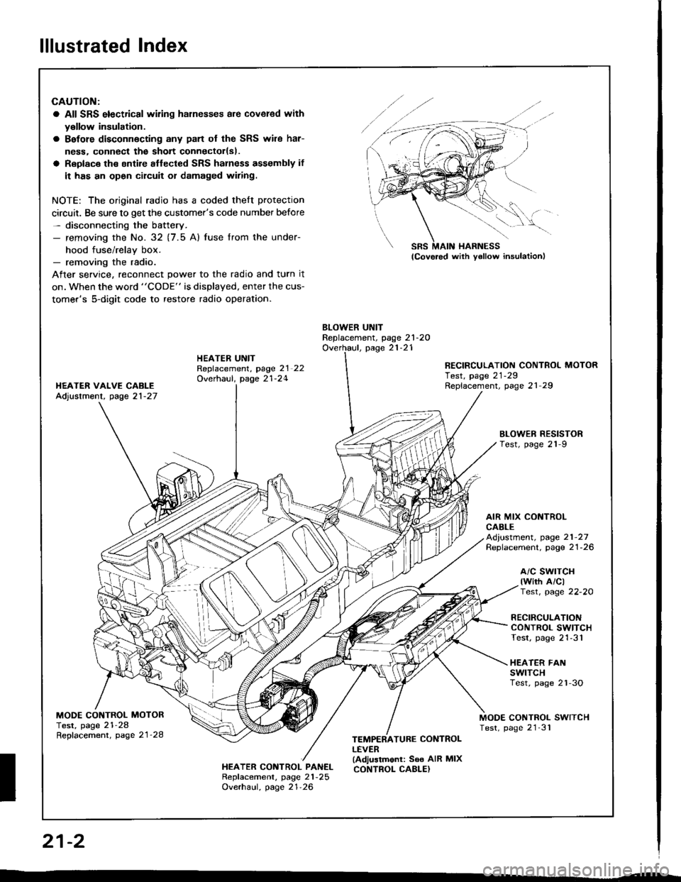
lllustrated Index
CAUTION:
a All SRS electrical wiling harnesses are covered with
y€llow insulation.
a Bafore disconnecting any pan of the SRS wile har-
ness. connect the sholt connectorlsl.
a Replace the sntire aflected SRS halness assembly if
it has an open circuit or damaged wiring.
NOTE: The original radio has a coded thelt protection
circuit. Be sure to get the customer's code number before- disconnecting the battery.- removing the No. 32 (7.5 Al fuse lrom the under-
hood fuse/relav box.- removing the radio.
After service, reconnect power to the radio and turn it
on. when the word "CODE" is displayed, enter the cus-
tomer's 5-digit code to restore radio operation.
BLOWER UNITReplacement, page 21-2OOverhaul, page 21-21HEATER UNITRepfacement, page 2l 22Overhaul, page 21-24
RECIRCULATION CONTROL MOTORTest, page 21-29Replacement, page 21 29I{EATER VAIVE CABLEAdjustment, page 21-27
BLOWEN RESISTORTest, page 21-9
AIR MIX CONTROLCABLEAd,ustment, page 21-27Replacement. page 21-26
a/c swrTcH(wirh A/clTest, page 22-20
RECIRCULATIONCONTROL SWITCHTest, page 21-31
HEATER FANswtTcHTest, page 2'l-3O
MODE CONTROL MOTORTest, page 21-28Repfacement, page 21'28
MODE CONTROL SWITCHTest, page 21'31
HEATER CONTROL PANELRepf acement, page 21 -25
Overhaul, page 21-26
TEMPERATURE CONTROLLEVER(Adjustmonl: See AIR MIXCONTROL CABLE}
SRS MAIN HARNESS
W,
21-2
I
Page 1059 of 1413
Heater Unit
Replacement
CAUTION:
a All SRS electrical witing hame$os are covoed wlth
yollow insulation.
a Before disconnecting any patt of tho SRS wito har-
neas, connect tha shott connoctol(s|.
a Roplaco th€ enlire sffacted SRS harnosr a$smbly if
it has an opon cilcult or dsmaged wiring.
NOTE: The original radio h8s a coded theft protection
circuit. Be sure to get the customer's code number betors
- disconnecting the bafterY.
- removing the No. 32 (7.5 A) fuse from th€ under-
hood tuse/relav box.- removing the radio
After service. teconnect power to the radio and turn it
on, when the word "CODE" is displayed, enter the cus-
tomer's 5-digit code to restore radio operation.
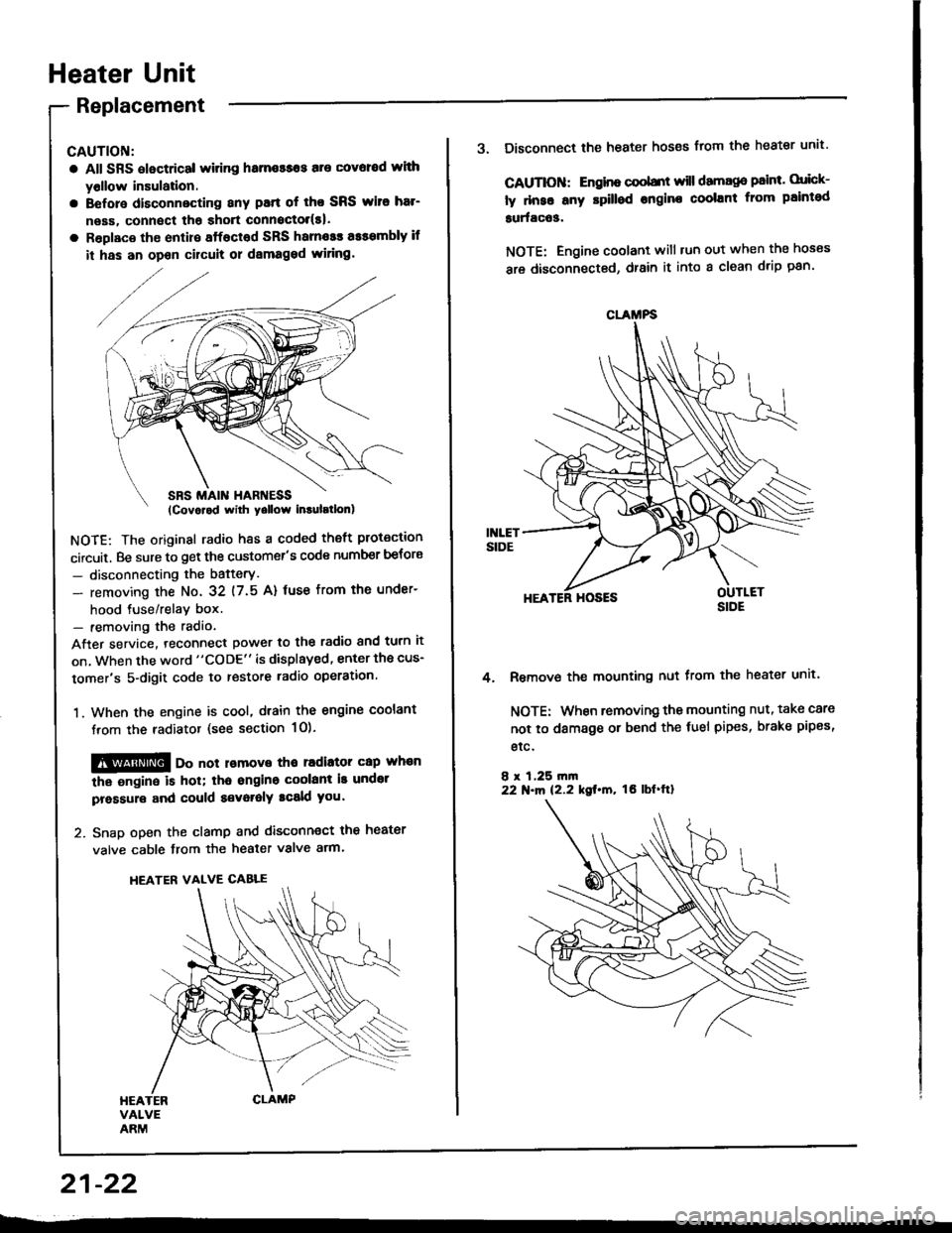
1. When the engine is cool, dtain the engine coolant
from the radiator (see section 1O).
@@ oo not lomove tho radiator cap whan
the ongine is hol; tha ongino coolant is undot
pressure and could a€voralY tcald you.
2. Snap open the clamp and disconnect the heater
valve cable from the heater valve arm.
HEATER VALVE CABLE
21-22
CLAMFS
3. Disconnect the heater hoses from the heater unit'
CAUTIOII: Engino coobnt will damago paint. orick-
ly dnse any rpilled engine coolant from paintod
surfac63.
NOTE: Engine coolant will tun out when the hoses
are disconnected, drain it into a clean drip pan'
HEATER HOSES
Remove the mounting nut from the heater unit.
NOTE: When removing the mounting nut, take care
not to damage or bend the fuel pipes, brake pipes,
etc.
8 r 1,25 rn|n22 N.m 12.2 kgt.m, tO lbf'ftl
4.
Page 1071 of 1413
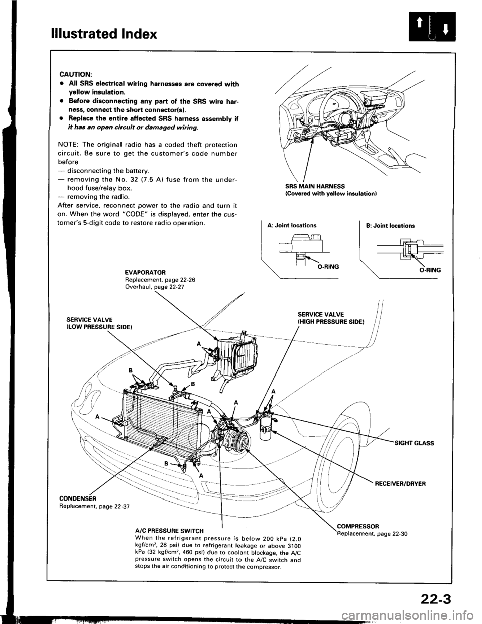
lllustrated Index
CAUTION:
. All SRS electrical wiring harnossos are cover€d withyellow insulation.
. B€fors disconnacting any part of the SRS wire har-ness, connsct the 3hort connsctor(s).. Replace the entirs affscted SRS harness assembly itit has an open circuit or damaged wiring.
NOTE; The original radio has a coded theft protection
circuit. Be sure to get the customer's code number
before- disconnecting the battery.- removing the No.32 (7.5 A) fuse from the under-
hood fuse/relay box.- removing the radio.
After service, reconnect Dower to the radio and turn it
on. When the word "CODE" is displayed, enter the cus-
tomer's 5-digit code to restore radio operation.
SRS MAIN HARNESSlcover€d with yellow insulationl
EVAPORATORReplacement, page 22-26Ovethaul. Oase 22.27
SERVICE VALVE(LOW PRESSURE SIDEI
SERVICE VALVEIHIGH PRESSURE SIDE)
RECEIVER/DRYER
CONDENSERReplacement, page 22,37
A/C PRESSURE SWITCHCOMPRESSORReplacement, page 22-30When the refrigerant pressure is below 200 kpa (2.0kqflcm,,28 psi) due to refrigerant leakage or above 3]OOkPa (32 kgf/cm,, 460 psi) due to coolant btockage, the A,/Cpressure switch opens the circuit to the A"/C switch andstops the air conditionang to protect the compressor.
22-3
Page 1107 of 1413

Electrical
Special Tools
Troubleshooting
Tips and Precautions ................................ 23-3Five-stop Tloubleshooting ..............,...-..-... Z3-sSchematic Symbols ................................_. 23-6wire Color Cod€s ..................................... 23-6Relay and Control Unit Locations
Engine Compartment .........,............ ... --. 23-7Dsshboard and Door ..,,......................... 23-gDashboard and Floor ............................. 23-t OOuaner Panel .....-.....23-12Connector ldentification and WireHarness Routing ........ 23-i 3
Index to Circuits and Systems
Airbag ............... ...-..-... 2g-26sAir Conditioning ....,.. Section 2lAltelnator ......_.............. 23-99Anti-lock Brake Systsm (ABS) Section 19Automatic Transmission Section 14Battery .............. .......... 23-66Chafging System ........... 23-98rCigalstte Lighter .....................-...-......-..-.. Z3-2O4Cfock ................. ..........23-197rcruise Controf .......--..-... 23-242Distributor .................... 23-87Fan Controls ................. 23-1ogFuel and Emissions ... Section 1i*Fuses
Under-dash Fuse/Relay Box ................... 23-48Undor-hood ABS Fuse/Retay Box ............ 23-51Under-hood Fuse/Relay Box,.................. 23-52rGauges
Engine Coolant Temperature {ECT)Gauge ................ ..23-126Fuef cauge ............... 2g-123'Gauge Assembly ....--.23-113Speedometer .....-...,,. 23-114Tachometer .....,.....-.. 23-114Ground Distribution ........ 23-60Heater ,,,........,.... ..... Section 2lrHorn ................. ........... 23-199*fgnition Switch ............. 23-70fgnition Syst6m .......-..-.. 23-A7lgnition Timing .............. 23-89Indicator Lights"A/T Gear Position .............. ................... 23-1 32B1ak6 System ...,..,..-.23-127Engine Oil Pressura .............................. _ 23-1 51Low Fuel ............ ......23-125Malfunction Indicator Lamp {MlL} ...,,. Section I l
tfnteglated Control Unit ...29-144*lnterlock System ...................................... 23-1 3gLights, Exteriol
Back-up Lights ........... 23-179Brake Lights .............. 23-t8ltDaytime Running Lights {Csnada} ........... 23-156Front Palking Lights ............................. 23-1 65Flont Side Marker Lights ....................... 23-165Front Turn Signal Lights ........................ 23-1 65*Hazard Warning Lights .........................- 2g-1A4Headlights ................. 23-t6tLicense Plate Lights .............................. 23-1 69Taillights(Harchback) .......... 23-166
{Sedan) .............. .. 23-167Lights. Inteliol
Cargo Area Light {Hatchback) ...... -.. -.. -... 23-177Ceifing Light ........-..-.23-175
Dash Lights Blightness Controt .............. 23-t70Glove Box Lighr ................................... 23-1 69Spotfighr ............ ....-.23-174Trunk Light (Sedanl ............... .............. - 23.-177*Lighting Sysrem .......-.-... 23-152:Moonroof ,,.,.......,..,,,,,.-.23-211PGM-FI Systom ........ S€crion 11Power Distribution .,.-..--..23-54Power Door Locks .............,,..................... 23-233Power Mirors ..,..,....-...- 23-216Power Relays ...........,..... 23-68Power Windows ............ 29-222*Rear Window Defogger ........,... ..........,..... - 23-20,6Reminder Systems
Key-in Remindel System ....,.............,.... 23-1 50Lights-on Reminder System ................... 23-l 5f*Maintenance Reminder system ..,,.... -.. - -. 23-.1 2gSeat Belt Reminder System ..................- 23-125*Side Markel/Turn Signal/Hazard
Ffasher System .,..,..-.23.-1A4Spark Pfugs .........-...-..... 23-97Starting System ....,,.....-. 23-73*Stereo Sound System ...,.......................,,.. 23-l gg
Supplemental Restraint System {SRS} ......... 23-265Vehicfe Speed Sensor {VSS) .............--..-.... 23-122*Wiper/Washer Systom ...............--.........-..- Zg-254
rRead SRS pi€cautions on Page 23-271 betore workingin these areas.
-+
Page 1110 of 1413
Troubleshooting
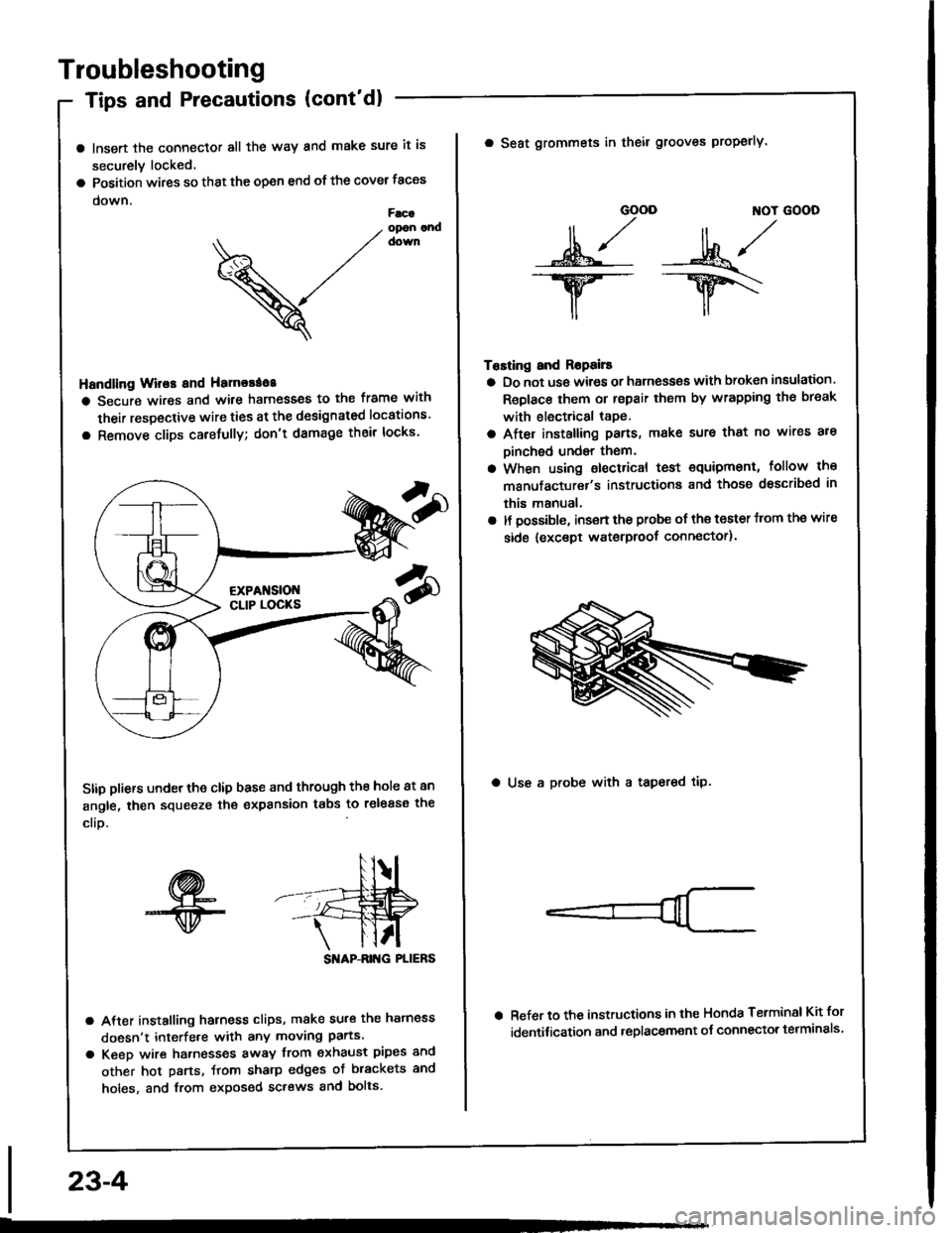
Tips and Precautions (cont'dl
a lnsert the connector all the way and make sure it is
securely locked.
a Position wires so that the open end of the cover taces
down.Facaopon andcown
V
Handling Wir€s and Hamorao8
a Secure wires and wile harnesses to the frame with
their respective wire ties at the designated locations'
a Remove clips carefully; don't damage their locks'
Stip pliers under the clip base and through the hole at an
angle, then squeeze the expansion tabs to release the
clio.
SI'IAP-ANG PLIERS
a After installing harness clips, make su.€ the hatness
doesn't interfe.e with any moving parts.
a Keeo wire hatnesses away from exhaust pipes and
other hot parts, ftom sharp edges of brackets and
holes, and from exposed screws and bolts.
23-4
GOOD ]TOT GOOD
n,/r/ll ,,' ll ,,
s*j -:ut*/-.w-- --ry\
il,,
Tosting and Ropails
a Do not us€ wires or harness€s with broken insulation.
Replace them or repair them by wrapping th€ break
with electrical tape.
a After installing pans, make sure that no wir€s are
Dinched undsr them.
a When using electrical test €quipment, follow the
manufacturer's instructiona and those dsscribed in
this manual,
a It possible, insert the probe of the toster from the wire
side {except waterproof connector).
a Seat grommets in theil grooves properly.
a Use a probe with a tapered tip.
Refer to the instructions in the Honda Terminsl Kit for
identification and .eplacement o{ connector telminals'
Page 1113 of 1413
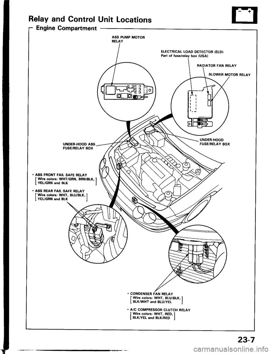
Relay and Control Unit Locations
Engine Compartment
ABS PUMP MOTORRELAY
ELECTRICAL LOAD DETECTOR (ELD)
UNDER.HOODFUSE/RELAY BOXUNOER-HOOD ABSFUSE/BELAY BOX
. ABS FRONT FAIL SAFE RELAY
I Wirc colors: WHT/GRN, BRN/BLK, IIYEL/GRN snd BLK I
. ABS REAR FAIL SAFE RELAY
I Wire colors: WHT, BLU/BLK, II YEL/GRN and BLK I
. CONDENSER FAN RELAY
I Wi]o colors: WHT, BLUi BLK, II BLKMHT and 8LU/YEL I
. A/C COMPRESSOR CLUTCH RELAY
I Wiro colors: WHT, RED, II BLK/YEL and BLK/RED I
23-7