Page 468 of 1413

Electrical Troubleshooting
Troubleshooting Flowchalt (cont'd)
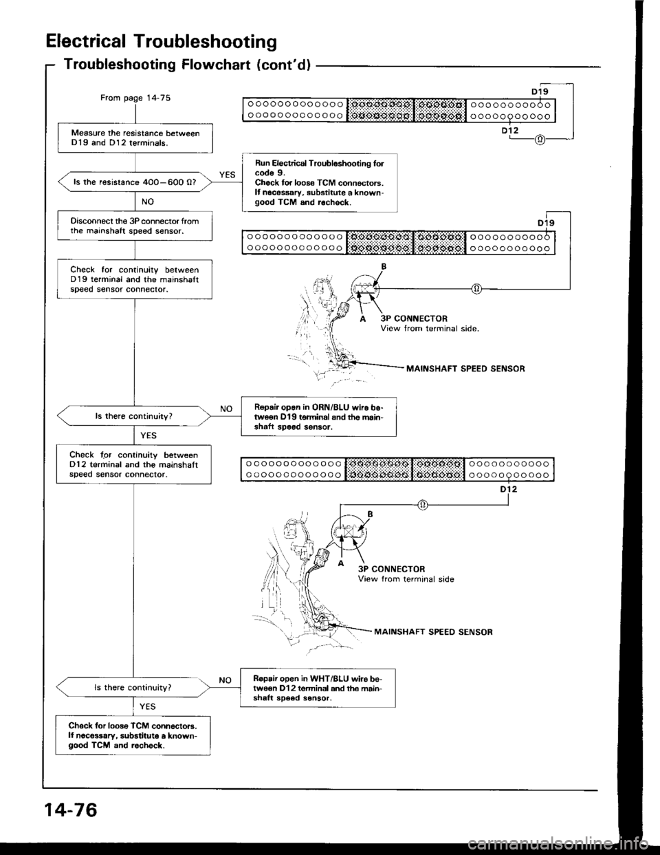
From page 14-75ooooooooooooo
oooooooooooooooooooooooo
ooooooooooo
Measure the resistance betweenD19 and D12 terminals.
Run Electrical Troubleshooting folcode 9.Check for loos6 TCM connectors.It nocessary, substitute a known-good TCM and r.check.
ls the resistance 4O0-600 0?
Disconnecl the 3P connector fromthe mainshaft speed sensor.
Check tor continuitv betweenD19 terminal and the mainshaltspeed sensot connector.
Ropair op.n in ORN/BLU wir6 b6-tweon D19 terminal snd th€ main'shaft spa6d sensor.
Chock tgr continuity betweenD12 terminal and the mainshattspeed sensor connector.
Ropair open in WHT/BLU wire be-twe€n D12 tgrminal and th€ main-shaft sD6ed sonsor.
Chsck for loos€ TCM connoctors.ll noco$ary, substitute a known-good TCM and rocheck.
ooooooooooooo
ooooooooooooooooooooooo
ooooooooooo
ooooooooooooo
ooooooooooooo
ooooooooooo
ooooooooooo
MAINSHAFT SPEED SENSOR
3P CONNECTORView from terminal side
MAINSHAFT SPEED SENSOR
14-76
Page 470 of 1413

Electrical Troubleshooting
Troubleshooting Flowchaft (cont'dl
Does the @ indicatorcome on?
ls there baftery voltage?
YES
lighr
I A25
| | o ooooo o oo o ooo r:sjc.o.sl'1*st,li*os.s.4tcl ooo oo oooooo I
I I o o o o o o o o o o o o q lifrif.S..n${5git:li$gg-:aiiigitll o o o o o o o o o o o I|--.-T..-I a26
+d
+
I + )A23 A25l - l
(+ tA24 426(- |t\@
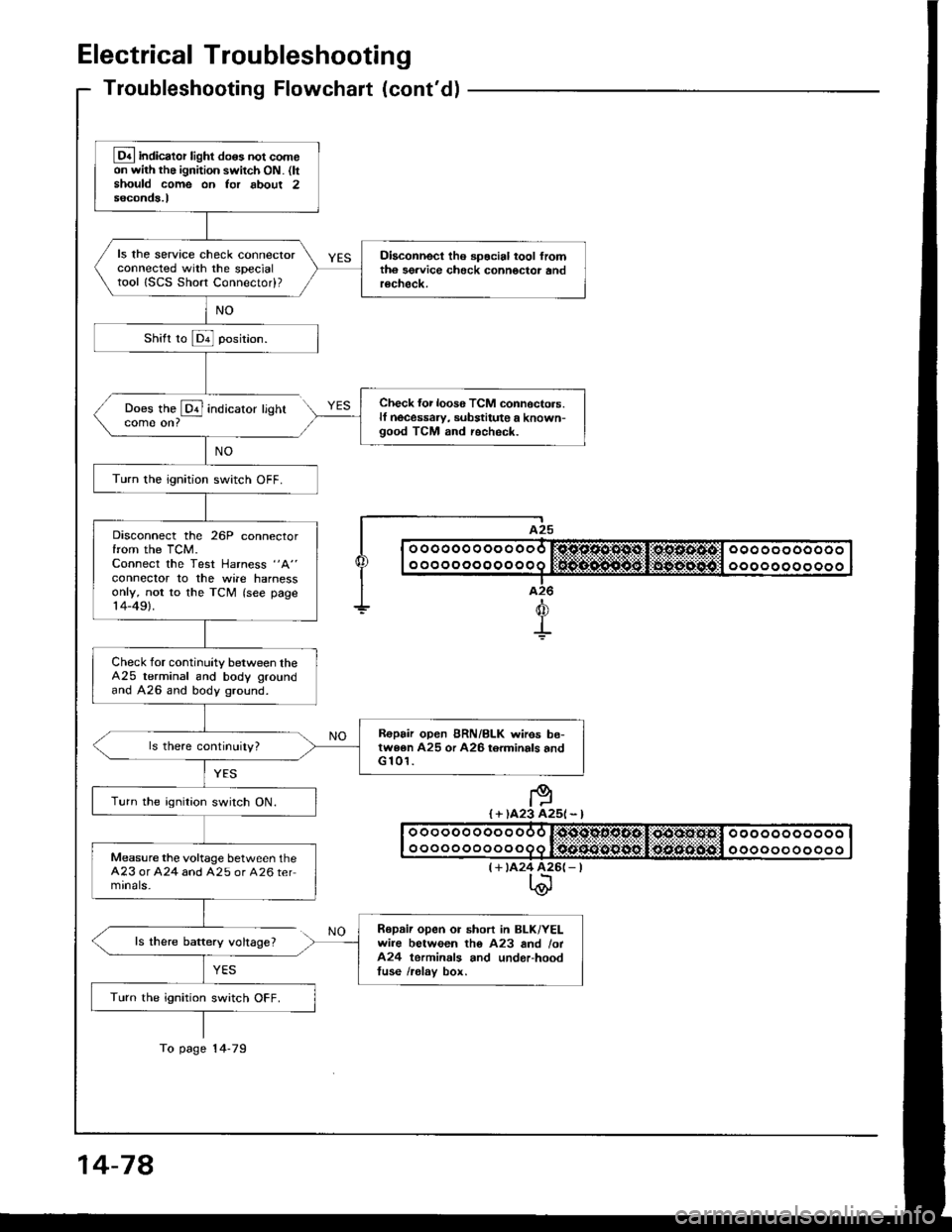
Lq4 indicator light do6s not comeon with the ignition switch ON. (ltshould come on Ior about 2seconds.l
ls the service check connectorconnected with the specialtool ISCS Short Connectod?
Diaconnect tho spocial tool fromth6 sgrvice check connoctor andrecheck.
Check {or loos6 TCM connoctors.lf necessaw, substitute a known-good TCM and recheck.
Turn the ignition switch OFF.
Disconnect the 26P connectorfrom the TCM.Connect the Test Harness "A"
conneclor to the wile harnessonly, not to the TCM (see page14-49).
Check for continuity between theA25 terminal and body groundand A26 and body ground.
R€pair open BRN/BLK wires be-twe6n A25 or A26 torminals andG 101.
Turn the ignition switch ON.
Measure the voltage between theA23 or A24 and A25 or A26 termrnals-
Repaii open or short in BLK/YELwire between tho A23 and /ot424 terminals and underhoodtuse /relav box.
Turn the ignition switch OFF.
To page 14-79
14-78
Page 472 of 1413
Electrical Troubleshooting
Troubleshooting Flowchart {cont'dl
. Lock-up clutch does not haveduty operation (ON -OFF).. Lock-up clutch does not engage.
In3poction ol ths A/C aign6l.
TLrrn the blower switch ON.
Push the A/C switch ON.
Soe Air Condilioning inspoctionlsee rection 221.
Disconnect the 26P conneclorfrom the TCM.
Measure the voltage between theA22 {BLK/RED) and A25 (8RN/
BLKI or A26 IBRN/BLK) terminals.(A/C compressor OFFI
Repair opon in 8LK/RED wiio b6-twoon lho A22 torminal and A/Ccomprossor clulch rel6y.
. A/C aignal ls OK.. Chock lor looso TCM connec-toB. lf n6co$ary, substitute aknown-good TCM and rschock.. Inrpoct tho 6ir condhioning lsooloction 221.
BR /ALK
Page 476 of 1413
Transmission Control Module
Replacement
I The Transmission Control Module (TCMI is located be-
low the dashboard, behind the lelt side kick panel on
the driver's side.
CAUTION:
a All SRS electrical wiring hahesses are covered withyellow insulation.
a Betore disconnecting any pan ot the SRS wile har-
ness. connect the short connectors lsee page 23-7O).
a Replace the entir6 affected SRS harness ass€mbly if
it has an open circuit or damaged wiring.
1. Remove two clips securing the kick panel then
move it.
2. Disconnect the connectors and remove the TCM.
6 x 1.0 mm12 N'm{1.2 kgf.m,8.7 tbf.Itl
WIRE HARNESS/CONNECTORS6 x 1.0 mm12 N.m(1.2 kgf.m, 8.7 lbt.ftl
KICK PANEL
SRS MAIN HARNESS
14-84
Page 560 of 1413

shift cable
Removal/lnstallation
a All SRS electrical wiring hamosses are covor€d withyellow insulation.
a Before disconnecting any pan ot th€ SRS wire har-noss, connect the short connectorc (soe page 23-7O1.a Roplace th€ entiro attect€d SRS haness assembly itit has an open circuit ot damaged wi.ing.
@@[ uar" sul€ litts are placed proparty {so6
section 1).
1. Remove the center console {see section 20).
2. Shift to N position. then remove the lock pin from
the cable adjuster.
@J^ll
AJUI[qJ ]l tl---l
LOCK NUT7 N.m(O.7 kgf.m, 5 lbf.ft)
14-170
3. Remove the shift cable bracket.
6x1.0mm12 N.m 11.2 kgf.m,4.7 lbf.ftl
4. Remove the shitt cable holder.
5. Remove the shift cable cover.
6. Remove the control lever from the control shaft, then
remove the shift cable. Take care not to bend the
cable when removing/installing it.
SHIFT CABLE I{OLDER
Install the shift cable in the reverse orde. of removal.
Check the cable adjustment on reassembly, on page
14-171.
7.
8.
12 N.m 11.2 kgf.rh, 8.7 lbf.ftl
14 N.m 11.4 kgl.m, 10lbt.ft)
Page 561 of 1413

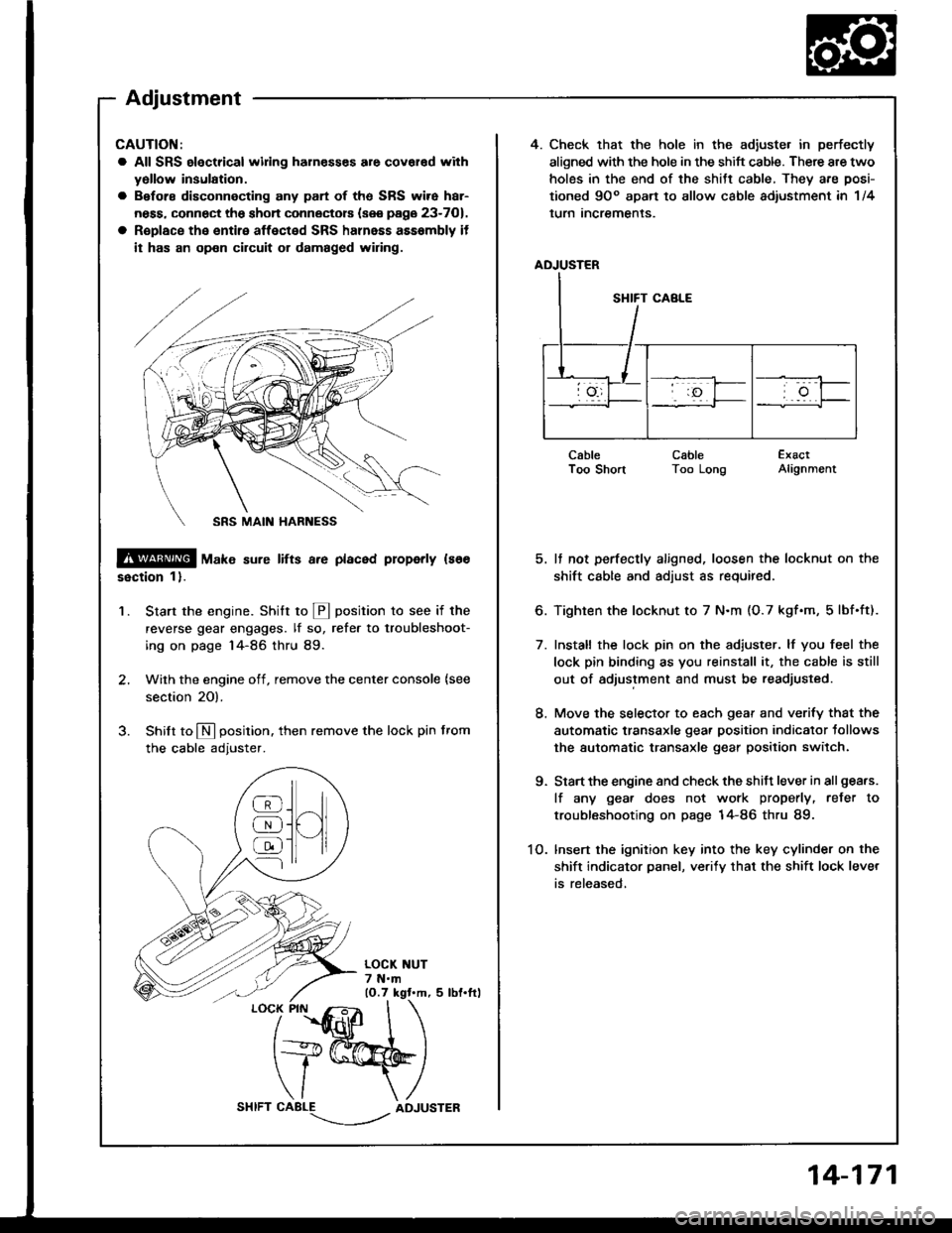
4. Check that the hole in the adiuste. in perfectly
aligned with the hole in the shift cable. There are two
holes in the end of the shitt cable, They are posi-
tioned 9Oo apart to allow cable adiustment in 1/4
lurn Incremenls.
ADJUSTER
CableI oo snonCableToo LongExactAlignment
5. It not perfectly aligned, loosen the locknut on the
shift cable and adjust as required.
6. Tighten the locknut to 7 N.m (O.7 kgf.m, 5lbf.ft).
7. Install the lock pin on the adiuster. lf you feel the
lock pin binding as you reinstall it, the cable is still
out of adjustment and must be readjusted.
8. Move the selector to each gear and verify that the
automatic transaxle gear position indicator tollows
the automatic transaxle gear position switch.
9. Start the engine and check the shift lever in all gea.s.
lf any gea. does not work properly, refer to
troubleshooting on page 14-86 thru 89.
1O. lnsert the ignition key into the key cylinder on the
shift indicator panel, ve.ify that the shift lock lever
is released,
CAUTION:
a All SRS electrical widng harn€sses are covar€d with
yollow insulation.
a Before disconnecting any part of ths SRS wire har-
ness, connect the shon connectors (see page 23-701.
a R€place the entire affected SRS halnass asssmbly it
it has an op€n circuit or damaged wiring.
@ tu"t" sure lifts a.e placed properly ls66
ssction 1).
Start the engine. Stritt to @ position to see if the
reverse gear engages. lf so, refer to troubleshoot-
ing on page 14-86 thru 89.
Wilh the engine off, remove the center console {see
section 20).
Shilt to N position. then remove the lock pin from
the cable adjuster.
'1.
/
''fidlfr
I
t+@
\/ \
CABLE-.'.-_--l../ADJUSTER
]H
@
@
@
Adjustment
14-171
Page 562 of 1413
Gearshift Selector
Disassembly/Reassembly
CAUTION:
a All SRS electrical wiing haln€ssss are covered withy6llow insulation.
a 8€fore disconnecting 8ny pan of the SRS wire har-
neaa. connOct th6 short connectors (sse page 23-701.
a Roplace the entire affected SRS hahess assembly if
il has an opon circuit or damaged wiring.
9.8 N.m {1.O kgf.m, 7.2 lbf.frl
SHIFT LOCK SOLENOID
CONTROL BRACKET
SELECT LEVER BRACKET
CONTROL SEAL
SRS MAIN HARNESS
[E--__ rocK ptN
ADJUSTER
-6{stLtcoNEGREASEe-LEVER COVER
LOCK PIN ROD
-#qSILICONE GREASE
@6
5 N.m (0.5 kgt.m, 4 lbt.ftl
AUTOMATIC TRANSAXLEGEAR POSITION SWITCHTesting, see Section 23
9.8 N.m (1.0
7 .2 tbt.ltl
12 N.m (1.2 kgf.m, 8.7 lbf.ftl
9.8 N.m 11.0 kgf'm,7.2 lbf.ftl
14-172
Page 631 of 1413
Steering Wheel
Removal
Airbag Removal
CAUTION:
. All SRS electrical wiring harnosses are covered with
yellow insulation.
. Before disconnecting any part oI the SRS wiro har-
ness, connect the 3hort connector{g}.
. Replace the entire sffected SRS harness assembly it
it has an opon circuit or damaged wiring.
17-24
1.
AIRBAGCONNECTOR
CABLE REELCONNECTOR
Disconnect the negative and positive cable from the
battery.
Remove the access panel from the steering wheel
lower cover, then remove the shon connector.
Disconnect the connector between the airbag and
cable reel.
Connect the shon connector to the airbag side of
the connector.
Remove the lid B and cruise control set/resume
switch cover.
Remove the TORX@ T30 bit bolts then remove the
airbag assembly.
AIRBAG ASSEMBLY