Page 1272 of 1413
-
Taillights (Hatchbackl
Replacement
23-166
1.Open the resr hatch.
Remove the rear panellining and the side lining {see
section 20).
Disconnect the 4-P connector from the taillight.
Remove the six mounting nuts, then pull out the
taillight.
4.
NOTE:
a Inspect the gasket. Replace it if it is distorted or
stavs compresseo.
a After installation. run wate. over ths lights to
make sure thev don't leak.
4-P CON[{ECTOR
BulbReplacement
R6ei tum slgnal/Rolr parking lights:
1 . Open the rear hatch, then remove the access panel.
2. Remove the bulb lrom the bulb socket.
@: REAR TURN SIGNAL LIGHT BULB (32 CPI
@: REAR PARKING LIGHT BULB {3 CP)
Brake/T8illight/Back-up lights:
1. ODen the rear hatch.
2. Remove the rear panel lining {see section 20).
BACK-UP LIGHT BULB {32 CP}
ERAKE/TAILLIGHT BULB (32l3 CP)
o:
@:
ACCESS PANEL
Page 1274 of 1413
Taillights (Sedanl
Bulb Replacement
Tsillight:
1. Open the trunk lid. then remove the rear panel lin-
ing and side lining {see section 20}.
2. Remove the bulb from the bulb socket.
lnnor T.illlght:
1. Open the trunk lid, then remove the bulb housing.
2. Remove the bulb from the bulb housing.
@:
@:
@:
BRAKE/TAILLIGHT BULB (32l3 CP}
TURN SIGNAL LIGHT BULB (32 CP}
REAR PARKING LIGHT BULB {3 CP)
O:
@:
BACK-UP LIGHT BULB (32 CP}
BRAKE/TAILLIGHT BULB I3213 CP}
BULB HOUSII{G
23-168
l'r'qn'F',
Page 1290 of 1413
Side Marker/TurnSignal/Hazard Flasher System
Component LocationIndex
23-184
GAUTION:
a All SRS electrical wiring harnessos ar6 covered with
yellow insulation.
a Belor€ disconnocting any pan of the SRS wire har-
ngss, connoct the short connector{s).
a Rsplace tho 6ntir€ affect€d SRS harnoss sssembly il
it has an op€n cilcuit or damaged widng.
TURN SIGNAL INDICATOR LIGHTS(ln the gauge assembly)
SRS MAIN HARI{ESS(Cov.rod with Ysllow in3ulationl
Bulb Locations,23-115
COMBINATION LIGHT SWITCHReplacement, page 23-160HAZARD WARI{ING SWITCHReplacement, page 23-187Test, page 23-187
Test, page 23-1
UNDER-DASHFUSE/RELAY 8OX
TURN SIGNAL/HAZARO RELAYInput Test, page 23-186
-
Page 1292 of 1413

Side Marker/Turn Signal/Hazard Flasher System
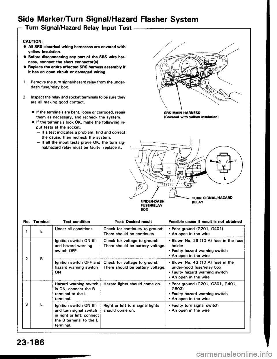
Turn Signal/Hazard Relay Input Test
CAUTION:
a All SRS electrical wiring harn6ss6s ar€ covered with
yellow insulation.
a B€foro disconn6cting any part of th€ SRS wire har-
noss, connoct tho short connector(s).
a Replaco tho ontiro sftoctod SRS harness ass€mbly it
it has an open circuit or damagod wiring,
I . Remove the turn signal/hazard relay from ths under-
dash Juse/relay box.
2. Inspect the relay and socket terminals to be sure they
are all making good contact.
a It the terminals are bent, loose or coroded, repair
them as necessary, and recheck the system.
a lf the terminals look OK, make the tollowing in-
put tests at the socket.- lf a test indicates a problem, find and correct
the cause, then recheck the system.- lf all the input tests prove OK, the turn sig-
nal/hazard relay must be taulty; replace it.
UI{DEB-DASHFUSE/RELAYBOX
Test: D€sired rosult
SBS MAIN HAR ESS{Covg.ed with yollow inrulltion)
TelminalTeEt conditionPo$iblo causo it fosult is not obtainod
,lEUnder all conditionsCheck for continuity to ground:
There should be continuitv.
. Poor ground (G201 , G4O1). An oDen in the wire
2B
lgnition switch ON (ll)
and hazard warning
switch OFF
Check for voltage to ground:
There should be battery voltage.
Blown No. 26 (10 A) fuse in ths fuse
holder
Faulty hazard warning switch
An open in the wire
lgnition switch OFF and
hazard warning switch
ON
Check for voltage to ground:
There should be battery voltage.
Blown No. 43 (10 Al fuse in the
under-hood fuse/relay box
Faulty hazard warning switch
An ooen in the wire
3
Hazard wa.ning switch
is ON; connect the B
terminal to the L
termrnat.
Hazard lights should come on.Poor ground (G2O1, G3O1, G4O1
G503)
Faulty hazard warning switch
An open in the wire
lgnition switch ON (lll
and turn signal switch
in right or left; connect
the B terminal to the L
terminal.
Right or left turn signal lights
should come on.
. Faulty turn signal switch. An open in the wire
23-186
-
Page 1312 of 1413
Rear Window Defogger
Component Location Index
CAUTION:
a All SRS olectrical wi ng ham€$6s are covoled with
y€llow insulation.
B6foro disconnocting any part of ths SRS wire har-
ness. connoct tho short connector(s).
Roplacs the ontire affectod SRS harness assombly if
it has an open circuit or damagcd wiring.
REAB WINDOWDEFOGGER RELAYTest, page 23-68
REAR WINDOWDEFOGGER SWITCHRemoval, page 23-209Test, page 23-2Og
REAR WINDOW DEFOGGERTest, page 23-210
UI{DER.DASH FUSE/RELAY BOX
REAR WINDOW DEFOGGER TIMER CIRCUIT
{ln the integrated control unil)fnput Test, page 23-147
SRS MAII{ HAR'{ESS
The rear window defogger is controlled by the integrated control unit, Pushing the defogger switch in the instrument
panel it sends a signal to the defogger time. in the integrated control unit, and the detogger stays on tor 25 minutes
or until the ignition switch is turned off. The indicator light in the switch comes on when the deJogger works.
23-206