1994 HONDA INTEGRA turn signal
[x] Cancel search: turn signalPage 428 of 1413

Description
Hydraulic Flow (cont'd)
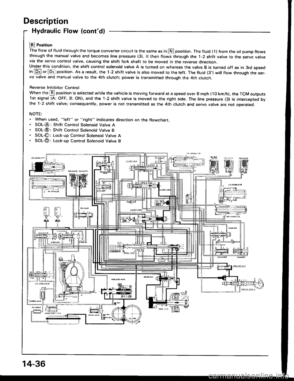
LEI Position
The flow ot fluid through the torque convener circuit is the same as in S position. The tluid ( 1 ) trom the oil pump flowsthrough the manual valve and becomes line pressure (31. lt then flows through the 1-2 shift valve to the servo varvevia the servo control valve, causing the shift tork shatt to be moved in the reverse direction.Under this condition, the shift control solenoid valve A is turned on whereas the valve B is turned ofJ as in 3rd speedin [Dil or lDs]l position. As a result, the 1-2 shift valve is also moved to the left. The ftuid (3'] will ftow through the ser-vo valve and manual valve to the 4th clutch; power is transmitted through the 4th clutch.
Reverse Inhibitor Control
When the @ position is selected while the vehicle is moving forward at a speed over 6 mph ( 1O km/h). the TCM outputs1st signal (A: OFF, B: ON), and the 1-2 shift valve is moved to the right side. The line pressure {3) is intercepted bvthe 1-2 shift valve; consequently, power is not transmitted as the 4th clutch and servo valve are not oDerareo.
NOTE:. When used, "lefl" ot "tight" indicates direction on the flowchart.. SOL-@: Shift Control Solenoid Valve A. SOL€: Shift Control Solenoid Valve B. SOL€: Lock-up Control Solenoid Vatve A. SOL-@: Lock-up Control Sotenoid Vatve B
14-36
Page 443 of 1413

Number of @indicator light
blinks while
Service Check
Connector is
connected with
the special tool.
@ indicator
lightPossible CauseSymptomRefer to
page
'loBlinksDisconnected engine coolant tempera-
rure (ECT) sensor connector
Short or open in ECT sensor wire
Faulty ECT sensor
Lock-up clutch does not
engage.14-68
1lOFFDisconnected ignition coil connector
Short or open in ignition coil wire
Faulty ignition coil
. Lock-up clutch does not
engage.'t 4-7 0
13Blinks. Shon or open in LT GRN wire between
the D3 terminal and ECM. Faulty barometric pressure {BARO)
sensor
NOTE: The BARO sensor is built into
the ECM
. No specific symptom
appears.
14-7 1
14Blinks. Short of open in FAS {YEL} wire be-
tween the D16 terminal and ECM. Faulty ECM
. Transmission jerks hard
when shitting.
't5OFFDisconnected mainshaft speed sensor
connecror
Short or open in mainshaft speed sen-
sor wire
Faulty mainshaft speed sensor
. Transmission jerks hard
when shifting.
14-75
SymptomProbable CauseRet.page
LQ! indicator light is on steady, not blinking whenever the ignition is on.14-77
[Q3] indicator light does not come on for 2 seconds after ignition is first
turned on.14-78
Lock-up clutch does not have duty operation (ON-OFFI.Check A/C signal with
A/C on.14-80Lock-up clutch does not engage.
Shitt leve. cannot be moved lrom @ position with the brake pedal
depressed.Check brake switch signal,14-41
It the self-diagnosis LQ4 indicator light does not blink, perform an inspection according to the table below.
a lf a customer describes the symptoms for codes 3, (yet the LQ! indicator light is not blinkingl, 6, 1 1 or 15, it will
be necessa.y to recreate the symptom by test driving. and then checking the @ indicator light with the ignition still
oN.
e lt ttre @ indicator light displays codes olher than those listed above or stays lit continuously, the TCM is faulty.. Sometimes the Lqd indicator light and the Malfunction Indicator Lamp (MlL)/Check Engine light may come on simul-taneously. lf so, check the PGM-Fl system according to the numbe. of blinks on the MIL/Check Engine light. thenreset the memory by removing the BACK UP fuse in the unde.-hood fuse/relay box for more than 1O seconds. Drive
the vehicle for several minutes at speed over 30 mph (5O km/h), then recheck the MIL/Check Engine light.
NOTE:
. PGM-FI system
The PGM-Fl system on this model is a sequential multiport fuel injection system.a Disconnecting the BACK UP luse also cancels the radio anti-theft code. preset stations and the clock setting. Get
the fuse so vou can reset them.the customer's code number and make note ot the radio
14-51
Page 635 of 1413

Steering Golumn
Removal
LOWER COVER
Remove the column covers
screws.
CAUTION:
. All SRS el€ctrical wiring hlrnesses are coversd withyollow insuhtion.
. Bctore dieconnocting any part ol tho SRS wiro h!r-
nesa, connoct the thort connector (s).
. Roplace tho ontire aftected SRS harness asr€mbly if
it has !n open circuit or d!mlgod wiring.
Remove the airbag assembly and steering wheel
.(see page 17-25).
Remove the lower cover.
Remove the driver's knee bolster.
by re mov in g the
17-2A
scREws
5. Remove the connector holder and disconnect the
SRS main harness from the cable reel wire ha.ness
at the under side ot the column bracket.
HARNESS
Remove the cable reel and turn signal canceling
steeve.
Remove the combination switch from the steering
column by disconnecting the connectors,
TURN SIGNAL CANCELINGSlTEVE
COMA|NANON SW]TCH
7.
CABI..E REEL
STEERING COLUMN
Page 640 of 1413

7.
Connect the ignition switch wire connectors to the
under-dash fuse/relav box.
Install the combination switch and turn signal can-
celing sleeve onto the steering column.
NOTE: Be sure the wires are not caught or pinched
by any parts when installing the combination
switch.
TURN SIGNAL CANCELINGSLEEVE
Install the cable reel onto the steering column, then
connect the SRS main harness and cable reel wiro
harness and install the connector holder.
NOTE: Align the slot in the cable reel with the pro-
jection on the canceling sleeve.
coMatNATroN swncH
UPPER COLUMN COVER
9. Installthe column covers.
scREws
lnstall the driver's knee bolster.
lnstall the lower cover.
Installthe steering wheel {see page '17-26).
10.
11.
't2.
17-33
Page 1008 of 1413

Bumpers
Front Bumper Replacement
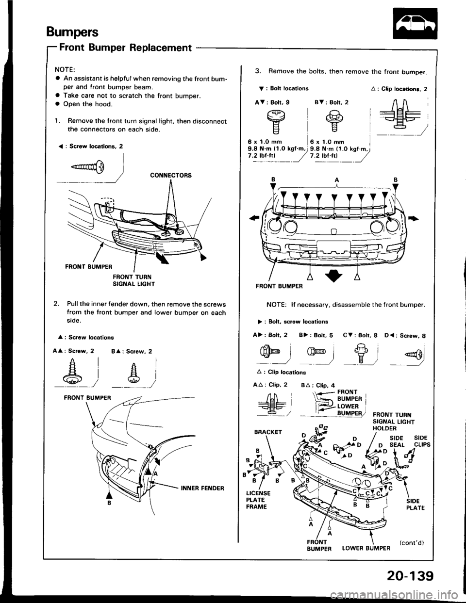
NOTE:
a An assistant is helpful when removing the front bum-per and lront bumper beam.
a Take care not to scratch the front bumper.a Open the hood.
1. Remove the tront turn signal light, then disconnect
the connectors on each side.
< : Sci6w locatlons, 2
FNONT TURNSIGNAL LIGHT
2. Pull the inner fender down. then remove the screws
from the front bumper and lower bumper on each
5rcte.
: Scr6w locations
A : Scrow, 2 BA: Scrow, 2
_A_, __s_,
CONNECTORS
V : Bolt locations
AV: Boh, I BV: Bolr, 2
3. Remove the bolts, then remove the front bumoer.
: Clip locadrn., 2
AA
+Et=-+EP_
:
FRONT BUMPER
NOTE: lf necessary, disassemble the tront bumper.
> : Boll, screw locations
A>: 8olt, 2 8>: Bolr, 5 CV: Bolr, I D<: Screw, 8
nolt
gD
Et2"'l-eo
q-l -ry-l _9, =g
A : Clip locarions
AA : Clip, 2 BA : Ctip, 4
FRONT TURNSIGNAL LIGHTHOLOER
/H i-<€L9- I'a- /
{-r-- FRONT
*= BUMPER r
__tr:i!uF&,
LOWER BUMPER
/ sroe stoE
/ D SEAL CLIPS
fr:**M
INNER FEl{DER
BUMPER
20-139
Page 1033 of 1413

Rear Emblems
lnstallation
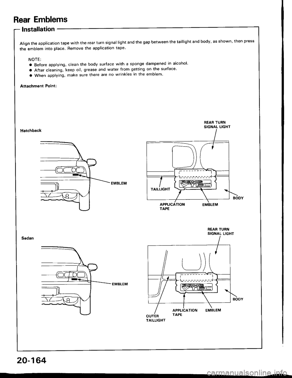
Align the applicalion tape with the rear turn signal light and the gap between the taillight and body, as shown, then press
the emblem into place. Remove the applicataon tape'
NOTE:
a Before applying, clean the body surlace with a sponge dampened in alcohol'
a After cleaning, keep oil, grease and water from getting on the surface'
a When applying, make sure there are no wrinkles in the emblem'
Attachment Point:
REAR TURNSIGNAL LIGHTHatchback
REAR TURNSIGNAL LIGHT
20-164
!---_-----------,-i-J
TAILLIGHT
Page 1107 of 1413

Electrical
Special Tools
Troubleshooting
Tips and Precautions ................................ 23-3Five-stop Tloubleshooting ..............,...-..-... Z3-sSchematic Symbols ................................_. 23-6wire Color Cod€s ..................................... 23-6Relay and Control Unit Locations
Engine Compartment .........,............ ... --. 23-7Dsshboard and Door ..,,......................... 23-gDashboard and Floor ............................. 23-t OOuaner Panel .....-.....23-12Connector ldentification and WireHarness Routing ........ 23-i 3
Index to Circuits and Systems
Airbag ............... ...-..-... 2g-26sAir Conditioning ....,.. Section 2lAltelnator ......_.............. 23-99Anti-lock Brake Systsm (ABS) Section 19Automatic Transmission Section 14Battery .............. .......... 23-66Chafging System ........... 23-98rCigalstte Lighter .....................-...-......-..-.. Z3-2O4Cfock ................. ..........23-197rcruise Controf .......--..-... 23-242Distributor .................... 23-87Fan Controls ................. 23-1ogFuel and Emissions ... Section 1i*Fuses
Under-dash Fuse/Relay Box ................... 23-48Undor-hood ABS Fuse/Retay Box ............ 23-51Under-hood Fuse/Relay Box,.................. 23-52rGauges
Engine Coolant Temperature {ECT)Gauge ................ ..23-126Fuef cauge ............... 2g-123'Gauge Assembly ....--.23-113Speedometer .....-...,,. 23-114Tachometer .....,.....-.. 23-114Ground Distribution ........ 23-60Heater ,,,........,.... ..... Section 2lrHorn ................. ........... 23-199*fgnition Switch ............. 23-70fgnition Syst6m .......-..-.. 23-A7lgnition Timing .............. 23-89Indicator Lights"A/T Gear Position .............. ................... 23-1 32B1ak6 System ...,..,..-.23-127Engine Oil Pressura .............................. _ 23-1 51Low Fuel ............ ......23-125Malfunction Indicator Lamp {MlL} ...,,. Section I l
tfnteglated Control Unit ...29-144*lnterlock System ...................................... 23-1 3gLights, Exteriol
Back-up Lights ........... 23-179Brake Lights .............. 23-t8ltDaytime Running Lights {Csnada} ........... 23-156Front Palking Lights ............................. 23-1 65Flont Side Marker Lights ....................... 23-165Front Turn Signal Lights ........................ 23-1 65*Hazard Warning Lights .........................- 2g-1A4Headlights ................. 23-t6tLicense Plate Lights .............................. 23-1 69Taillights(Harchback) .......... 23-166
{Sedan) .............. .. 23-167Lights. Inteliol
Cargo Area Light {Hatchback) ...... -.. -.. -... 23-177Ceifing Light ........-..-.23-175
Dash Lights Blightness Controt .............. 23-t70Glove Box Lighr ................................... 23-1 69Spotfighr ............ ....-.23-174Trunk Light (Sedanl ............... .............. - 23.-177*Lighting Sysrem .......-.-... 23-152:Moonroof ,,.,.......,..,,,,,.-.23-211PGM-FI Systom ........ S€crion 11Power Distribution .,.-..--..23-54Power Door Locks .............,,..................... 23-233Power Mirors ..,..,....-...- 23-216Power Relays ...........,..... 23-68Power Windows ............ 29-222*Rear Window Defogger ........,... ..........,..... - 23-20,6Reminder Systems
Key-in Remindel System ....,.............,.... 23-1 50Lights-on Reminder System ................... 23-l 5f*Maintenance Reminder system ..,,.... -.. - -. 23-.1 2gSeat Belt Reminder System ..................- 23-125*Side Markel/Turn Signal/Hazard
Ffasher System .,..,..-.23.-1A4Spark Pfugs .........-...-..... 23-97Starting System ....,,.....-. 23-73*Stereo Sound System ...,.......................,,.. 23-l gg
Supplemental Restraint System {SRS} ......... 23-265Vehicfe Speed Sensor {VSS) .............--..-.... 23-122*Wiper/Washer Systom ...............--.........-..- Zg-254
rRead SRS pi€cautions on Page 23-271 betore workingin these areas.
-+
Page 1128 of 1413

Connector ldentification and Wire Harness Routing
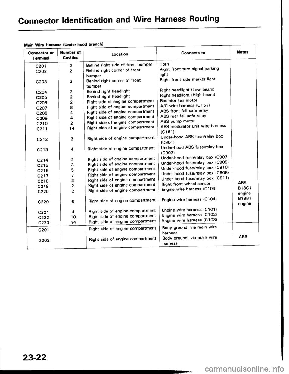
{Undor-hood
Horn
Right tront turn signal/Parking
light
Right Iront side marker light
Right headlight (Low beam)
Right headlight (High beam)
Radiator fan motor
A/C wire harness (C151)
ABS front fail saJe relay
ABS rear fail sate relay
ABS pump motor
ABS modulator unit wire harness
(c161)
Under-hood ABS fuse/relaY box
(c901)
Under-hood ABS fuse/relaY box
(c902)
Under-hood fuse/relay box (C907)
Under-hood tuse/relaY box (C909)
Under-hood fuse/relay box (C9l Ol
Under-hood fuse/relaY box (C908)
Under-hood fuse/relaY box (C91 1)
Right front wheel sensor
Engine wire harness {C 104)
Engine wire harness (C'l 04)
Engine wire harness (C101)
Engine wire harness (C l 02)
Engine wire harness {C 103)
Behind right side of tront bumper
Behind right corner of tront
bumper
Behind right corner of front
bumpet
Behind right headlight
Behind right headlight
Right side of engine comPartment
Right side of engine comPartment
Right side ot engine comPartment
Right side oJ engine comPartment
Right side of engine comPartment
Right side oJ engine comPartment
Right side of engine comPartment
Right side of engine comPartment
Bight side ot engine comPattment
Right side of engine comPartment
Right side of engine comPartment
Right side of engine comPartment
Right side of engine comPartment
Right side of engine comPartment
Right side of engine comPartment
Righl side ot engine comPartmenl
Right side of engine compartmenl
Right side of engine comPartmen'
Right side of engine comPartment
8
4
14
7
J
2
c201
c202
c203
c204
c205
c206
c207
c208
c209
c210
c211
c212
c213
c214
c215
c216
c217
c218
c219
c220
c220
c221
c222
c223
Body ground, via main wire
harness
Body ground, via main wire
harness
Right side of engine compartment
Right side of engine comPartment
23-22