Page 150 of 1413
Crankshaft
Removal
NOTE: End play for th€ connecting rods and crankshaft
should be inspected betore removing the crankshaft.
1. Remove the oil Dan, oil screen and the oil pump.
Remove the baffle plate.
Turn the crankshaft so No.2 and 3 crankpins ar€ at
the bottom.
Remove the right side cover.
OIL PAN
7-10
o@@
5, Remove the bearing cap bolts,
CAUTION: To prevent warPag€, unscrew ths bohr
in 3equoncg 1/3 turn at a tim€; rspeat ihe sgquanco
until all bolts are loos€ned.
Remove the cap bridge {818C1 engine only} and
main caps/bearings. Keep all caps/bearings in order.
Page 151 of 1413

7.
8.
11.
9.
10.
Remove the rod caps/bearings. Keep all caps/bear-
ings in order.
Lift the crankshaft out of the engine, being careful
not to damage journals.
Remove the upper bearing halves from connecting
rods and set them aside with their resDective caDs.
Reinstall main caps and bearings on the engine in
oroDer order.
lf you can feel a ridge of metal or hard carbon
around the top of each cylinder, remove it with a
ndge reamer.
Follow the reamer manufacturer's instructions.
CAUTION: It the ridge is not removed, it may dam-
age the pistons as they are pushed oul.
CRANKSHAFT
RIDGE REAMER
12. Use the wooden handle of a hammer to drive the
prslons ouI.
CAUTION:
a Take care not to damage the contact surfaco ot
the metal gasket.
. When removing the piston/connecting rod, taks
caro not to hit the oil iot {818C1 sngins onlyl.
. It tho oil iet nozzlo is damag6d or bont, replaco
the oil ist assembly (818C1 engine only, page 8-
8).
Reinstall the rod bearings and caps after removing
each piston/connecting rod assembly.
Mark each piston/connecting rod assembly with its
cylinder number to avoid mixup on reassembly.
NOTE: The existing number on the connecting rod
does not indicate its position in the engine, it indi-
cates the rod bore size.
13.
14.
7-11
Page 152 of 1413

EndPlay
NOTE; End play should be inspected before removing
crankshaft.
Push the crank firmly awav from the dial indicator, and
zero the dial against the end of the crank. Then pull the
crank firmly back toward the indicator; dial reading
should not exceed service limit.
Crankshaft End Play:
Standard (New): 0.10 - 0.35 mm
(0.04 - 0.01i| inl
S€rvic€ Limit 0.i15 mm (0.018 inl
. lf end play is excessive, inspect the thrust wash€rs
and thrust surface on the crankshaft. Replace pans as
necessary.
NOTE:
Thrust washer thickness is fixed and must not be
changed either by grinding or shimming.
Thrust washers are installed with grooved sides fac-
ing outward.
Crankshaft
lnspection
. Clean the crankshatt oil passages with pipe cleaners
or a suitable brush.
. Check the keyway and threads.
Alignment
Measure runout on all main journals to make sure the
crank is not bent.
The differ€nce between measurements on each jour-
nal must not be more than the service limit.
Crank3haft Total lndicatod Runout:
Bl8Bl engins:
Sisndod {Nsw): 0.03 mm {0.001 in) max.
Sorvice Limit: 0.05 mm {0.002 inl
818C1 engin€:
Standard {Nsw): 0.020 mm (0.0008 in} mar.
SGrvice Limits: 0.030 mm 10.0012 in)
OIAL INDICATORRotate tlvo completerevolutions.
Support with lathe-
7-12
Page 156 of 1413

Piston
lnstallation
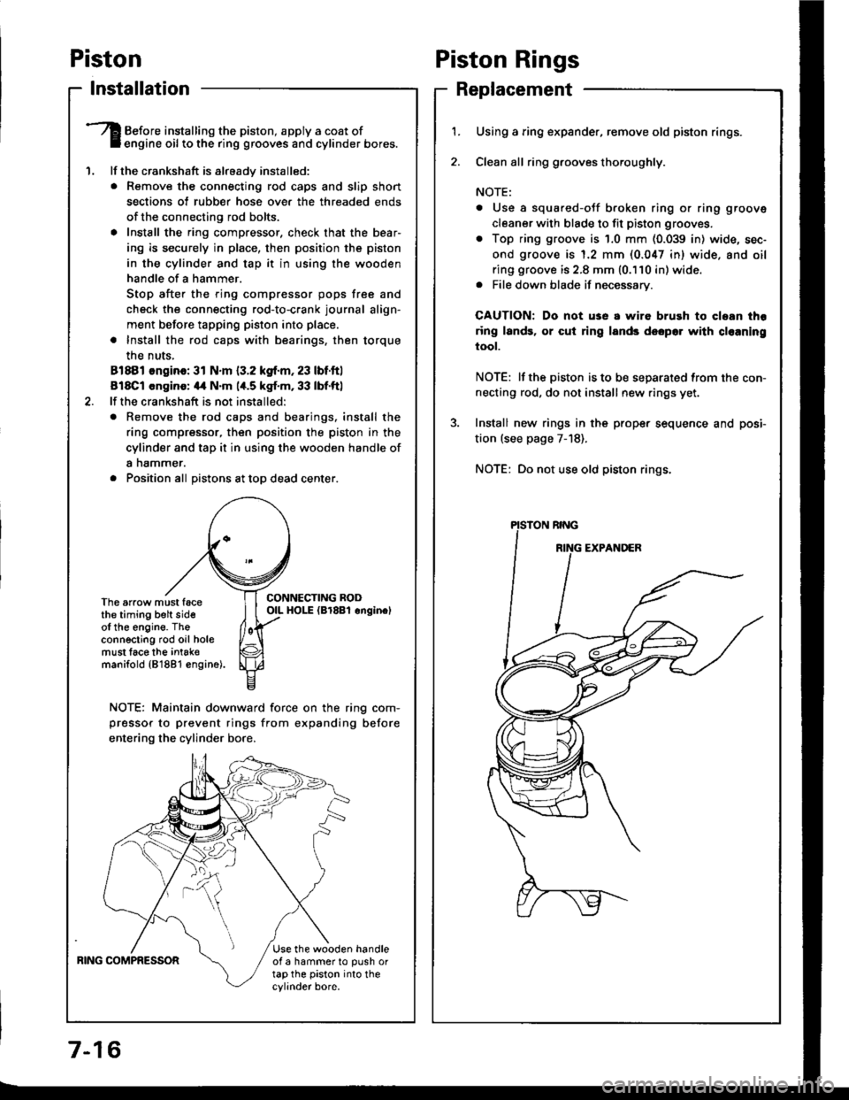
'1.
Before installing the piston, apply a coat ofengine oil to the ring grooves and cylinder bores.
lf the crankshaft is already installed:
. Remove the connecting rod caps and slip short
sections of rubber hose ove. the threaded ends
of the connecting rod bolts.
a Install the ring compressor, check that the bear'
ing is securely in place, then position the piston
in the cylinder and tap it in using the wooden
handle of a hammer.
Stop after the ring compressor pops free and
check the connecting rod-to-crank journal align-
ment before tapping piston into place.
. Install the rod caps with bearings, then torque
the nuts,
81881 ongino: 31 N.m {3.2 kgf.m, 23 lbf.ftl
818C1 cngino: 44 N'm 1,t.5 kgf.m, 33 lbf.ftl
lf the crankshaft is not installed:
o Remove the rod caps and bearings. install the
ring compressor, then position the piston in the
cylinder and tap it in using the wooden handle of
a nammer.
. Position all Distons at toD dead center.
CONNECTING RODOIL HOI-E (Br8Bl onginelThe arrow must facethe timing belt sideof the engine. Theconnecting rod oil holemust lace the intak€manifold {81881 €ngine).
NOTE: Maintain downward force on the ring com-
pressor to prevent rings from expanding before
entering the cylinder bore,
BING COMPRESSORUse the wooden handleof a hammer to push ortap the piston into thecylinder bore.
Piston Rings
Replacement
1.Using a ring expander, remove old piston rings.
Clean all ring g.ooves thoroughly.
NOTE:
. Use a squared-oJf broken ring or ring groove
cleaner with blade to fit piston grooves.
. Top ring groove is 1.0 mm (0.039 in) wide, sec-
ond groove is 1.2 mm (0.047 in) wide. and oil
ring groove is 2.8 mm (0.110 in) wide.. File down blade if necessary.
CAUTION: Do not use a wire brush to cloan thr
ring lands, or cut ring lands dsopo. with cl€aning
tool.
NOTE: lf the piston is to be separated from the con-
necting rod, do not install new rings yet.
Install new rings in the prope. sequence and posi-
tion (see page 7-18).
NOTE: Do not use old piston rings.
Page 161 of 1413
3. Measuro the piston pin-to-piston clearance.
NOTE: Check the Diston for distonion or cracks.
It the piston pin clearance is greater than 0.022 mm(0,0009 in), remeasure using an ovorsize piston pin.
Pbton Pin-to-PLton Cloeranco:
StlndErd (Ncwl: 0.010 - 0.022 mm(0.(xto4 - o.(Xxlg inl
4. Check the difference betwsen piston pin diameter
and connecting rod small end diam€ter.
Pbton Pin-to4onnocting Rod Inlcdaranca:
Strndlrd {Ncw}:
Bl8Bl ongino: 0.013 - 0.G12 mm(0.fiX15 - 0.0013 inl
Bl8Cl cngin.: 0.017 - 0.036 mm
IO.ON1 - O.|,o11 int
Connecting Rods
End Play
NOTE: End play should bs insp€cted before removing
the crankshaft.
Connrcting Rod End Pl.y:
Stlndrrd (Nrwl: 0.15 - o.3o mm(0.(xt6 - 0.012 inl
Scrvict Limit o./to mm (0.016 inl
lf out-of-tolerance, install a new connscting rod.
lf still out-of-to16rance, replace the crankshaft
pages 7-10 and 7-22)
a
a
7-21
Page 162 of 1413

Connecting Rods
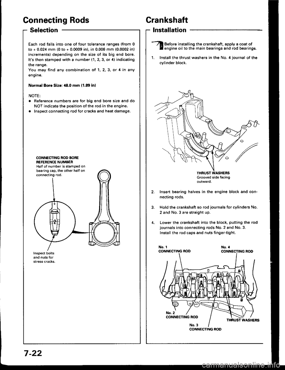
Selection
Each rod falls into one of four tolerance ranges (from 0
to + 0.024 mm (0 to + 0.0009 inl, in 0.006 mm {0.0002 in)
increments) depending on the size ot its big end bore.
It's then stamped with a number (1,2,3, or 4) indicating
the range.
You may find any combination ol 1, 2, 3, or 4 in any
engane.
Normsl Boro Sizoi ,18.0 mm 11.89 inl
NOTE:
a Reference numbers are Jor big end bore size and do
NOT indicate the position of the rod in the engine.
. Inspect connecting rod for cracks and heat damage.
CONNECNNG ROD BOREREFERENCE NUMBERHalf oI number is stamped onbearing cap. th€ other halfonconnecting rod.
Crankshaft
lnstallation
Before installing the crankshaft. apply a coat ofengine oil to the main bearings and rod bearings.
1. Install the thrust washers in the No. 4 iournsl of the
cvlinder block.
Grooved side tacingo!tward
Insert bearing halves in the engine block and con-
necting rods.
Hold the crankshaft so rod journals for cylinders No.
2 and No.3 are straight up.
Lower the crankshaft into the block. putting the rod
journals into connecting rods No.2 and No.3.
Install the rod caps and nuts finger-tight,
CONNECNNG ROD
7 -22
Page 163 of 1413

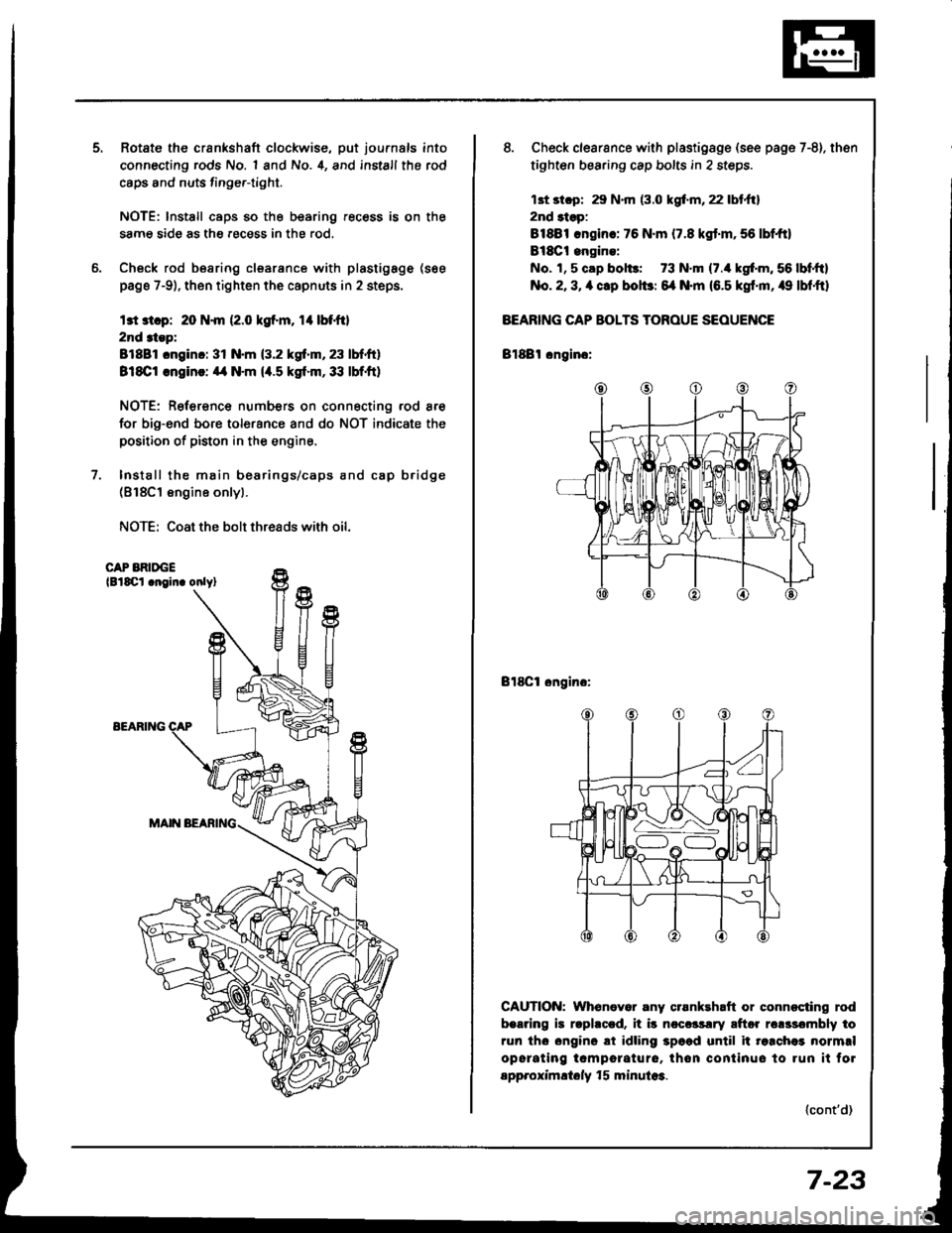
Rotate the crankshaft clockwise, put journals into
connecting rods No. 1 and No. 4, and install the rod
caps and nuts finge.-tight.
NOTE: lnstall caps so the bearing recess is on the
samg side as the .ecess in the rod.
Check rod bearing clsarance with plastigage (see
page 7-9), then tighten the capnuts in 2 steps.
l3t 3t.p: 20 N.m (2.0 kgf.m, rl btfil
2nd 3tep:
81881 cnginc: 31 N.m (3.2 kgf.m, 23 lbf.ft)
818C1 .ngin!: ,14 N.m (4.5 kgt.m,33 lbf.ft)
NOTE: Reference numbers on connecting rod are
for big-end bore tolorance and do NOT indicate the
positioo of piston in the engine.
Install the main bearings/caps and cap b.idge(818C1 engine onlyl.
NOTE: Coat the bolt threads with oil.
CAP BRIDGElBlSCl .noin. onlyl
EEARIlTG
8. Check clearsnce with plastigsge (see page 7-8). then
tighten bearing cap bolts in 2 steps.
13t st.p: 29 N.m (3.0 kgf.m, 22 lbt.ftl
2nd 3tsp:
81881 .ngin.: 76 N.m (7.8 kgt.m,56 lbf,ft)
Bl8Ct engine:
No. 1, 5 cap bol$: 73 N.m (7./r kgf'm, 56 lbf,ftl
No. 2, 3, a clp bolbr 6{ N.m (6.5 kgf'm, /r9 lbf,ftl
BEARING CAP BOLTS TOROUE SEOUENCE
Bl88l cngino:
Bl8Cl ongino:
CAUTION: Whenever any crsnkehaft or connocting rod
b.aring is rlphccd. it i5 ncccrsrry aftor rclssombly to
run tho ongino ai idling 3p6ad until it re.chei normrl
opcrating tcmporature, thon continuo to run it fol
spp.oximltoly f 5 minula3.
(cont'd)
7-23
Page 165 of 1413
11.lnstallthe oil screen.
Installthe oil pan.
NOTE: Clean the oil pan gasket mating surfaces.
Tighten the bolts as shown below.
Torque: 12 N.m {1.2 kgf.m, 9 lbf'ft)
NOTE: Tighten the bolts and nuts in two steps and
toroue the bolts in a crisscross pattern
1'�I
Oil Seal
lnstallation
The seal surface on the block should be dry.
Apply a light cost of oil to the crankshaft and to
the liD of the seal.
Drive in flywheel end seal against right side cover.
NOTE: Drive the end seal in squarely.
DRIVER07t,49 - (xll(xtoo
2. Confirm that clearance is equal all the way around
with a fe€ler gauge.
Cler.6nce: 0.5 - 0.8 mm (0.02 - 0.03 inl
RIGHT SIDECOVER
NOTE: Reter to right column and 8-10 lor installa-
tion of the oil pump side oil seal.
lnstall sealwith thepart number sidetacing out.
7-25