1994 HONDA INTEGRA crankshaft
[x] Cancel search: crankshaftPage 395 of 1413

The Automatic Transmission is a combination of a 3-e,ement torque convefter and triple-shaft electfonically controlled
automatic transmission which provides 4 speeds forward and 1 speed reverse. The entire unit is positioned in line with
the engine.
Torque Converter, Gears and Clutches
The torque converter consists of a pump, turbine and stator assembly in a single unit, The torque converter is connected
to the engine crankshaft so they turn together as a unit as the engine turns. Around the outside of the torque converter
is a ring gear which meshes with the starter pinion when the engine is being staned. The entire torque converter assem-
bly serves as a flywheel while transmitting power to the transmission mainshaft.
The transmission has three parallel shafts, the mainshaft. countershaft and sub-shaft. The mainshatt is in line with the
engine crankshaft.
The mainshaft includes the clutches for 1 st, and 2ndl4th, and gears for 3rd. 2nd, 4th, reverse and l st (3rd gear is in-
tegral with the mainshaft, while reverse gear is integral with the 4th gear).
The countershaft includes the 3rd clutch and gears Ior 3rd, 2nd,4th, reverse, lst and parking. Reverse and 4th gears
can be locked to the countershaft at its center, providing 4th gear or reverse, depending on which way the selector is moved.
The sub-shaft includes the lst-hold clutch and gears for 1st and 4th
The gears on the mainshait are in constant mesh with those on the countershaft and sub-shaft. When certain combina-
tions of gears in the transmission are engaged by the clutches, power is transmitted from the mainshaft to the counter-
shaft via the sub-shatt to provide @, E, tr. tr and @ position.
Electronic Control
The electronic control system consists of the Transmission Control Module {TCM), sensors, and 4 solenoid valves. Shift-
ing and lock-up are electronically controlled for comfortable driving under all conditions.
The TCM is located below the dashboard, behind the left side kick panel on the driver's side.
Hydraulic Control
The valve bodies include the main valve body, secondary valve body, regulator valve body. servo body, and lock-up valve
body throuqh the respective separator plates.
They are bolted on the torque converter housing.
The main valve body contains the manual valve, 1-2 shift valve, 2-3 shift valve, Clutch Pressure Cont.ol (CPC) valve,
4th exhaust valve, relief valve, and oil pump gears.
The secondary valve body contains the 4-3 kick-down valve,3-2 kick-down valve,2-3 orifice cont.ol valve, 3-4 shitt
valve, orifice control valve. modulator valve, and servo control valve
The regulator valve body contains the pressure regulator valve. lock-up control valve, torque converter check valve, and
cooler check valve.
The servo bodv contains the servo valve which is integrated with the reverse shift fork, throttle valve B, and accumulators.
The lock-ug valve bodv contains the lock-up shift valve and lock-up timing B valve. and is bolted on the secondary valve
body.
Fluid from the regulator passes through the manual valve to the various control valves.
Shitt Control Mochanism
Input to the TCM i.om various sensors located throughout the car determines which shift control solenoid valve should
be activated.
Activating a shift control solenoid valve changes modulator pressure, causing a shift valve to move. This pressurizes
a line to one of the clutches. engaging that clutch and its corresponding gear.
Lock-up Mechanism
In @ position. in 2nd, 3rd and 4th, and E position in 3rd, pressurized tluid can be drained from the back of the tor-
que converter through an oil passage, causing the lock-up piston to be held against the torque converter cover. As this
takes Dlace, the mainshaft rotates at the same speed as the engine crankshatt. Together with hydraulic control, the TCM
optimizes the timing ol the lock-up mechanism.
The lock-up valves control the range of lock-up according to lock-up control solenoid valves A and B, and throttle valve B
When lock-up control solenoid valves A and B activate, modulator pressure changes. Lock-up control solenoid valves
A and B are mounted on the torque converter housing, and are controlled by the TCM.
(cont'd)
14-3
Page 431 of 1413

In E position in 2nd, 3rd and 4th, and @ position in 3rd, pressurized fluid is drained from the back of the torque con-
verter through an oil passage, causing the lock-up piston to be held against the torque converter cover. As this takes
place, the mainshaft rotates at the same speed as the engine crankshaft. Together with hydraulic control, the TCM op-
timized the timing ot the lock-up system. Under certain conditions, the lock-up clutch is applied during deceleration, in
3rd and 4th sDeed.
The lock-up system controls the range of lock-up according to lock-up control solenoid valves A and B, and throttle valve B.
When lock-up control solenoid valves A and B activate. modulator pressure changes. Lock-up control solenoid valves
A and B are mounted on the torque converter housing, and are controlled by the TCM.
NOTE:
When used, "left" or " tight" indicates direction on the tlowchart.
LOCK IJP COIITBOL
Solenoid valve
L""f."p "."aiti""\B
Lock-up OFFOFFOFF
Lock-up, slightONOFF
Lock-up, halfONON
Lock-up. fullONON
Lock-up
during decelerationONDuty operation
OFF -ON
LOCI( UP TIMII{G B VAIVE
{cont'd)
ott coot€R
14-39
Page 494 of 1413

Transmission
Removal (cont'dl
'1 9.Remove the right tront mount/bracket, then remove
the end ol the throttle cont.ol cable trom the throt-
tle control lever.
Remove the ATF cooler hoses at the joint pipes. Turn
the ends of the cooler hoses up to prevent ATF from
flowing out, then plug the joint pipes.
NOTE: Check tor any sign ot leakage at the hosejoints.
THROTTLE CONTROL
23. Place a jack under the transmission, raise the lrans-
mission just enough to take weight off ol the
mounts. then remove the transmission mount.
20.
RrcHT FRoNT iiouNT/BRAcKET BoLTsATF COOLERHOSESReplace.24. Remove the t.ansmission housing mounting bolts
and rear engine mounting bolts.
25. Pull the transmission away from the engine until it
clears the 14 mm dowel Dins, then lower it on the
transmission iack.
21. Remove the engine stiftener and totque converter
cover.
22. Remove the eight drive plate bolts one at at time
while rotating the crankshaft pulley.
WASHERSReplace.
'i z/'l e
" (-J t'
14-102
Page 555 of 1413

7.Remove the transmission jack.
Attach the torque converter to the drive plate with
eight bolts and torque:
Rotate the crankshatt as necessary to tighten the
bolts to 1/2 of the specilied torque, then to the final
toaque, rn a cnsscross pattern.
After tighten the last bolts, check that the crankshaft
rotates freely.
TOROUE: 12 N.m {1.2 kgl.m.8.7 lbf.ft}
Install the torque converte. cove. and engine
stiffener.
L
9.
6 r 1.O mm12 N.m 11.2 kgt.m, 8.7 lbl.ltl
10.
12 N.m 11.2 kgf.m,8.7 rbt.ft)
Tighten the crankshaft pulley bolt to specified
rorque.
TOROUE: 177 N.m {18.O kgt.m, 130 lbf'ft}
10 x 1.25 mm44 N'm {4.5 kgf.m.33 rbt'frl
8 x '1.25 mm24 N.m (2.4 kgl.m,17 tbf.trl
lO x '1.25 mm43 N.m14.4 kgf.m, 32 lbf.ltl
11. Connect the ATF cooler hoses to the joint pipes.
12. Connect the throttle control cable to the throttle con-
trol lever and install the right front mount/bracket.
THROTTLE CONTROL LEVERTHROTTLE CONTROLCABLE END
JOINT PIPES
12 x 1 .25 mm64 N.m {6.5 kgf.m,47 tbf.ftlReplace.
ATF COOLER HOSES10 x 1.25 mm RIGHT44 N.m (4.5 kgf'm, FRONT33 rbl.ftl MoUNT/BRACK€T
t5.Install the control lever with a new lock washer to
the control shalt. then install the shift cable cover.
CAUTION: Take care not to bend the shift cable.
CONTROLSHAFT
SHIFT CABLE
CONTROL LEVER
6 x 1.0 mm12 N.m{1.2 kgf.m,8.7 lbl.rr)
SHIFT CABLECOVER
LOCK6 x 1.0 mm14 N.m 11.4 kgl.m,10 lbf.fr)
(cont'dl
Replace.ASHER
14-165
Page 627 of 1413

Inspection and Adjustment
Pump Belt
NOTE: When using a new b€li, first adiust the deflection
or t€naion to the values for the new belt, thsn readiust
ths deflection or tension to the values tor the used b€lt
after running sngine for five minutss.
lnspoction
Attach th€ belt tonsion gauge to th6 belt and measure
ths tension of the bslt.
Tanaion:
U3.d Brft: 391, - 5/O N (lO - 55 kgf, 88 - r20 |bf)
Ncw Bch: 7aO - 89, N (75 - 90 kgt, 170 - 20O lbO
NOTE:
. lf thsre are cracks or any damage evident on the belt,
raplaca it with a now ono.
. Follow the manufacturer's insructions for the tonsion
g8uge.
PUII"EY
07JGG - 00r0r0a
Inspect the pump belt for cracks or any damage.
Replace the belt with a new one if nec€ssary.
Mc!3uramrnl without Bch Tcntion Grugr:
Apply a torce of 98 N (10 kgl, 22 lbll and measure ths
deflection between tho power ste€rin9 pump and tho
crankshaft pulleys.
Daffaction:
U:ed Bch: 11.5- 13.5 mm (0.,t5-0.53 inl
Nlw Brh: 8.0 - 10.0 mm (0.31 - 0.39 inl
here,
17-20
Adiu3tmant
1, Loosen the power stesring pump mounting bolts.
2. Turn ths adiusting bolt to gst the propor bolt ten-
sion, then rstighten the bolts.
3, Start ths €ngine and turn the steering wheel trom
lock-tolock s€veral times, then stop the engino and
recheck ths deflection of the belt.
AD'USN G BOLT
Page 1102 of 1413

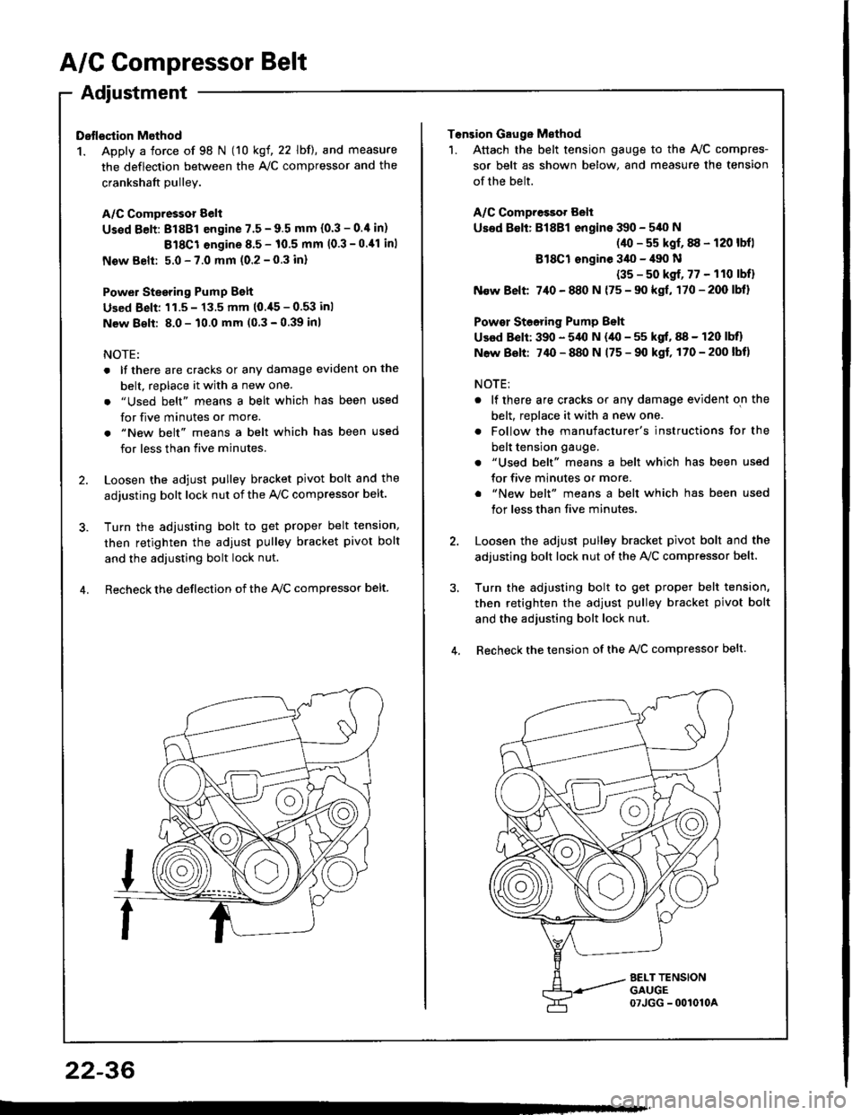
A/C Compressor Belt
Adjustment
Dstlsqtion Method
1. Apply a force of 98 N (10 kgf, 22 lbf), and measure
the deflection between the A,/C compressor and the
crankshaft Dullev.
A/C Compressor Belt
Us€d Eelt: 81881 engine 7.5 - 9.5 mm (0.3 - 0.4 in)
Bl8Cl engine 8.5 - 10.5 mm (0.3 -0.11 inl
New Belt: 5.0 - 7.0 mm (0.2 - 0.3 inl
Power Stesring Pump Belt
Used Beli: 'l1.5 - 13.5 mm (0.,[5 - 0.53 inl
New 8€lt: 8.0 - 10.0 mm (0 3 - 0.39 inl
NOTE:
. lf there are cracks or any damage evident on the
belt, replace it with a new one.
. "Used belt" means a belt which has been used
for five minutes or more.
. "New belt" means a belt which has been used
for less than five minutes.
2. Loosen the adjust pulley bracket pivot bolt and the
adjusting bolt lock nut of the Ay'C compressor belt.
3. Turn the adiusting bolt to get proper belt tension,
then retighten the adjust pulley bracket pivot bolt
and the adjusting bolt lock nut.
4. Recheck the deflection of the lvc compressor belt
22-36
Tonsion Gauge Method
1. Attach the belt tension gauge to the Ay'C compres-
sor belt as shown below, and measure the tension
of the belt.
A/C Compressot Belt
Used 8€lt: Bl8Bl engine 390 - 540 N
(40 - s5 kgf, 88 - 120 lbfl
Bl8Cl ongine 3il0 - il90 N
(35 - s0 kgf, 77 - 110 lbfl
N€w Belt 7,10 - 880 N {75 - 90 kgf, 170-200lbl}
Powor Steoring Pump Belt
Used Belt: 390 - 5,{l N (40 - 55 kgf, 88 - 120 lbll
N6w Bolt: 74O - 880 N 175 - 90 kgf, 170-200lbt)
NOTE:
. lf there are cracks or any damage evident on the
belt, replace it with a new one.
. Follow the manufacturer's instructions for the
belt tension gauge.
. "Used belt" means a belt which has been used
for five minutes or more.
. "New belt" means a belt which has been used
tor less than five minutes,
2. Loosen the adjust pulley bracket pivot bolt and the
adjusting bolt lock nut of the AVC compressor belt.
3, Turn the adjusting bolt to get proper belt tension,
then retighten the adjust pulley bracket pivot bolt
and the adjusting bolt lock nut.
4. Recheck the tension of the A{/C compressor belt.
Page 1122 of 1413

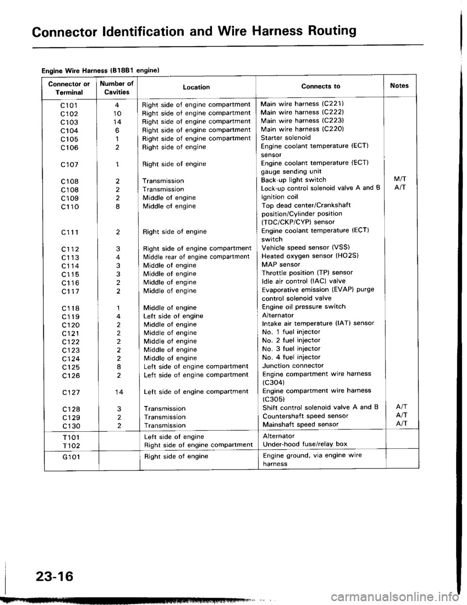
Gonnector ldentification and Wire Harness Routing
Engine Wire Harness {B1881engine)
Connector 01
Terminal
Number of
CavitiesLocationConnects ioNotes
c10'l
c102
c103
c104
c 105
c106
c107
c108
c108
c109
c110
c111
c113
c114
c115
Lt to
c117
c118
c119
c't 20
c121
c122
c123
cl24
c125
c't26
c127
c128
c129
c130
10
14
6
1
1
2
2
8
2
3
t
1
2
2)
2
8
14
2
2
Right side of engine compartment
Right side of engine compartment
Right side of engine compartment
Right side ol engine compartment
Right side of engine compartment
Right side of engine
Right side ol engine
Transmission
Transmission
Middle of engine
lvliddle of engine
Right side ot engine
Right side of engine compartment
ldiddle rear of engine compartment
Middle of engine
Middle ol engine
Middle of engine
Middle of engine
Middle ot engine
Left side of engine
lvliddle of engine
Middle of engine
Middle of engine
Middle ot engine
Middle ol engine
Left side of engine compartment
Left side of engine compartment
Left side of engine compartment
Transmission
Transmission
Transmission
Main wire harness (C221)
Main wire harness {C222}
Main wire harness (C223)
Main wire harness {C220)
Starter solenoid
Engine coolant temperature {ECT)
sensor
Engine coolant temperature (ECT)
gauge sending unit
Back'up light switch
Lock-up control solenoid valve A and B
lgnition coil
Top dead center/Crankshaft
position/Cylinder position
(TDC/CKP/CYP) sensor
Engine coolant temperature (ECT)
switch
Vehicle speed sensor (VSS)
Heated oxygen sensor (HO2S)
MAP sensor
Throttle position (TP) sensor
ldle air control (lAC) valve
Evaporative emission (EVAPI purge
control solenoid valve
Engine oil pressure switch
Alternator
Intake air temperature {lAT} sensor
No. 'l fuel injector
No. 2 tuel injector
No. 3 fuel injector
No. 4 fuel injector
Junction connector
Engine compartment wire harness
(c304)
Engine compartmenl wire harness
(c305)
Shift control solenoid valve A and B
Countershait speed sensor
Mainshaft speed sensor
M/T
NT
NT
NT
T 101
r102
Lelt side oI engine
Right side of engine compartment
Alternator
Under-hood tuse/relay box
G 101Right side of engineEngine ground, via engine wire
harness
23-16
Page 1124 of 1413

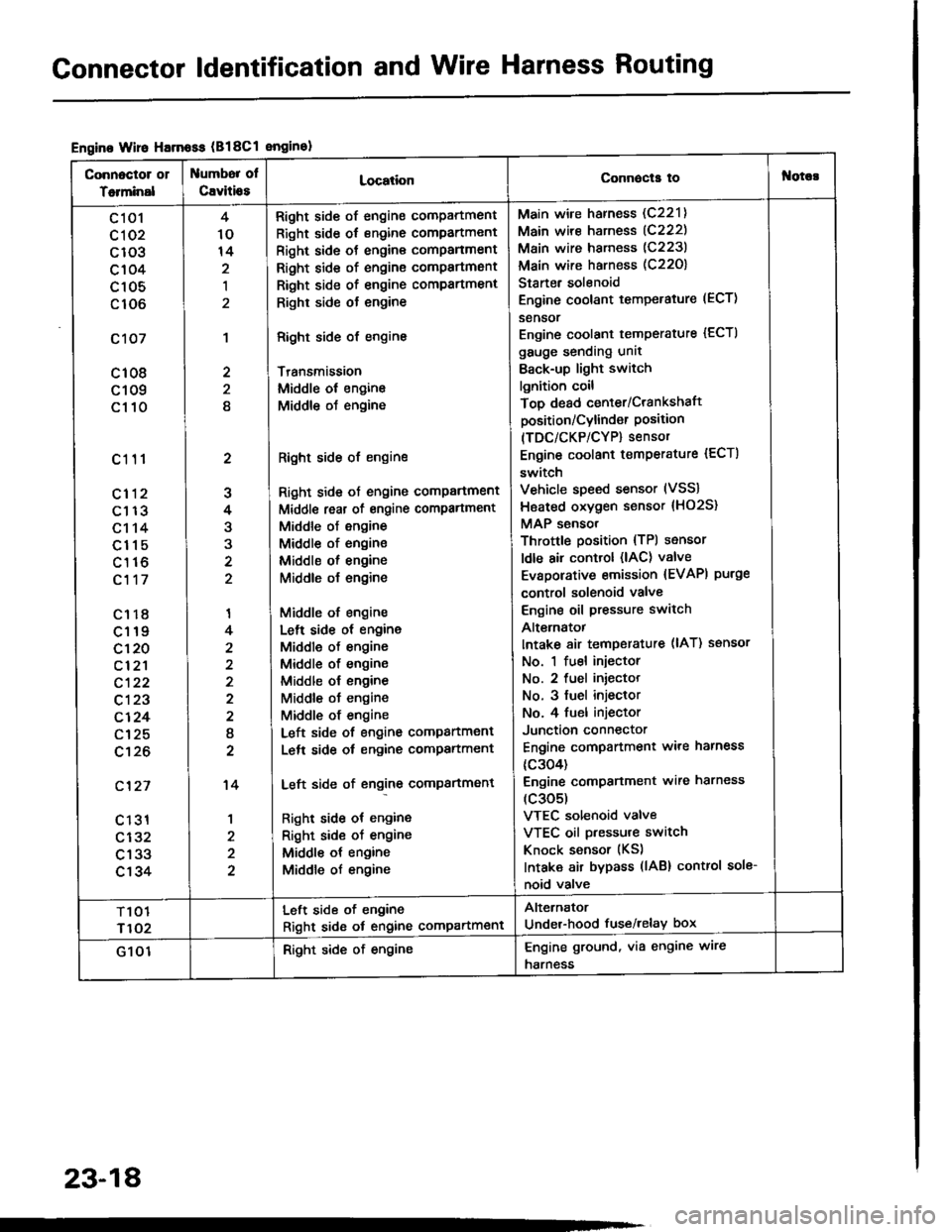
Gonnector ldentification and Wire Harness Routing
Engine Wire Harnoss (B18Cl enginol
Connoctor 01
Totminal
umbor ol
Cavitio8LocationConnecla tof{orc!
c 101
cl 02
c103
c104
c105
c106
c107
c108
c109
c110
c111
cl12
c113
c114
c115
c116
c117
c1r8
c119
c120
cl2'l
c122
c123
c124
c125
c't26
c'127
c 131
c132
c133
c134
2
J
4
3
'I
4
2
I
2
't4
1
4
10
14
,l
2
2
8
Right side of engine compartment
Right side of engine compartment
Right side ot engine comPanment
Right side of engine compartmsnt
Right side of engine compartment
Righr side ot engine
Right side of engine
Transmission
Middle ol engine
Middle oJ engine
Right side of engine
Right side ot engine comPartment
Middl€ reat of engine compartment
Middle of engine
Middle of engine
Middle ol engine
Middle o{ engine
Middle of engine
Lelt side ot engine
Middle of engine
Middle of engine
Middle ol engine
Middle ot engine
Middle of engine
Left side of engine companment
Lelt side ot engine compartment
Left side of engine compartment
Right side ot engine
Right sid€ of engine
Middle ot engine
Middle of engine
Main wire harness (C221)
Main wire harness (C222)
Main wire harness (C223)
Main wire harness (C22O)
Starter solenoid
Engine coolant temperature (ECT)
sensor
Engine coolant temperature {ECTI
gauge sending unit
Back-up light switch
lgnition coil
Top dead center/Crankshaft
position/Cylind€r Position(TDC/CKP/CYP) sensor
Engine coolant temperature {ECT)
switch
Vehicle speed sensor (VSS)
Hsated oxygen sensor {HO2S}
MAP sensor
Throttle position {TPl sensor
ldle air control (lAC) valve
Evaporative emission {EVAPI purge
control solenoid valve
Engine oil pressure switch
Alt€rnatot
Intake 8ir temperature (lAT) ssnsor
No. 1 fuel injector
No. 2 fuel iniector
No. 3 fuel injeclor
No. 4 fuel injector
Junction connector
Engine compartment ware harness
{c304)
Engine comPanment wire harness
(c305)
VTEC solenoid valve
VTEC oil pressure switch
Knock sensor (KS)
Intaka air bypass (lAB) control sole-
noid valve
T101
r102
Left side of engine
Right sid6 ot engine compartment
Alternator
Under-hood fuse/relay box
G 101Right side of engineEngine ground, via engine wire
harness
23-18