Page 1231 of 1413

Low FuelIndicator
IndicatorLight Test
Seat Belt Reminder
System
Seat Belt Switch Test
J.
NOTE: Reter to page 23- 1 1 6 tor the wiring description
of the low fuel indicator circuit.
1. Park car on level ground.
@ oo not rmoko whil6 working on th€
fuol system, Keop op€n llamg3 awsy from your work
area. Drain fuel only into an approvod container,
Drain tuel into an 8pplov€d container. Then install
the drain bolt with a new washer.
Add less than 8.2 t (2.2 U.S.Gal, 1.8 lmp.Gal) of fuel
and turn the ignition switch ON (ll). The low fuel in-
dicator light should com€ on within lour minutes,
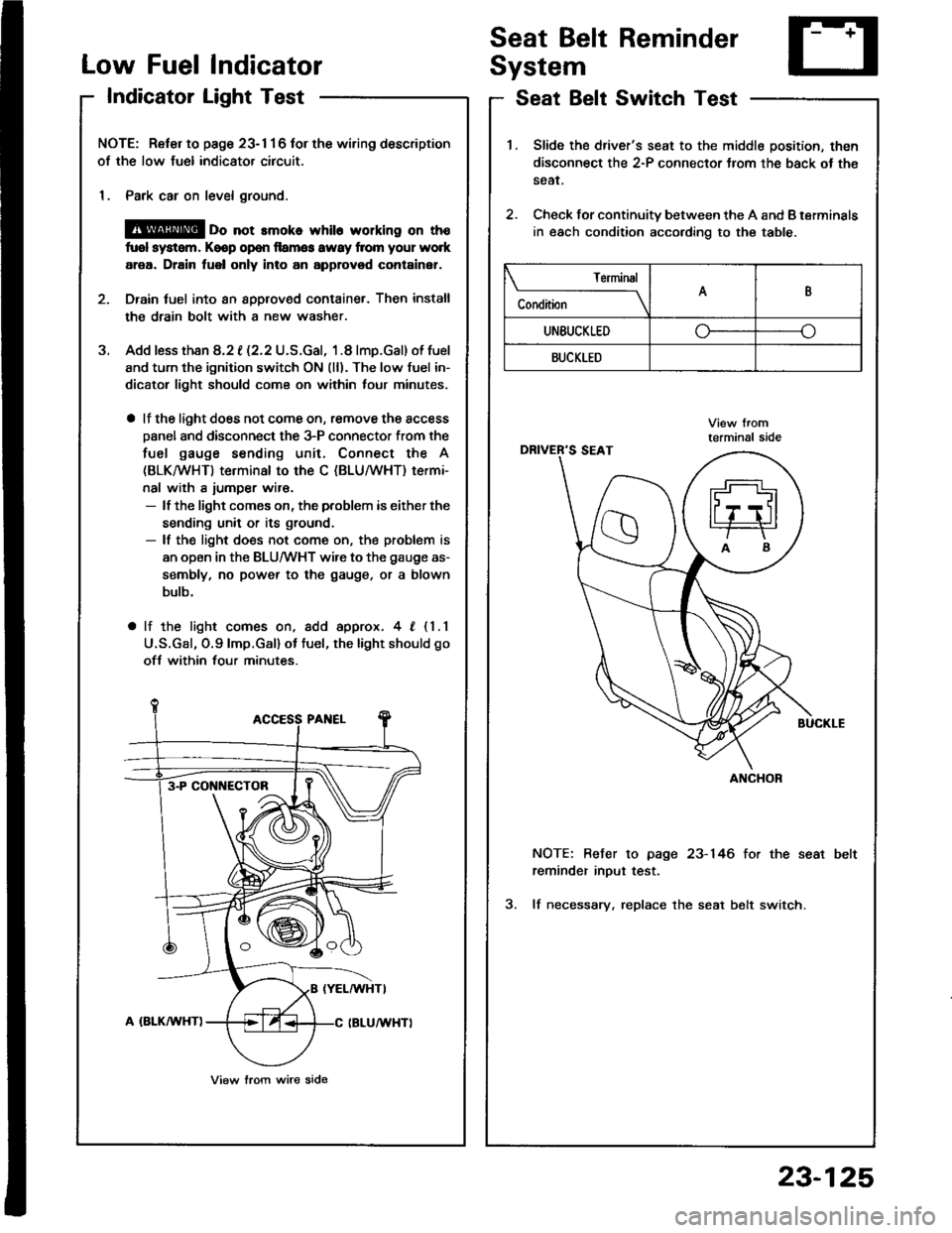
a lf the light does not come on, remove the access
Danel and disconnect the 3-P connector from the
fuel gauge sending unit, Connect the A
(BLKMHT) terminal to the C (BLU/WHT) termi-
nal with a iumper wir€.- lf the light comes on, the problem is either the
sending unit or its ground.- lf the light does not come on, the problem is
an open in the BLU/WHT wire to the gauge as-
sembly, no power to the gauge, or a blown
bulb.
a lf the light comes on, add approx. 4, {1.1
U.S.Gal, O.9lmp.Gal) ot tuel, the light should go
ofJ within four minutes.
3-P CONI{ECTOB
View lrom wire side
1.Slide the driver's seat to the middle position, then
disconnect the 2-P connector Jrom the back ot th€
sear.
Check for continuity between the A and B terminals
in each condition according to the table.
2.
NOTE: Befer to page 23-146 for the seat
reminder inout test.
3. lf necessary. replace the seat belt switch.
Terminal
C"** \AB
UNEUCKLEDo--o
BUCKLED
ANCHOR
23-125
Page 1312 of 1413
Rear Window Defogger
Component Location Index
CAUTION:
a All SRS olectrical wi ng ham€$6s are covoled with
y€llow insulation.
B6foro disconnocting any part of ths SRS wire har-
ness. connoct tho short connector(s).
Roplacs the ontire affectod SRS harness assombly if
it has an open circuit or damagcd wiring.
REAB WINDOWDEFOGGER RELAYTest, page 23-68
REAR WINDOWDEFOGGER SWITCHRemoval, page 23-209Test, page 23-2Og
REAR WINDOW DEFOGGERTest, page 23-210
UI{DER.DASH FUSE/RELAY BOX
REAR WINDOW DEFOGGER TIMER CIRCUIT
{ln the integrated control unil)fnput Test, page 23-147
SRS MAII{ HAR'{ESS
The rear window defogger is controlled by the integrated control unit, Pushing the defogger switch in the instrument
panel it sends a signal to the defogger time. in the integrated control unit, and the detogger stays on tor 25 minutes
or until the ignition switch is turned off. The indicator light in the switch comes on when the deJogger works.
23-206
Page 1314 of 1413
Rear Window Defogger
Troubleshooting
NOTE: The numbers in the table show the troubleshooting sequence.
'1: Hatchback'2: Sedan
Item to be inspected
Symptom
o
'
lD
*o--
o!
zi
ii9c
.E
o.-
:E
go
.E6
5.
o0to9\cg
o5('r6
z)
;5
o
!
ooooo
=3
oEDo
o
o
oo-
@=
g8
oo
o5
Defogger works, but indicator
light does not go on.1BLKTYEL oT BLU/YEL
Defogger does not work and
indicator light does not go on.122G201
G401YEL, BLUfYEL or BLK/YEL
Defogger does not work, but
indicstor light goes on.1423'1i G771',: G5O3
BLU|YEL or BLKIYEL
BLK/GRN oT BLKMHT
Defogger-on time is too long or
too short (normal operation time
is 25 minutes).
1
23-208
IINIilfi
Page 1316 of 1413

Rear Window Defogger
Function Test
CAUTION: Be carelul not to scratch 01 damago ths
defogger wires with th€ tsster probe.
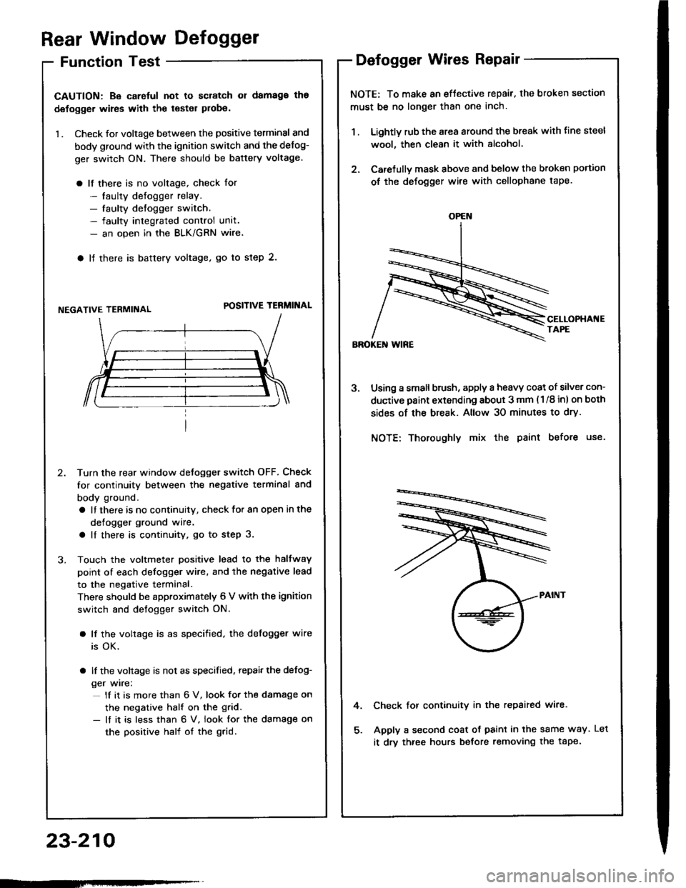
1 . Check for voltage between the positive terminal and
body ground with the ignition switch and the delog-
ger switch ON. There should be battery voltage.
a lf there is no voltage, check for
- laulty detogger relay.- faulty defogger switch.- faulty integrated control unit.- an open in the BLK/GRN wire
a lJ there is baftery voltage, go to step 2.
NEGATIVE TERMIiIALPOSITIVE TERMINAL
Turn the rear window detogger switch OFF, Check
for continuity between the negative terminal and
body ground.
a It there is no continuity, check to. an open in the
defogger ground wire.
a ll there is continuity, go to step 3.
Touch the voltmeter positive lead to the halfway
point of each defogger wire, and the negative lead
to the negative terminal.
There should be apptoximately 6 V with the ignition
switch and defogger switch ON.
a lf the voltage is as specified, the defogger wire
is OK.
a lf the voltage is not as specified. repai, the defog-
ger wire:
lf it is more than 6 V, look for the damage on
the negative half on the grid.
- lf it is less than 6 V. iook for the damage on
the positive half of the grid.
Defogger Wires Repair
NOTE: To make an eftective repair. the broken section
must be no longer than one inch.
1 . Lightly rub the area around the break with line steel
wool, then clean it with alcohol.
2. Carefullv mask above and below the broken portion
of the defogger wire with cellophane tape.
Using a small brush, apply a heavy coat of silver con-
ductive paint extending about 3 mm ( 1/8 inl on both
sides of the break. Allow 30 minutes to dry.
NOTE: Thoroughly mix the paint before use.
Check for continuity in the repaired wire.
Apply a second coat of paint in the same way.
it drv three hours betore removing the tape.
4.
OPEN
23-210
tLet
Page 1405 of 1413

Supplemental Restraint System (SRSI
Airbag Assembly Disposal (cont'd)
Connect a l2 volt batterv to the tool:
. lf the green light on the tool comes on, th€
airbag igniter circuit is d€fective and cannot
deploy the airbag. Go to Dsmag€d Airbag
Special Procedure.
. lf the red light on the tool comes on, the airbag is
ready to be deployed.
Push the tool's deployment switch. Th6 sirbag
should deploy (deployment is both highly audible
and visibls - a loud noise and raDid inflation of the
bag, followed by slow deflationl.
. lf audible/visible deploym€nt happsns and the
green light on the tool comes on, continus with
this Drocedure.
. lf the airbag doesn't deploy, yet the green light
comes ON, its igniter is dofectiv€. Go to
Damaged Airbag Special Procedure.
@ During deploym€nt, the airbsg assom-
bly can become hot enough to burn you. Wait thirty
minutes after deployment beforo touching the
assemblv.
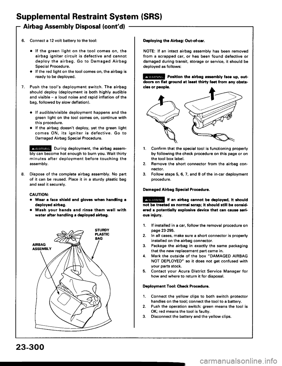
Dispose of the complete airbag sssembly. No pan
of it can be reused. Place it in I sturdy plastic bag
and seal it securelv.
CAUTION:
Woar a taco shiold lnd glov.s whon hlndling !
doploy.d airbag.
Waeh your hands and rin3a tham wall with
wslor aftor handling r deploycd !irb!g.
23-300
Doploying the Airbag: Out-ot{!r.
NOTE: lf an intsct airbag assembly has been removed
from a scrapped car, or has been found dofective or
damagsd during transit, storage or service, it should bs
dsployed as follows:
@ Porition th6 lirbrg rr:.mbly t.ce up, out-
doo6 on flat ground !t lorrt thirty foot from rny ob3t..
clar or pcoplo.
1. Confirm that the special tool is functioning properly
by following the check procedure on this page or on
the tool box label.
2. Remove the short connector from the airbag con-
nector.
3. Folfow steps 5,6,7, and 8 of the in-car deployment
orocequre.
Dlmlged Airbsg Sp.ci8l Procoduro.
E!@ f rn lirbag crnnot be deploy.d, it rhould
not br trcltcd !s normll scrrp; ii 3hould still bc comid-
ercd a potantillly oxplolivr dcvicc thli cln c!u3a 3ari-
ou3 iniury.
1. lf instslled in a car, follow the removal procedure on
page 23-295.
2. In all cases, make sure a short connector is properly
installed on the airbag conn€ctor.
3. Package the airbag in sxacily the same packaging
that the now replacement part cama in.i[. Mark the outside 0f the box "DAMAGED AIRBAG
NOT OEPLOYED" so it does not get confused with
your parts stock.
5. Contact your Acura District Service Manager for
how and where to return it for disoosal.
Dcploymont Tool: Chcck Procedure.
1. Connect the yellow clips to both switch protector
handles on the tool; connect the tool to a battery.
2. Push th€ operation switch: green means the tool is
OK; red means the tool is faulty.
3. Disconnect the battery and the yellow clips.