1994 HONDA INTEGRA Minutes
[x] Cancel search: MinutesPage 944 of 1413

9. With a sponge. apply a light coat of glass primer tothe inside face ot the quarter glass, as shown, thenlightly wipe it ott with gauze or cheesecloth.
NOTE:
a Do not apply body primer to the quaner glass, anddo not get body and glass primer sponges mixedup.
a Never touch the primed surlaces with your hands.lf you do, the adhesive may not bond to the quan-
er glass properly, causing a leak after the quarterglass is installed.
a Keep water, dust. and abrasive materials awavfrom the primed surface.
V/// , AooV glass primer h6re-
10 mm lO.4 inl
10 mm lO,4 inl
1O. Install the quarter trim.
1 1. With a sponge. apply a light coat of body primer tothe original adhesive remaining around the quarte.glass opening flange.
Let the body primer dry lor at least 1O minutes.
NOTE:
a Do not apply glass primer to the body, and becareful no1 to mix up glass and body prime.
sponges.
a Never touch the primed surfaces with your hands.
'////7, , aepty body p.imer here.
lO.2 inl5mm
ffi
16 mm{0.63 in}
'16 mm(0.63 inl
6mm10.24 in)
OUARTERTRIM
(cont'd )
OUARTER
5 mrr| 10.2 inl
20-75
Page 945 of 1413

Ouarter Glass
SIOE SPACER
ADHESIVETAPE A
Replacement (cont'd)
1 2. Thoroughly mix the adhesive and hardener together
on a glass or metal plate with a putty knife.
NOTE:
a Clean the plate with a sponge and alcohol before
mixing.
a Follow the instructions that came with the
adhesive.
13. Before tilling a cartridge, cut the end of the nozzle,
as shown.
Cut nozzle end,as shown.10 mm 10.39 in)
7 mm {0.27 inl
14. Pack adhesive into the cartridge without air pock-
ets to ensure continuous delivery. Put the cartrige
in a caulking gun, and run a bead of adhesive around
the edge of the quarter glass as shown.
NOTE:
a After applying the adhesive, peel the separator
off the double-faced adhesive tapes.
a Apply the adhesive within 30 minutes after ap-
plying the glass Primer.
t1;T,,1 :ADt'�Es'�vE
I mm 10.3 in)
8 mm lO.3 in)
IJ,
L_-_2mm {0.08-1r
*-{6
AOHESIVE TAPES 8
20-76
'12 mm (0.47 inl2 mm lO.O8 in)
--
t5.Install the fasteners to the body as shown.
Use suction cups to hold the quarter glass over the
opening, align it with the clip setting points, and set
it down on the adhesive. Lightly puch on the quart-
er glass until its edges are tully seated on the adhe-
sive all the way around.
NOTE: Do not open or close the doors until the
adhesive is dry.
to.
17. Scrape or wipe the excess adhesive off with a put-
ty knile or towel,
NOTE: Use a soft shop towel dampened with alco-
hol to remove adhesive from a painted surface or the
quarler glass.
18. Let the adhesive dry for at least one hour, then spray
water over the quarter glass and check for leaks'
Mark leaking areas and let the quarter glass dry, then
seal with sealant.
NOTE: Let the car stand for at least tour hours at-
ter quarter glass installation. lf the car has to be used
within the f irst four hours, it must be driven slowly.
'19. Reinstall all remaning removed parts.
Page 1092 of 1413
A/G System Service
Performance Test
The performance test will help determine if the air con-
ditioner system is operating within specitications.
Only use service equipment that is U.L.-listed and is cer-
tified to meet the requirements of SAE J2210 to remove
HFC-134a {R-134a) from the air conditioner system.
CAUTION: Exposure to air conditioner relrig€rant and
lubricant vapor ot mist can irritate eyes, nose and
throat. Avoid breathing the air conditioner rstrigerant
and lubricant vapor or mi3t.
It accidental system discharge occurs, ventilate work
area before resuming service.
R-134a service equipment or vehicle air conditioner sys-
tems should not be pressure tested or leak tested with
comPressed atr.
!@ some mixtures ot air and R'1344 hrv6
been shown to be combustibls at elovatod prsssurel
and can result in firg or explosion causing iniury 01
property damage. Ngvor usg compregsed ail to prossuro
t€st R-134a ssrvice equipment or vohicl€ air conditioner
syst€ms.
Additional health and safety information may be
obtained from the refrigerant and lubricant manufactur-
ers.
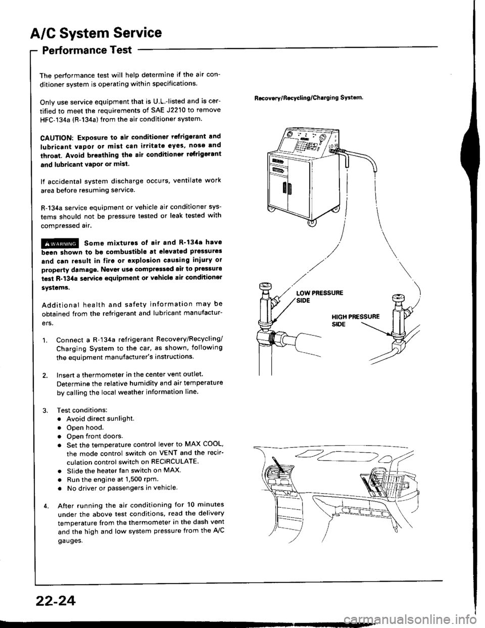
1. Connect a R-134a refrigerant Recovery/Recycling/
Charging System to the car, as shown, iollowing
the equipment manufacturer's instructions.
2. Insert a thermometer in the center vent outlet.
Determine the relative humidity and air temperature
by calling the local weather information line,
3. Test conditions:
. Avoid direct sunlight.
. Open hood.
. Open front doors
. Set the temperature control lever to MAX COOL,
the mode control switch on VENT and the recir-
culation control switch on RECIRCULATE.
. Slide the heater fan switch on MAX
. Run the engine at 1,500 rPm
. No driver or passengers in vehicle.
4. After running the air conditioning for 10 minutes
under the above test conditions. read the delivery
temperature from the thermometer in the dash vent
and the high and low system pressure from the A,/C
gauges.
Rocov.rylB.cycling/Ch!lging SFtrm.
PRESSURELOW
22-24
Page 1102 of 1413
A/C Compressor Belt
Adjustment
Dstlsqtion Method
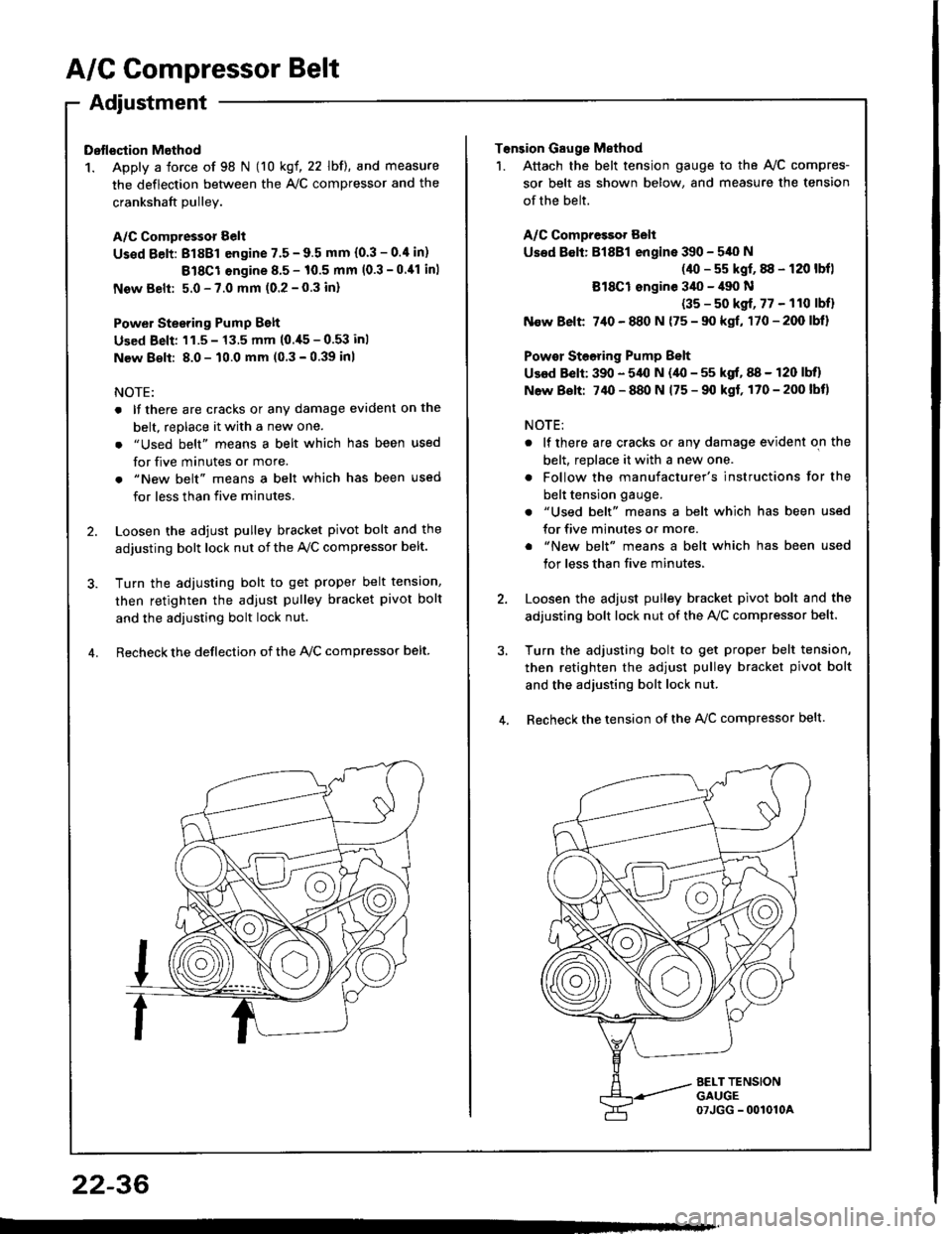
1. Apply a force of 98 N (10 kgf, 22 lbf), and measure
the deflection between the A,/C compressor and the
crankshaft Dullev.
A/C Compressor Belt
Us€d Eelt: 81881 engine 7.5 - 9.5 mm (0.3 - 0.4 in)
Bl8Cl engine 8.5 - 10.5 mm (0.3 -0.11 inl
New Belt: 5.0 - 7.0 mm (0.2 - 0.3 inl
Power Stesring Pump Belt
Used Beli: 'l1.5 - 13.5 mm (0.,[5 - 0.53 inl
New 8€lt: 8.0 - 10.0 mm (0 3 - 0.39 inl
NOTE:
. lf there are cracks or any damage evident on the
belt, replace it with a new one.
. "Used belt" means a belt which has been used
for five minutes or more.
. "New belt" means a belt which has been used
for less than five minutes.
2. Loosen the adjust pulley bracket pivot bolt and the
adjusting bolt lock nut of the Ay'C compressor belt.
3. Turn the adiusting bolt to get proper belt tension,
then retighten the adjust pulley bracket pivot bolt
and the adjusting bolt lock nut.
4. Recheck the deflection of the lvc compressor belt
22-36
Tonsion Gauge Method
1. Attach the belt tension gauge to the Ay'C compres-
sor belt as shown below, and measure the tension
of the belt.
A/C Compressot Belt
Used 8€lt: Bl8Bl engine 390 - 540 N
(40 - s5 kgf, 88 - 120 lbfl
Bl8Cl ongine 3il0 - il90 N
(35 - s0 kgf, 77 - 110 lbfl
N€w Belt 7,10 - 880 N {75 - 90 kgf, 170-200lbl}
Powor Steoring Pump Belt
Used Belt: 390 - 5,{l N (40 - 55 kgf, 88 - 120 lbll
N6w Bolt: 74O - 880 N 175 - 90 kgf, 170-200lbt)
NOTE:
. lf there are cracks or any damage evident on the
belt, replace it with a new one.
. Follow the manufacturer's instructions for the
belt tension gauge.
. "Used belt" means a belt which has been used
for five minutes or more.
. "New belt" means a belt which has been used
tor less than five minutes,
2. Loosen the adjust pulley bracket pivot bolt and the
adjusting bolt lock nut of the AVC compressor belt.
3, Turn the adjusting bolt to get proper belt tension,
then retighten the adjust pulley bracket pivot bolt
and the adjusting bolt lock nut.
4. Recheck the tension of the A{/C compressor belt.
Page 1104 of 1413
A/G System Service
Evacuation
Only use service equipment that is U.L.-listed and is cer-
tified to meet the roquirements of SAE J2210 to remove
HFC-134a (R-134a) lrom the 8ir conditioner system.
CAUTION: Exposulo to 6ir conditioner refligorrnt and
lubricani vapor or mi3t crn i.ritato 9y33, noaa and
thrort. Avoid bratthing ths .ir conditionor rsfrigorrnt
snd lubricsnt vtpor or mist.
lf accidental system discharge occurs, ventilate work
area before resuming service.
R-134a service equipment or vehicle 8ir conditioner sys-
tems should not be pressure tested or leak tested with
compressed ait.
!@ somo mixtuto3 ot ril and R'134! hav.
been shown to bo combustible at olevltad prossulo3
and can re3ult in fire or explosion crusing inlurY or
property damago, Navor us! comprossod air to prgsauro
test R-13/aa 3orvicr €quipmlnl or vohiclo air conditionol
sy3lems.
Additional health and safety information may be ob-
tained from the retrigerant and lubricant manufactures.
1. When an Ay'C System has been opened to the atmo-
sDhere, such as during installation or repair, it must
be evacuated using a R-134a refrigerant Recovery/
Recycling/Charging System. {lf the system has been
open for several days, the receiver/dryer should be
replaced.l
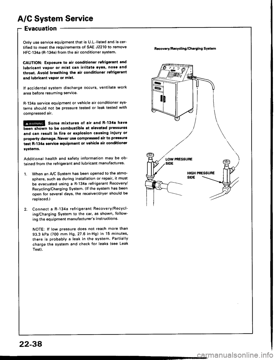
2. Connect a R-134a refrigerant Recovery/Recycl-
ing/Charging System to the car, as shown, follow-
ing the equipment manufacturer's instructions.
NOTE; lf tow pressure does not reach more than
93.3 kPa (700 mm Hg, 27.6 in'Hg) in 15 minutes,
there is probably a leak in the system. Partially
charge the system and check tor leaks {see Leak
Test).
R.cov.ry/R.cycling/Chtroing Syttom
PRESSUREaotnSIDE
2234
Page 1172 of 1413

Battery
a Battory tluid (6lectrolyt€l contains sulturic acid. lt may cauaa aevere burns iI it gots on your skin or in youl oyos.
Woar protoctivo clothing and I fac€ shield,- ll aloctrolyt6 gots on youl skin or clothos, rimo it off with wator immediately,- lf eloclrolyto g6ts in your oyos, tlush it out by splashing wat6r in youl eyes for at least 15 minutes; call a physiclan
immediately,
a A battery gives off hydrogon gas, lf ignit6d. tha hydrogsn will orploda and could crack tho baflory cas6 and splattor
acid on you. Koep spa*s. flames, and cigarottos away from the baftery.
a Overcharging will raiso ths tempelature ot th€ electrolyte. This may force electrolyte to splay out of the battery venta.
Follow lhe chargor manutacturer's instluctions and chargo tho battory at a prop61 rate.
NOTE: The original radio has a coded theft protection circuit. lt service to the car requires any of the lollowing, be sure
to get the customer's code number before- disconnecting the battery.- removing No. 32 (7.5 Al fuse from the under-hood fuse/relay box- removing the radio,
After service, reconnect power to the radio and turn it on. When the word "CODE" is displayed, enter the customer's
s-digir code to restore radio operation,
Use either a JCI or Bear ARBST tester, and follow the manufacturer's procedures. It you don'r have one of these com-puterized testers, follow this conventional test procedure:
To get accurate results, the temperature ot the electrolyte must be between TOoF l21ool and IOOoF {38oCl.
lf the case is cracked or the posts are loose,
replace the battery.
lf the indicator shows low electrolvte, add
distilled water it oossible.
Test Load Cspacity (# 1)
. Apply 3OO amp losd fo. 15 seconds to remove
surJace charge.. Allow 15 seconds recovery period.. Apply test load (see Test Load Chartl.. Record voltage at the end of 15 seconds.
Voltage stays above 9.6
volts: The batterv is OK.
23-66
Page 1173 of 1413
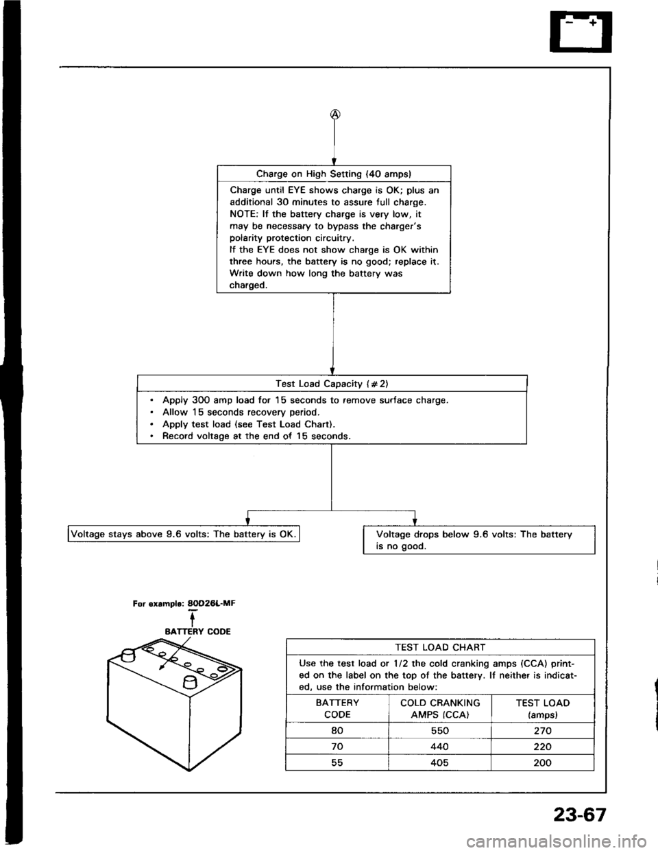
Charge on High Setting {4O ampsl
Charge until EYE shows charge is OK; plus an
additional 30 minutes to assure tull charge.
NOTE: lf the battery charge is very low, it
may be necessary to bypass the charger'spolarity protection circuitry.
lf the EYE does not show charge is OK within
three hours, the battery is no good; replace it.
Write down how long the battery was
charged.
Test Load Capacity l#21
Apply 300 amp load for 15 seconds to remove surface charge.
Allow 15 seconds recoverv Deriod.
Apply test load (see Test Load Chan).
Record voltaoe at the end of 15 seconds.
Voltage stays abov€ 9.6 volts: The Uattery is Of. IVoltage drops below 9.6 volts: The battery
is no good.
AOD26L.MF.-IIERY COOE
For oramplo:
BATTERY COOE
TEST LOAD CHART
Use the test load ot 112 the cold cranking amps (CCA) print-
ed on the label on the top of the battery. lf neithe. is indicat-
ed, us€ the information below:
BATTERY
CODE
COLD CRANKING
AMPS (CCA)TEST LOAD
lamps,
80550270
70440220
55405200
23-67
Page 1214 of 1413
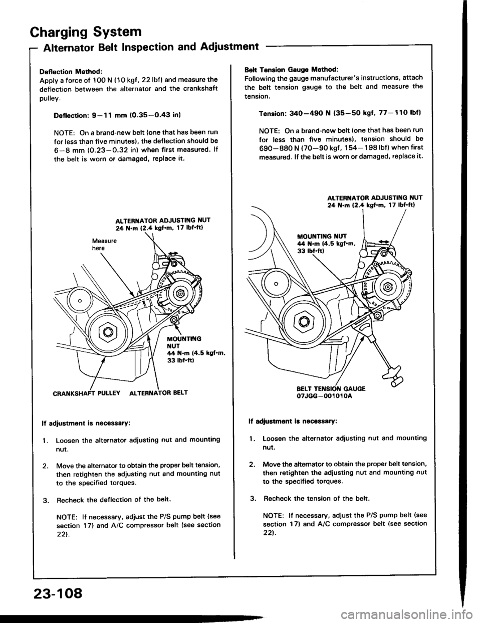
Charging System
Alternator Belt Inspection and Adjustment
Deflection Method:
Apply a force of 100 N (1o kgt, 22 lbJ) and measure the
deflection between the alternator and the crankshatt
pulley.
Detlsction:9-11 mm (0.35-O.43 inl
NOTE; On a brand-new belt {one that has be€n run
for less than five minutes), the deJlection should be
6-8 mm 1O.23-O.32 in) wh€n first measured. lf
the belt is worn or damaged, replace it.
ALTER'{ATOR ADJUSTIT{G NUT
24 N.m {2.4 kgl'm, 17 lbl'ft1
MOUt{Tlt{GNUT44 t{.m (4.5 kgt.m,33 tbf.ft)
PULLEY ALTEBNA
lf adiustment is nocessarY:
1. Loosen the alternator adjusting nut and mounting
nur.
2. Move the alternator to obtain the proper belt tension,
then retighten the adjusting nut and mounting nut
to the specified torques.
3. Recheck the deflection ot the belt.
NOTE: lt necessary, adiust the P/S pump belt (see
section 17) and A/C compressor belt lsee section
22t.
23-108
Boh Tsnsion Gaug6 Mothod:
Foltowing the gauge manuJacturer's instructions, attach
the belt tension gauge to the belt and measure the
tension.
Tension: 340-49O N (35-50 kgl, 77-110 lbfl
NOTE: On a brand-new belt (one that has been run
for less than tive minutes), tension should be
690-880 N (70-90 kgt, 154- 198 lbJ) when tirst
measured. lf the belt is worn or damaged, replace it.
lf adi$tmsnt is nscaasary:
1. Loosen the alternator adiusting nut and mounting
nut.
2. Move ths ahernator to obtain the proper bslt tension,
then retighten the adjusting nut and mounting nut
to the specified torques.
3. Recheck the tension of the belt,
NOTE: lf necessary, adjust the P/S pump belt (see
section 17) and A/C compressor belt (see section
22t.
ALTERI{ATOR ADJUSTING NUT
24 .ln 12.4 kst'm, 17lbl'ft}
oTJGG-0O1010A