Page 421 of 1413
E Position
As the engine turns, the oil pump also starts to operate. Automatic transmission fluid (ATF) is drawn from (99) and dis-
charged into (1 ). Then, ATF pressure is controlled by the regulator valve and becomes line pressure ( 1 ). The torque con-
verter inlet pressure (92) enters (94) of torque converter through the orifice and discharges into {90}.
The torque converter check valve prevents the torque converter pressure from rising'
Under this condition, the hydraulic pressure is not applied to the clutches.
NOTE:. When used, "left" or "right" indicates direction on the llowchart
. SOL-@: Shift Control Solenoid Valve A
' SOL{D:Shift Control Solenoid Valve B
. SOL@: Lock-up Control Solenoid Valve A
. SOL-@: Lock-up Control Solenoid Valve B
(cont'd)
14-29
Page 437 of 1413
Component Location
)/
,/s\
{7v
A0t
AUTOMATIC TRANSAXLE IA/TIGEAR POSITION SWITCH
VEHICLE SPEEDSENSOR {VSSI
COUNTERSHAFTSPEED SEf{SORMAINSHAFT SPEEDSENSORTHROTTLE POSITION (TP}SENSOR
at
,
)''ENGINE COOLANT TEMPERATURE (ECTISENSOR
14-45
Page 485 of 1413

Fluid Level
Checking/Changing
Checking
NOTE: Check the fluid level with the engine at normal
operating temperature (the cooling lan comes on).
1. Park the car on level ground. Shut otf the engine.
2. Remove the dipstick (yellow loop) from the trans-
mission, and wipe it with a clean cloth.
3. Insert the dipstick into the transmission.
DIPSTICK (YELLOW LOOPI
4. Remove the dipstick and check the fluid level.
should be between the uoDer and lower marks.
P
il
\---
T
lf the level is below the lower mark, add fluid into
the tube to bring it to the upper mark. Use Honda
Premium Formula Automatic Transmission Fluid or
anequivalentDEXRON@ llAutomaticTransmission
Fluid (ATF) only.
lnse.t the diDstick back into the transmission.
IT
{J. UPPER MARK
t)-i- LowER MARK
5.
6.
Changing
1. Bring the transmission up to operating temperature
by driving the car. Park the car on level ground, turn
the engine oft, then remove drain plug.
NOTE: lf a cooler flusher is to be used, see page
14-168 and 169.
2. Reinstail the drain plug with a new sealing washer,
then refillthe transmission to the upper mark on the
dipstick.
Automatic Transmission Fluid Capacity:
2.1 | l2.S US qt, 2.4 lmp qt) at change
5.9 ? (6.2 US qt, 5.2 lmp qt) at overhaul
18 x 1.5 mm49 N.m (5.0 kgl.m, 36 lbl.ft)
TRANSMISSION RIGHT SIDE COVER
14-93
Page 492 of 1413
Transmission
Removal {cont'd)
7. Remove the transmission housing mounting bolts.
Remove the drain plug and drain the automatic trans-
mission tluid (ATF). Reinstall the drain plug with anew sealing washer lsee page 14-93).
DRAIN PLUG18 x 1.5 mm49 N'm 15.0 kgt-m,36 tbt-fr)
9. Remove the splash shield.
6 x 10
CLIPS pcs.
10. Remove the cotter pins and castle nuts, then
separate the balljoints from the lower arm {see sec-
tion 18).
11. Remove the right dampe. fork bolt. then separate
right damper fork and damper.
PINCI{ BOLT
SELF.LOCKINGNUTReplace.COTTER PINReplace.
/\
14-100
DAMPER FORK
CASTLE NUT
Page 561 of 1413

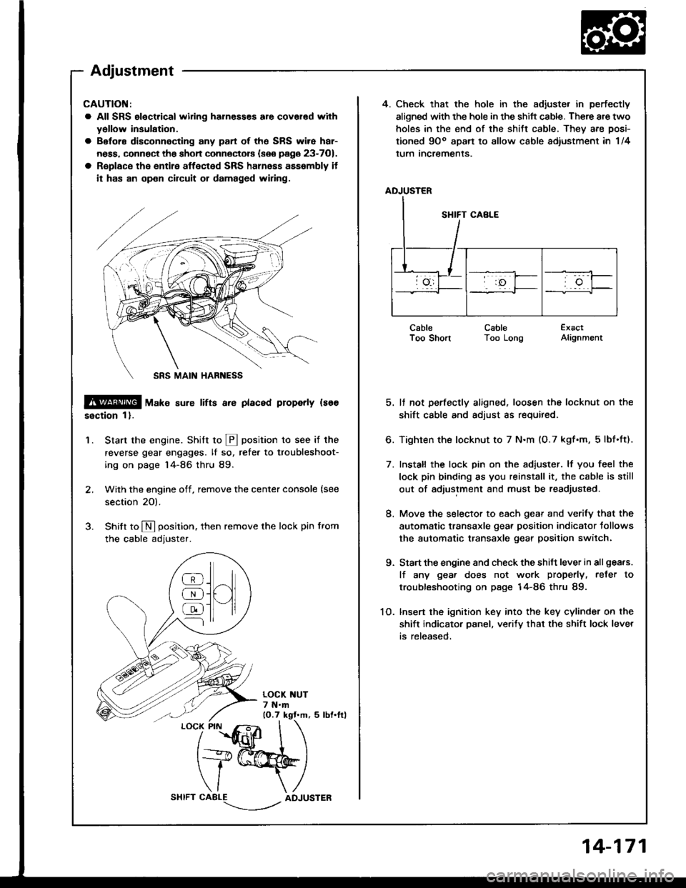
4. Check that the hole in the adiuste. in perfectly
aligned with the hole in the shift cable. There are two
holes in the end of the shitt cable, They are posi-
tioned 9Oo apart to allow cable adiustment in 1/4
lurn Incremenls.
ADJUSTER
CableI oo snonCableToo LongExactAlignment
5. It not perfectly aligned, loosen the locknut on the
shift cable and adjust as required.
6. Tighten the locknut to 7 N.m (O.7 kgf.m, 5lbf.ft).
7. Install the lock pin on the adiuster. lf you feel the
lock pin binding as you reinstall it, the cable is still
out of adjustment and must be readjusted.
8. Move the selector to each gear and verify that the
automatic transaxle gear position indicator tollows
the automatic transaxle gear position switch.
9. Start the engine and check the shift lever in all gea.s.
lf any gea. does not work properly, refer to
troubleshooting on page 14-86 thru 89.
1O. lnsert the ignition key into the key cylinder on the
shift indicator panel, ve.ify that the shift lock lever
is released,
CAUTION:
a All SRS electrical widng harn€sses are covar€d with
yollow insulation.
a Before disconnecting any part of ths SRS wire har-
ness, connect the shon connectors (see page 23-701.
a R€place the entire affected SRS halnass asssmbly it
it has an op€n circuit or damaged wiring.
@ tu"t" sure lifts a.e placed properly ls66
ssction 1).
Start the engine. Stritt to @ position to see if the
reverse gear engages. lf so, refer to troubleshoot-
ing on page 14-86 thru 89.
Wilh the engine off, remove the center console {see
section 20).
Shilt to N position. then remove the lock pin from
the cable adjuster.
'1.
/
''fidlfr
I
t+@
\/ \
CABLE-.'.-_--l../ADJUSTER
]H
@
@
@
Adjustment
14-171
Page 562 of 1413
Gearshift Selector
Disassembly/Reassembly
CAUTION:
a All SRS electrical wiing haln€ssss are covered withy6llow insulation.
a 8€fore disconnecting 8ny pan of the SRS wire har-
neaa. connOct th6 short connectors (sse page 23-701.
a Roplace the entire affected SRS hahess assembly if
il has an opon circuit or damaged wiring.
9.8 N.m {1.O kgf.m, 7.2 lbf.frl
SHIFT LOCK SOLENOID
CONTROL BRACKET
SELECT LEVER BRACKET
CONTROL SEAL
SRS MAIN HARNESS
[E--__ rocK ptN
ADJUSTER
-6{stLtcoNEGREASEe-LEVER COVER
LOCK PIN ROD
-#qSILICONE GREASE
@6
5 N.m (0.5 kgt.m, 4 lbt.ftl
AUTOMATIC TRANSAXLEGEAR POSITION SWITCHTesting, see Section 23
9.8 N.m (1.0
7 .2 tbt.ltl
12 N.m (1.2 kgf.m, 8.7 lbf.ftl
9.8 N.m 11.0 kgf'm,7.2 lbf.ftl
14-172
Page 567 of 1413
Differential
Manual Transmission
81881 engine
818C1 engine .......
Automatic Transmission ..................
15-1
15-9
15-19
Page 585 of 1413
Differential (Automatic Transmissionl
Special Tools ........ ........ 15-20
Differential (Automatic Transmission)
flfustrated Index......... .15-21
Backfash Inspection .... 15-22
Bearing Replacement ............... ..... 15-22
Differential Carrier Replacement .... 15-23
Oil Seaf Removal ........15-24
Oil Seal Installation/
Side Clearance ............. 15-24