1994 HONDA INTEGRA Automatic
[x] Cancel search: AutomaticPage 109 of 1413

Timing Belt
lnspection
Remove the cylinder head cover.
. Refer to page 6-78 when installing.
Inspect the timing belt for cracks and oil or coolant
soaking.
NOTE:
. Replace the belt if oil or coolant soaked.
. Remove any oil or solvent that gets onthe b€lt.
Rotate pulleyand inspect b6lt.
After inspecting. retorque the crankshaft pulley bolt
to 177 N.m (18.0 kgf.m, 130 lbf.ft).
Tension Adjustment
CAUTION: Always adlust timing bslt tsnsion with th6
engine cold.
NOTE:
. The tensioner is spring-loaded to apply proper ten-
sion to the belt automatically after making the follow-
ing adjustment.
a Alwavs rotate the crankshaft counterclockwise when
viewed trom the pulley side. Rotating it clockwise
may result in improper adjustment of the belt ten-
sion.
Remove the cylinder head cover. (Refer to page 6-
78 when installing.)
Set the No. 1 piston at TDC (see page 6-51).
Rotate the crankshaft 5-6 revolutions to set the belt.
Set the No. 1 piston at TDC.4.
AINUSTING AOLT5/a N.m 15.5 kg{.m, to lbtftlFor adjustment only,
5.
7.
8.
A
.//\v-/
Directionrotat|on,
Loosen the adjusting bolt 1/2 turn (180') only.
Rotate the crankshaft counterclockwise 3 teeth on
the camshaft pulley.
Tighten the adjusting bolr.
After adjusting, retorque the crankshaft pulley bolt
to 177 N.m (18.0 kgf.m, 130 lbf'ft).
6-48
Page 143 of 1413

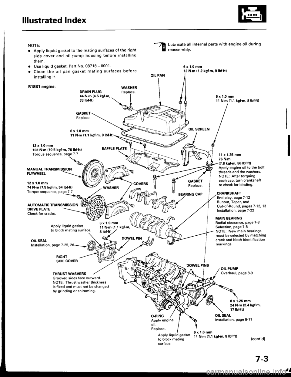
lllustrated Index
NOTE:
. Apply liquid gasket to the mating surfaces of the right
side cover and oil pump housing before installing
them.
. Use liquid gasket, Pan No.08718 - 0001.
. Clean the oil pan gasket mating surfaces before
installing it.
Bl8Bl engine: wAsHEF
Lubricate all internal parts with engine oil during
reassemory.
6x1.0mm12 N.m (1.2 kgf.m,I lbf.ftl
6x1.0mm11 N.m (1.1 kgf.m,8lbtft)
OIL SCREEN
11 x 1.25 mm76 N.m17.8 kgl.m, 56 lbf ftlApply engine oilto the bolt
threads and the washers.NOTE: After torquingeach cap, turn crankshaftto check lor binding.
DRAIN PLUG44 N.m {4.5 kgf.m,33 tbtfr)
GASKETReplace.
6x1.0mm1'l N.m {1.1 kgt.m, I lbtft)
OIL PAN
O.RING
GASKETReplace.
BEARING CAP
12 x 1.0 mm103 N.m (10.5 kgf.m, ?6lbf ft)
MANUALFLYWHEEL
'12 x 1.0 mm74 N.m {7.5 kgt m,54lbf.ftlTorque sequence, page 7 7
DRIVE PLATECheck for cracks,
AUTOMATIC TRANSMISSION
WASHER
6x1.0mm11 N.m {1.1 kgl.m,8 tbf.frt
CRANKSHAFTEnd play, page 7-12Runout, Taper, andOut-of-Round, pages 7 12, 13Instsllation, page 7 22
MAIN BEARINGRadial clearance, page 7-8
Sel€ction, page 7-8NOTE: New main bearingsmust be selected by matching
crank and block identificationmarkrngs.
Apply liquid gasket
to block mating surface.
OIL SEALInstallation, page 7-25,
RIGHTSIDE COVERDOWEL PINSOIL PUMPOverhaul, page 8-9THRUST WASHERSGrooved sides face outward.NOTE: Thrust washer thicknessis tixed and must not be changedby grinding or shamming.
8 x 1 .25 mm2,1 N.m {2.4 kgt m,17 tbt.ft)
OIL SEALInstallation, page 8-11Apply engrneorl.Replace.
Apply liquid gasket
to block mating
6x1.0mm'11 N.m {1.1 kgf'm, 8 lbl ft)(conr'dl
7-3
Page 147 of 1413

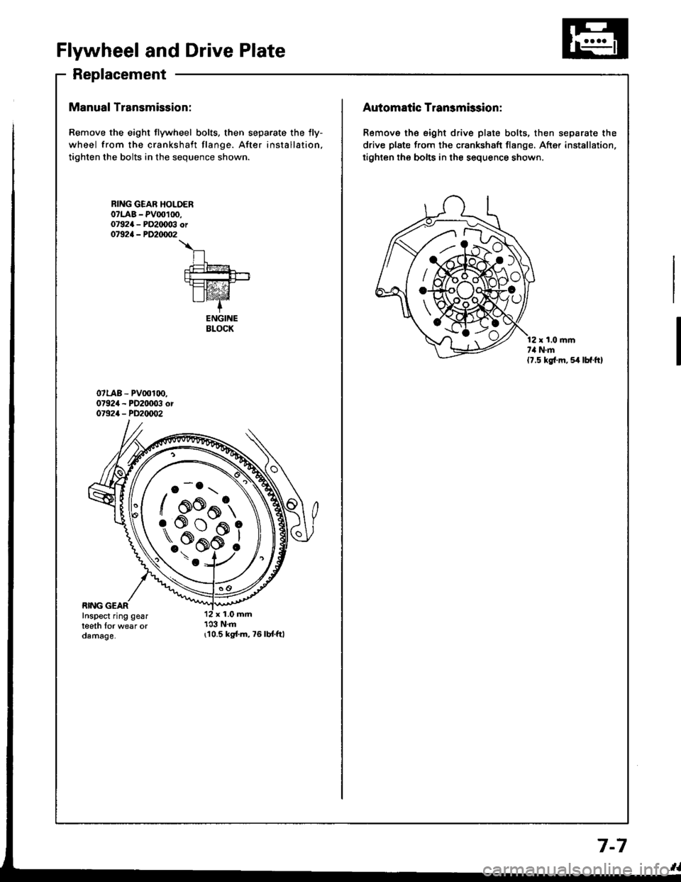
Flywheel and Drive Plate
Replacement
Manual Transmission:
Remove the eight flywheel bolts, then separate the lly-
wheel from the crankshaft flange. After installation,
tighten the bolts in the sequence shown.
r10.5 kgi.m,76lbt.ftl
RING GEAR HOLOERo?LAB - PV00100,07924 - PO2IX)03 or07924 - PD20/m�2
\
n.t=?4
fut!!-+-rt=tz-21I lvaz'Z-+
ENGINEBLOCK
o -o.r \
/ oo^t,
\..?bi
/ AK{:{AAo
rs#*ffi_9
Automatic Transmission:
Remove th€ eight drive plate bolts, then separate the
drive plate from the crankshaft flange, After installation,
tighten the bolts in the sequence shown.
r t.0 mmt,l N.m(7.5 kg{.m, 54 lbf.ft}
7-7
Page 186 of 1413

lllustrated Index
@ sy"t". is under high plessure when engine
is hot. To avoid dsnger of relsssing scalding engine
coolant. remove cap only when engine is cool.
Total Cooling System Capacity (lncluding heater and
r€servoirl
Bl8Bl engine:
Mfl: 6.4 | {6.8 US qt, 5.6 lmp qt}
AlTt 6.7 | {7.1 US qt, 5.9 lmp qt}
Bl8Cl engine:
Mfi: 6.7 t {7.1 US qt, 5.9 lmp qt}
CAUTION: lf any engine coolant spills on paint€d por-
tions ot the body, rinse it ofl immediately.
NOTE:
a Check all cooling system hoses for damage. leaks or
deterioration and replace if necessary.
a Check all hose clamps and retighten if necessary.
a Use new O-rings when reassembling.
CONDENSERFAN SHROUD{soe soction 221
6 x 1.O mm7 N.m (O.7 kgt.m. 5 lbf.ftl
ATF COOLERHOSES{81881 6ngine)
RADIATOREngine coolant refilling and bleeding,page 10-5Leak test, page 'l0-6
Inspect soldered joints andseams for leaks.Elow out dirt from betweencore fins with compressed air.lf insects, etc., are clogging.adiator, wash them off withlow pressure water,
S!
P
R
U
COOLANTRESERVOIR
5x0.8mm4.4 N.m (O.45 kgf.m,3.3 lbl.fr)
M/T: Manual t.anamiaaionA/T: Automatic t.ansmiasionATF: Automatic t.ansmission fluid
\*
*)
FAN SHROUD
10-2
Page 194 of 1413

Fuel and Emissions
Spocial Tools ................ 1 1-2
Compon€nt Location
lndex ................. ...... 11-3
System Description
Vacuum Connectiona .......,.................... 1 1 -8
Efectrical Connections ....,.,.,......,...,,.....,'11-12
Syst€m Connectors ...,...,.................-.--. 11-2O
T.oubloshooting
Troubleshooting Guido .......................... 1 1-32
Self -diagnostic Procedures .,..,............... 1 1 -34
How to Road Flowcharts ...................,... 11-39
PGM-Fl System
Systom Description .............................. 1 l-4O
Troubleshooting Flowcharts
Engine Control Moduls ............... ........... 1 1 -42
Heated Oxygon Sensor ......,.................. 1 1-46
Heated Oxyg€n Sonsol Heatel .....,......... 1 1 -47
Fuel Supply System ..............-............... 1 1-50
Manitold Absolute Pressure
Ssnsor ............................................ 1 1-52
Top D6ad Cente./Crankshatr
Position/Cylindor Position sonsor ........ 1 1 -56
Engine Coolant Tempsrature Sonsor ....... 11-58
Throttlo Position Sonsor ........,..,,........... 1 1-60
Intake Air Temperaturs Sensor ............... 11-62
Baromet c Prsssuro Sensor ......,...,...,..,. 11-64
lgnition Output Signal ........................... 1 1 -66
Vehicle Spe€d Sensor ........................... 1 1 -68
Electdcal Load Dotector ....,...,..........,.... 1 1 -7O
Knock Sensor [818C1 engine] ............... 11-74
A/T Fl Signal A/B ................................. 1 1-76
ldle Contlol System
System Troubleshooting Guide .................. 1 1 -78
Systom Description ........ 11-79
Troubloshooting Flowchans
ldl€ Ail Control Valve ........................... 1 1 -82
Ail Conditioning Signal ......................... 1 1 -84
Altemator FR Signal ............................. 1 1 -86
Automatic Transaxle (A/T) Gear
Position Signal ......... 11-88
Brake Switch Signal ............................. 1 1 -9O
Startel Switch Signal ............................ 11-92
Power Steering Pressure Switch Signal ... 11-93
Fast ldle Thermo Valve ...................,......... 1 1 -94
ldls Speed S€tting .................................... 1 1 -95
Fuel Supply System
Systam Tloubloshooting Guid. .................. 1 1 -97
Fuol Linos ...................... 1'l -98
System Description ........ 11-100
Fuol Prassure ................. 11-100
Fu6l Ini6ctors ................. 11-102
Fuel Pressure Ragulato. .,. 11-106
Fuel Filter ...................... 11-108
Fual Pump ..................... 11-109
PGM-Fl Main F6lay ................................... 1 1"1 1 1
Fuel Tank ...................... t 1-114
Intake Air System
System Troubloshooting Guido .................. 1 1 -1 1 5
Systom Dascription ........ 11-116
Air Clean€r .................... 11-117
Throttls Cable ................'11-118
Throttl8 Body ................ 11-120
lntake Air Bypass Cont.ol Systsm
[B18Cl enginal .,......... 11-123
Intake Manilold [B1881 onginol ................. 11-128
Emission Control System
Systsm Troubleshooting Guido .................. 1 1 -1 29
Systam Doscription ........ 11-130
Tailpips Emission ........... 11-130
Thrae Way Catalytic Convortor ...,...,........., 11-131
Positiva CrankcaEo V6ntilation Systcm .,....., 11-134
Evaporativo Emission Contro|,..,..,.,.,,.,,..,.., 1 1-135
Page 238 of 1413

PGM-FI System
Heated Oxygen Sensor lHO2Sl
ztRcot{lAELEiIE'{T
HEATER
- --.'!- - -__-
lrPl _l !l-
-fi-l: The Malfunction Indicator Lamp (MlL) indicates Diagnostic Troubls Code (DTC) 1: A problsm in
/? the Heated Oxygen Sonsor (HO2S| circuit.
The Heated Oxygen Sensor IHO2S) det€cts th6 oxygon contont in th6 exhaust gas and signals th6 ECM. In operation,
the ECM receiv€s th6 signals trom the sensor and vari€s the duration during which tu6l is iniocted. To stabilize thd sen-aor's output, tho sensor has 8n intarnal heater and the sensor olemant is coatod with a catslyst. The HO2S is installod
in TWC housing (B18Cl engine) or exhaust pipe B (Bl8Bl €ngine).
sEl{SORTERMII{ALS
:tz-t6l-/ --.- \
VOLTAGE (V}sTotcHtoltETncAIR-FUEL BANO
HEATEBTEBMIT{ALSRICH - AN. - LEAI{FUELRATIO- Th! mll h.. bo.n raportad on.- Wlth thr SCS rhon coon cto.connoctad lr.. p!9. 1t-341,cod. t l. Indlcltrd.
Oo th€ ECM Res€t Procodure {soopag€ 11-35).
Stan the 6ngine. Hold th6 engine
A3,qgq rpm with no load {A/T in
Lryl or lll position, M/T in nourralluntil the radiator lan com6s on.then lot it idle lor ot least on6minutg beforo road t€6tin0.
Connoct ths SCS short connoctorto th6 sorvic€ check connectorlsoo p.g6 1 1-34).
Rood t€st witlthe automatictransmission in L?l position (M/T:4th gear).Stsrting st l,600 rpm, acc6lorateu6ing wide open throttlo for atlesgt 5 seconds. Thsn dgcol€rstefor at lorst 5 s€conds with th€throttlo completoly closed.
Intarmittd[ t llurc, lyri.m b Of!l thla tlmc. Ch.ck lor poor con-nacdona o? loota wlrat |l C223(loc.trd at right $ock towo.l,Cr 13 (HO2S| lnd ECM.
Ooes the MIL blink and doos itindic6t6 cod6 1?
Go to plga and partonn tad fotcod. 43 lr.a p.go l1-501.
1 1-46
Page 267 of 1413

ldle Gontrol System
System Troubleshooting Guide
NOTE:
a Acrosa each row in the chan, the sub-systems that could be sources of a symptom are ranked in the order they should
be inspected, starting with O. Find the symptom in the left column, read across to the most likely source, then reler
to the page listsd at ths top ot that column. It inspection showa the system is OK, try the next system @, etc.
a lf the idle speed is out of sp€cification and th€ Malfunction Indicator Lamp {MlL) does not blink Diagnostic Trouble
Code (DTC) 14, 9o to inspection describ€d on pags 1 1-81.
PAGE
SYMPTOM
IDTIOJUSTIiSCREW
IDLE AIRc0NTROt-
AIRcoN0fTtoNtitcSIGNAL
ALTER.NAION FNSIGNAL
AUTOMATICIRAI{SA(LEGtARP0sm0 stGIAt
ERAK€swrTcHSIGNAL
STARTERswtTcHSIGNAT
POWERSTEERII'IGPffESSUREswncHSIGNAL
FAST IOLETHERMO
HOSESANOCONNEC.TIONS
11-9511-4211-841 1-8611-8811-9011-92I 1-9311-94
DIFFICULT TO STARTENGINE WHEN COLD@o
WHEN COLD FAST IDLE OUT OFSPEC l1,0OO- 2,0OO rpm|o@o
ROUGH IDLEo
WHEN WARM RPM TOO HIGHooo
WHEN
TOO LOW
ldl6 3p6od b b€lowspecitisd rpm (no loadl@o
ldla 5p66d doos nolincraas€ alter initialo
On mod6l3 with auto-matic transmBsion, thsidlo sp€ed drops in 963ro
ldl6 sp€eds drops when8ir condilioner in ONoo
ldls spo6d drops when6ts6iing wh66l i6 turninC@o
ldla spoed lluctust63with alactrical loado
FREOUENTSTALLING
WHILE WARMING UP@o
AFTER WARMING UPo@
FAILS EMISSION TESTo
11-78
.,Hilffirl|,
Page 277 of 1413

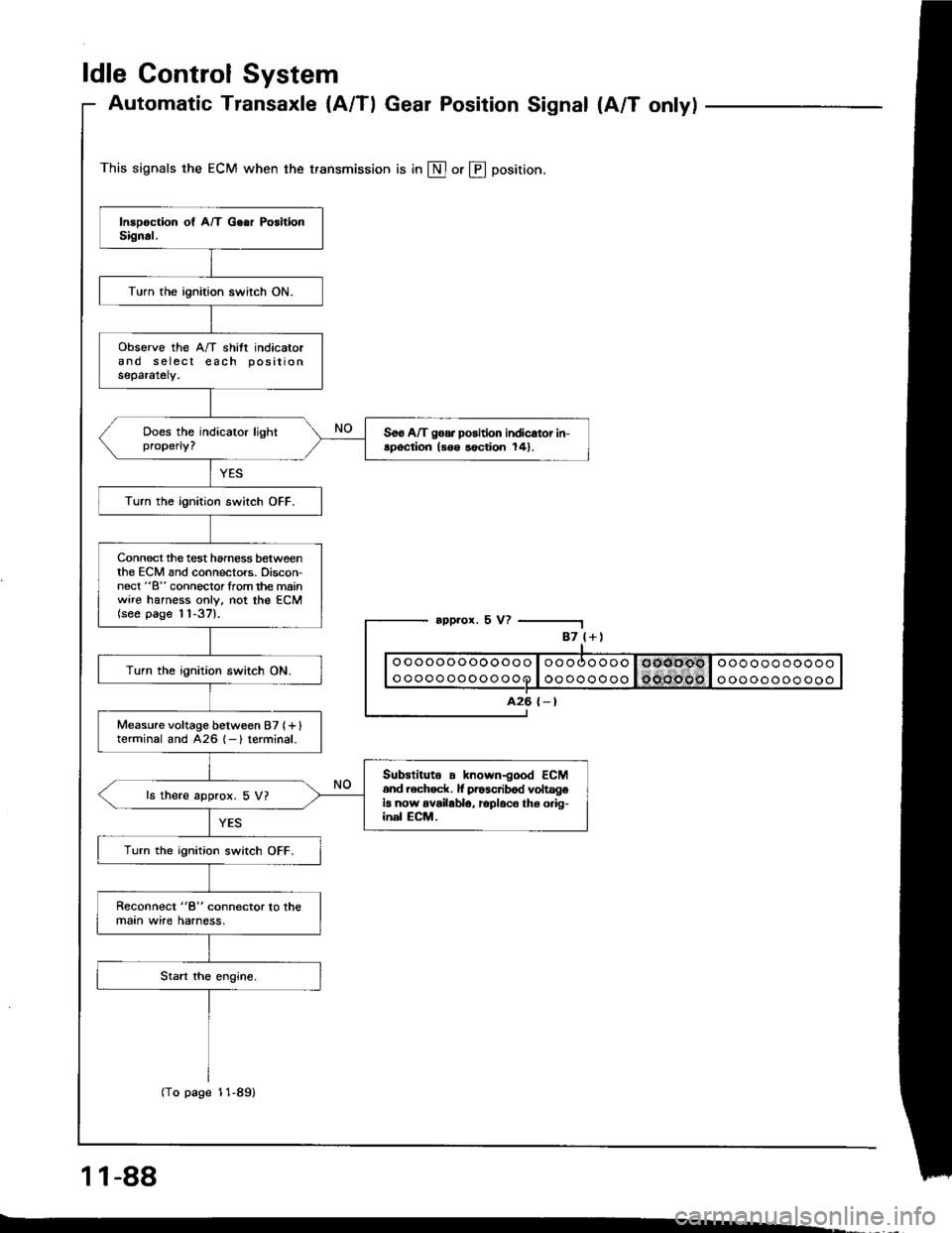
ldle Control System
Automatic Transaxle {A/Tl Gear Position Signal {A/T onlyl
This signals the ECM when the transmission is in @ or @ position.
appror. 5 V?
1 1-88
-.
87 l+)
ooooooooooooo
oooooooooooo
A26 {-}
Turn the ignition switch ON.
obsorve the A/T shift indicatorand s eiecl each positionseparately.
Soo A/T goa. position indicator in-spoqtion ls6o lection 141.
Turn the ignition switch OFF.
Connect the test hamess betweenthe ECM and connectors. Discon-nect "B" connoclorlrom the mainwire harness only, not the ECM(see page 11-37).
Turn the ignition switch ON.
Measure voltage between 87 (+ Iterminal and 426 1- ) terminal.
Subslituto . known-good ECM6nd .ech6ck. lf pr63cribod voltageia now availablo, rcplaco ths o.ig-inel ECM.
ls there approx. 5 V?
Turn the ignition switch OFF.
Reconnect "8" connector lo lhemaan wire harness.
(To page 11-89)