Page 1278 of 1413
Ceiling/Trunk/Gargo Area Lights, Spotlights
Component Location Index
23-172
r 1: Sedanr2: Hatchback
CEIIING LIGHTTest/Replac€mont. page 23-175
SPOTLIGHTSTest/Rsplscement, page 23-1 7 4
.1 LEFT REARDOOR SWTCHTest. page 23-150
FRONTPASSEl{GER'SDOORswtTcHTest, pago 23-150
*2 HATCH LATCHswtTcHTest/Replacement,page 23-178
11 RrcHT BEARDOOR SWrCHTost. page 23-150
11 TRUNK LATCHSWITCH '1 TRUI{K LIGHTTest/Replac€ment, Test/Replacemontpage 23-178 Page 23-177
rII-
Page 1280 of 1413
Ceiling/Trunk/Cargo Area Lights, Spotlights
Spotlight Test/Replacement
23-174
1. Turn the light switch OFF.
2. Pry off the lens.
3, Remove the two screws, then pull out the housing.
Hatchback:
4.
5.
Disconnect the connector from the housing.
Check for continuity between the terminals in each
switch position according to the table.
Sedan:
CONNECTOR
Torminal
;r,,-
----lABorB'CorC'
tEFrONo-/:\--o\:/
OFF
RIGHTONo---o
OFF
"" li ** li
B'O B
BULB
-FFmlliF-T
Page 1282 of 1413
Geiling/Trunk/Cargo Area Lights' Spotlights
Geiling Light Test/Replacement
Without moonroot:
1. Turn the light switch OFF.
2. Pry ofJ the lens.
3. Remove the sctew, then pull out the housing'
4. Disconnect the 3-P connector from the housing.
3-PCONNECTOR
23-176
T6ninsl
P"riti"" \
ABor B'D
OFFo-/:\--o\:.,/
DOORo-A--o
ONLF/A--o
5. Check for continuity between the terminals in each
switch position according to the table.
F om o.3l7.5Al FUSEtln thr uid.r - ddr h|. /,.LY borlA
Page 1283 of 1413
Trunk/Cargo Area Light Test/Replacement
Pry the trunk/cargo afea light lens out of its housing.
Pry out the light assembly.
Disconnect the 2-P connector trom the housing.
Hatchback:
2.P CONNECTOR
BULE 13.4 Wl
A {+}B {-)
HOUSING
BULB {3.4 W)
2.P CONNECTOR
4. Make sure that the bulb is in good condition. Checkfor continuity between the A (+) and B (-ltermi-
nals. There should be continuitv (Hachback: theswitch must be Dushed).
Hatchback:
Sedan:
Froh o.3 (7.5A1FUSE
{ln th. undor - d!.hfur./r.hy box)
To HATCHLATCHswtTcH
F om o.3 (7.5A1FUSE
{ln th. und.i- da.htur€/r.hy box)
To TRU KLATCHswtTcH
23-177
Page 1284 of 1413
Ceiling/Trunk/Cargo Area Lights, Spotlight
Latch Switch Test/Replacemsnt
Sedan:
1. Open the trunk lid. and disconnect the 2-P connec-
tor from the trunk latch switch.
2. There should be continuity between the A and B ter-
minals.
ll necessary, remove the three mounting bolts to pull
out the trunk latch switch from the trunk lid, then
disconnect the lock rod from the trunk latch switch.
Disconnect the trunk opener cable from the trunk
latch switch.
4.
\j
CC
TRU'{K OPG ER
TRUNK LATCH SWITCH
lhtchb.ck:
1 . Op6n the hatch, and disconnect the 2-P connector
trom the hatch latch switch.
2. There should be continuity between thg A terminal
and component ground.
lf necessary, remove the three mounting bolts to pull
out the hatch latch switch trom the latch, then dis-
connact the lock rod Jrom the hatch latch switch
Disconnect the hatch opener cable trom the hatch
latch switch,
3.
4.
23-178
Page 1289 of 1413
High Mount Brake Light Replacement {Bulb type)
Hatchback:
1. Open the hatch.
2. Remove the two clips and the cover.
3. Remove the two nuts and the high mount brake light,then disconnect the 2-P connector.
Turn the socket 45o counterclockwise to remove thebulb.
Install the high mount brake light in the reverse or-
der of removal, and clean the rear window glass be-
tore installing.
CAUTION: Whon installing ih6 high mount brakelight. make sur6 the rubber soal fits against the realwindow ev6nly.
4.
Sadan:
1. Open the trunk lid, and disconnect the 2-P connec-
tor trom the high mount brake light.
2. Remove the two nuts, then remove ths high mount
brake light from the rear shelt.
2-P CONt{ECTOR
Install the high mount brake light in the reverse or-
der of removal. Clean the rear window glass before
installing rhe light.
2
23-183
Page 1299 of 1413
Rear Speaker Replacement
Hatchback:
1. Remove the sDsaker cover.
2. Remove the three screws, then disconngct the 2-P
connocter trom the rear spoakor.
1.Remove the three screws from the trunk side, then
remove the soeaker cover.
Remove the tour screws, then disconnect the 2-P
connector t.om the s9eaker, and remove the
soeake,.
LEFT REARSPEAKER
OUARTER
,r-- I
TRIM PAI{EL
LEFT REARSPEAKEN
2-P CONNECTON
SPEAKER COVER
REAB TRAY
SPEAKER COVER
23-193
Page 1300 of 1413

Stereo
Power
Sound
Antenna
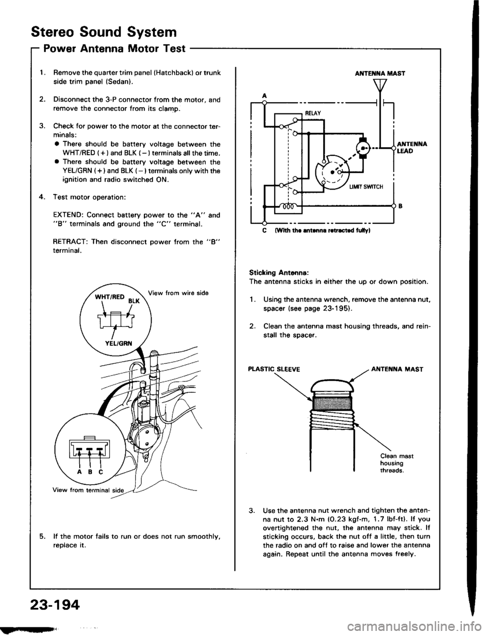
System
Motor Test
Remove the quarter trim panel (Hatchback) or trunk
side trim panel (Sedan).
Disconnect the 3-P connector from the motor, and
remove the connector from its clamD.
Check for power to the motor at the connector ter-
minals:
a There should be battery voltage between the
WHT/RED (+l and BLK {-} terminals all thetime.a There should be battery voltage between the
YEL/GRN {+) and BLK (-} terminals onlv with the
ignition and radio switched ON.
Test motor oDeration:
3.
4.
EXTEND: Connect battery power to the "A"
"B" terminals and ground the "C" terminal.
8no
"4"RETRACT: Then disconnect power trom the
terminal,
lf the motor fails to run or does not run smoothlv,
reDtace tr.
*ft'^to
?r*
TIFIT*r'
YEL/GRN
AI{TE T{A MAST
AI{TEI{I{ALEAD
C ftYhh lha lnLnn. r.tr.ci.d t|Ilyl
Sticking Ant6nna:
The antenna sticks in either the up or down position.
1.Using the antenna wrench, remove the antenna nut,
spacer (see page 23-195).
Clean the antenna mast housing threads, and rein-
stall the soacer.
PLASTIC SLEEVEAIITENNA MAST
Cloan masthousingthroads.
Use the antenna nut wrench and tighten the anten-
na nut to 2.3 N.m (0.23 kgf-m, 1.7 lbf-tt). lJ you
overtightened the nut. the antenna may stick. lf
sticking occurs, back the nut off a little, then turn
the radio on and off to raise and lower the antenna
again. Repeat until the antenna moves treely.
23-194
fmft,