1994 HONDA INTEGRA Trouble code
[x] Cancel search: Trouble codePage 608 of 1413

Steering
Special Tools ............. 17-2
Component Location
lndex ................ ...... 17-3
System Description
Ff uid Flow Diagram ......................... 17 -1
Steering Pump ................................. 17-5
Steering Gearbox ............................. 17-7
Troubleshooting
General Troubleshooting ................ 17-10
Noise and Vibration ......................... 17-14
Fluid Leaks ............. 17-16
Inspection and Adiustment
Steoring Operation .......................... 17 -14
Power Assist Check
with Car Parked ........................... 17-18
Steering Linkage and Gearbox ....... 17-19
Pump Beh .............. 17-20
Rack Guide Adjustment ............. ..... 17-21
Ff uid Replacement ...................... ..... 17 -21
Pump Pressure Check .................. .... 17 -22
Ffuid Leakage lnspection ................ 17-23
+ Steering Wheel
Removal ..,,,,,,,........ 17-24
Disassembly/Reassembly ............... 17 -25
fnstallation ,......,,,,,. 17-26
* Steering Column
Removaf .................17-28
Inspection .............. 17-30
Installation ............. 17-31
Power Steering Hoses. Pipes
Replacemont ......... 17-3tl
Power Steering Pump
Removal ................. 17-35
Disassembly .......... 17-35
Reassembly ........... 17-'10
lnstallation ........,..., l7-tltl
Steering Gearbox
Removaf .,.,............. 17-45
Disassembly .......... 17-/E
Reassembly ........... 17-53
lnstallation ............. 17-63
Ball Joint Boot Replacement .......... 17-65
SUPPLEMENTAL RESTRAINT SYSTEM {SRSI
The Integra SRS includes a driver's airbag. located in the steering wheel hub, In addition, all models except the
RS model for Canada have a front passenger's airbag located in the dashboard above the glove box. Information
necessarv to safely service the SRS is included in this Service Manual. ltems marked with an asterisk {') on the
contents page include, or are located near, SRS components. Servicing. disassembling or replacing these items
will require special precautions and tools, and should therefore be done by an authorized Acura dealer.
a To avoid rsndering ths SRS inoporative, which could load to po.sonal iniury 01 d€ath in th€ event ot a ssvare
lrontal collision, all SRS service work muat be performod by an authorizod Acura deal6t.
a lmploper service procodules. including incorloct romoval and installation of the SRS, could lead to personal iniu-
ry caused by unintontional activation ot the airbags.
a All SRS elsctdcal wiring harnesses ara covorod with ysllow insulation. Rolalod compon€nts 8re locatsd in tho
stse ng column, tront console, dashboard, and dashboard lower panel, and in the dashboard above the glove
box. Do not use oloctrical tost equipmoni on thosa cilcuits.
NOTE: The original radio has a coded thett protection circuit. Be sure to get the customer's code number before
- disconnecting the battery.- removing the No. 32 (7.5 A) tuse from the under-hood fuse/relay box.
- removing the radio.
Alter service, reconnect power to the radio and turn it on. When the word "CODE" is displayed' enter the cus-
tomer's 5-digit code to restore radio operation.
Page 1109 of 1413
Troubleshooting
Tips and Precautions
Before Troubloshooting
a Check applicable fuses in the appropriate fuse/relay
DOX.
a Check the battery for damage, state of charge, and
clean and tight connections.a Check the alternator belt tension.
CAUTION:
a Do not quick-charg€ a battery unless the batteryground cabla has be€n disconnoctsd. oth€rwisoyou will damage the alternator diodss.a Do not att6mpt to crank the engine with the bat-tery ground cable loosely connectsd or you will se-vorsly damag€ tho widng.
a The original radio has a codod thatt plotection ci.-cuit. Be sul€ to got tho customor's code numbet
before- disconnecting th€ battery.- lomoving tho No. 32 (7.5 Al tuso f.om the
under-hood tuse/lelay box.- removing tho radio.
Aflor s€lvic€. reconn€ct powet to tho radio and
turn it on. Whon the word "CODE" is displayed,
€nt€l the customer'E s-digit codo to .astore ladio
operation.
Handling Connectors
a Make sure the connectors are clean and have no loose
wire terminals.
a Make sure multiple cavity connectots are packed withgrease (except watertight connectors).a All connectors have push-down release type locks.
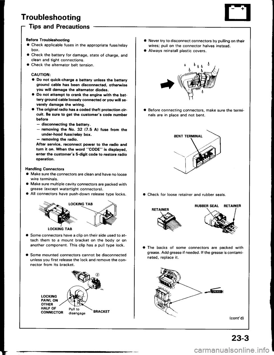
LOCKII{G TAA
LOCKING TAB
a Some connectors have a clio on their side used to at-
tach them to a mount bracket on the body or on
another component. This clip has a pull type lock.
a Some mounted connectors cannot be disconnected
unless you first release the lock and remove the con-
nector from its bracket.
LOCKINGPAWL ONOTHERHALF OFPull toorsengageCONNECTORBRACKET
23-3
a Never try to disconnect connectors by pulling on thei.
wires; pull on the connector halves instead.
a Always reinstall plastic covers.
Belore connecting connectors, make sure the lermi-
nals are in Dlace and not bent.
a Check tor loose retainer and rubber seals.
RETAINER
a The backs of some connectors are oacked with
grease. Add grease if needed. It the grease is contami-
nated, reDlace it.
(cont'd)
Page 1112 of 1413
Troubleshooting
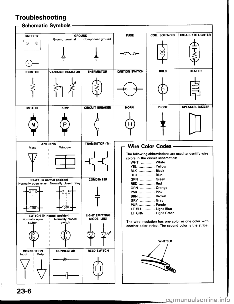
Schematic Symbolsym
BATTERY
le @l
ll
e-
GROIGround terminal
I
,ltDComponont ground
I
FUSECOIL, SOLENOID
H
CIGANETTE LIGHTER
A
t+j
RESISTOR
+
VARIABLE RESISTOR
ilH
THERMISTOR
e
tcNtTtol{ swTcH
-1o oF
BULB
e
HEATER
H
MOTOR
a
PUMP
0
CIRCUIT BREA(ER
I
T
HORI'
+
DIODE
+
SPEATER, BUZZER
D
Mast
Y
ANTIINNATRA SISTOR lTrl
II
Wire Golor Codes
The tollowing abbreviations are used to identity wire
colors in th€ circuit schematics:
wHT ............ White
YEL .............. Y6llow
BLK .............. Black
BLU .............. Blue
GRN ............. Green
RED.............. Red
ORN ............. Orange
PNK .............. Pink
BRN .............. Brown
GRY ............. Gray
PUR .............. Purple
LT BLU ......... Light Blue
LT GRN ......... Light Gr€en
The wi.e insulation has one color or one color with
another color stripe. The s€cond color is the stripe.
WHT/ALK
,/t,/l./l--
R
RELAY {ln noNormally open relayrmal poritionl
Normally closed relay
*Gt-i- |
lll
l'*^f
CO'IDENSER
I
T
SWITCH (ln ngrmal position)
Normally open ' Normally closodswitch I switch
til
@@
lil
LIGHT EMITTINGDIODE (LEDI
A[,
TT
CONNEInpur
f7
I
CTIONOutput
I\/
CONNECTON
--+>-
tl'l
BEED SWITCH
A
lril
Y
23-6
Page 1182 of 1413
Starting System
Startel Test
NOTE: The air temDerature must be between 59 8nd
10OoF (15 and 38oC) before testing.
Recommendsd Procodure:
a Use a staner svstem tester.
a Connect and operate the equipment in accordance
with the manutacturer's instructions.
a Test and troubleshoot as described.
Altohato Procedure:
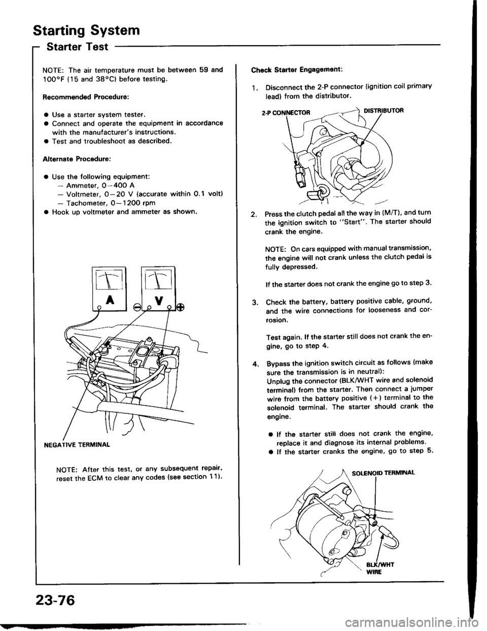
a Use the following equipment:- Ammeter. 0-4OO A- Voltmeter, O- 20 V {accurate within 0.1 volt)
- Tachometer, O- 120O rpm
a Hook up voltmeter and ammeter as shown'
NEGATIVE TERMINAL
NOTE: After this test, or any subsequent repair,
reset the ECM to clear any codes (see section 1 1)
23-76
2.
Chock Stan€r Engag6ment:
1. Disconnect the 2-P connector (ignition coil primary
lead) from the distributor.
Press the clutch pedal allthe way in (M/T), and turn
the ignition switch to "Start". The starter should
crank the engine.
NOTE: On cars equipped with manual transmission,
the engine will not crank unless the clutch pedal is
fully depressed.
lf the staner does not crank the engine go to step 3.
Check the baftery, battery positive cable, ground,
and the wire connections for looseness and cor-
rosion,
Test again. lf the starter still does not crank the en-
gine, go to step 4.
Bvpass the ignition switch citcuit as follows {make
sure the transmission is in neutral):
Unplug the connector (BLK/WHT wire and solenoid
terminsl) trom the starter. Then connect a jumper
wire from the battery positive ( + ) terminal to the
solenoid terminal. The starter should crank the
engrne.
a lf the starter still does not crank the engine,
replace it and diagnose its internal problems.
a lf the starter cranks the engine, go to step 5.
J.
4.
Page 1381 of 1413
Supplemental Restraint System (SRSI
Troubleshooting
Self-diagnosis Function
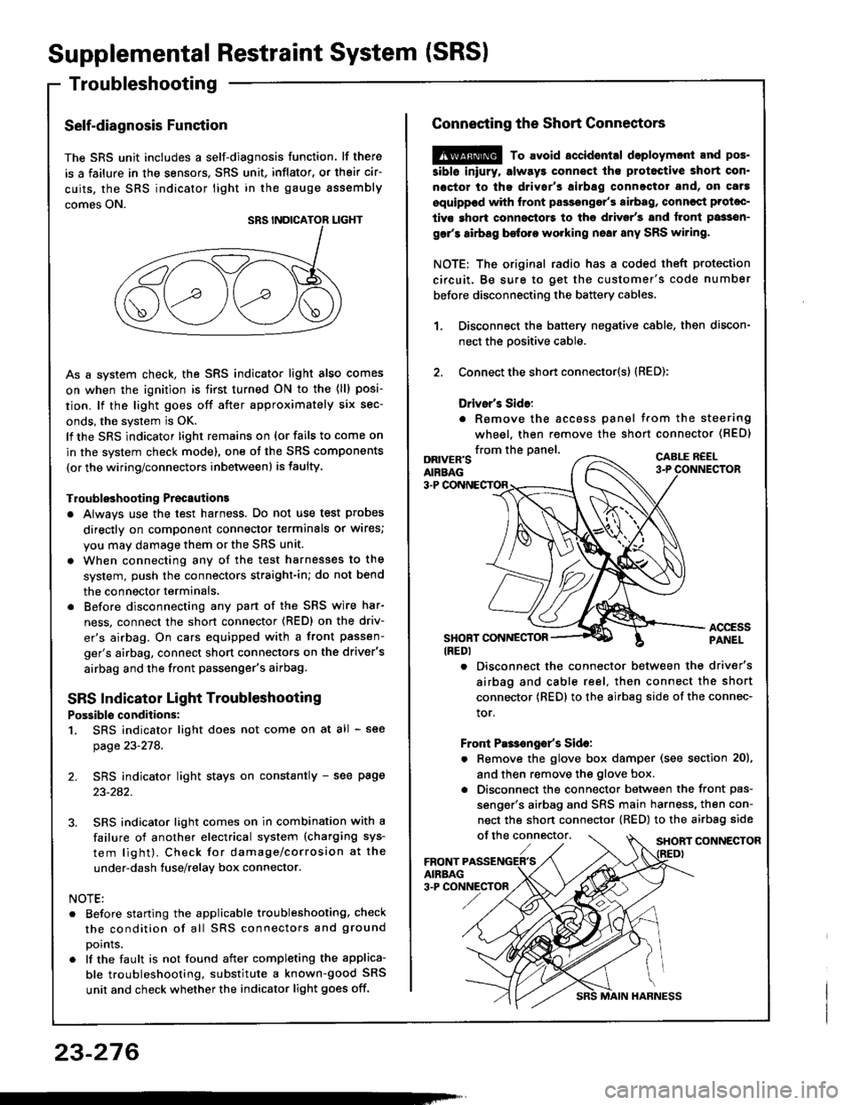
The SRS unit includes a self-diagnosis function. lf there
is a failure in the sensors. SRS unit, inflator, or their cir-
cuits, the SRS indicator light in the gauge sssembly
comes ON.
As a system check, the SRS indicator light also comes
on when the ignition is first turned ON to the (ll) posi-
tion. lf the light goes off after approximately six sec-
onds, the system is OK.
lf the SRS indicator lighr remains on (or fails to come on
in the system check mode), one of the SRS components
(or the wiring/connectors inbetween) is laulty
Troubleshooting Precautions
a Always use the test harness. Do not use test probes
directly on component connector terminals or wires;
you may damage them or the SRS unit.
a When connecting any of the test harnesses to the
system, push the connectors straight-in; do not bend
the connector terminals,
. Before disconnecting any part of the SRS wire har-
ness, connect the shon connector (RED) on the driv-
er's airbag. On cars equipped with a front passen-
ger's airbag, connect short connectors on the driver's
airbag and the front passenger's airbag.
SRS Indicator Light Troubleshooting
Possiblo conditions:
1. SRS indicator light does not come on at all - see
page 23-278.
2. SRS indicator light stays on constantly - see page
23-242.
3. SRS indicator light comes on in combination with a
failure of another electrical system (charging sys-
tem light). Check for damage/corrosion at the
under-dash tuse/relay box connector.
NOTE:
. Before starting the applicable troubleshooting. check
the condition of all SRS connectors and ground
points.
. lf the fault is not found after completing the applica-
ble troubleshooting, substitute a known-good SRS
unit and check whether the indicator light goes off.
23-276
MAIN HARNESS
Connecting the Short Connectors
@ To avoid.ccidental doploymont and pos.
siblo iniury. alway3 connect ths protoctive short con.
noctor to tha driver's airbag connectot and, on caf!
equippod with front passongor's airbag, conncqt Prolac-
tivs ghort connoctors to the d.ivsr's and tront passsn-
gar's airbag before working nsai any SRS wiring.
NOTE: The original radio has a coded theft protection
circuit. Be sure to get the customer's code number
before disconnecting the battery cables,
Disconnect the battery negative cable, then discon-
nect the oositive cable.
Connect the short connector(s) (RED):
Drivsr's Sido:
. Romove the accoss panel trom the steering
wheel, then remove the shon connector (BED)
1.
2.
from the panel.DRIVER'SAIRBAG
CABLE R€EL
3-P
ACCESSPANELSHONT CONNESTOR(REDI
. Disconnect the connector between the driver's
airbag and cable reel, then connect the short
connector {RED} to the airbag side of the connec-
tor.
Front Pas€ngo/s Sido:
. Remove the glove box damper (see section 20),
and then remove the glove box.
. Disconnect the connector between the front pas-
senger's airbag and SRS main harness, then con-
nect the short connector (RED) to the airbag side
of the connector,SHORT CONNECTOR
Page 1383 of 1413
Supplemental Restraint System (SRS)
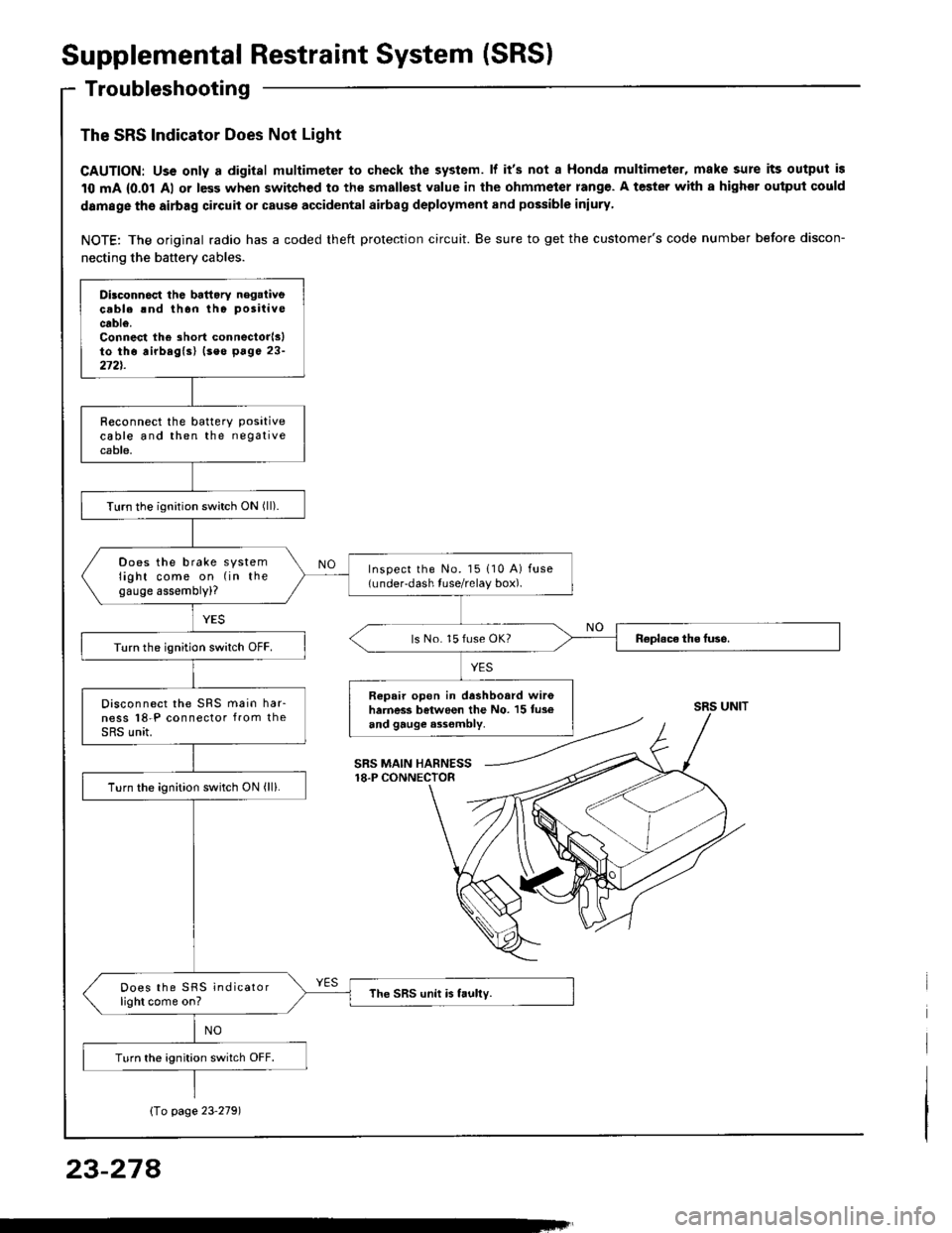
Troubleshooting
The SRS Indicator Does Not Light
CAUTION: Uss only a digital multimeter to check the system. lf it's not a Honda multimeter, make sure its output is
10 mA {0.01 Al or less when switched to the smallest value in the ohmmeter rang€. A tester with a highor ouiput could
damage the airbag circuit or cause accidental airbag deployment and possible iniury
NOTE: The original radio has a coded theft protection circuit. Be sure to get the customer's code number before discon-
necting the battery cables.
Dilconn6ct the battory negaiivecable rnd thon tho positive
cable.Connest the short connectorlslto tho airbaglsl (seo p6ge 23-272t.
R€connect the batterY Positivecable and then the negativecable.
Turn the ignition switch ON (ll).
Does the brake systemlight come on (in thegauge assembly)?
Inspect the No. l5 110 A) fuse(under-dash tuse/relay box).
ls No. 15 fuse OK?Turn the ignition switch OFF.
Repair open in dashboard wir6harness between the No. 15 tus€and gauge a3sombly.
Disconnect the SRS main har-ness l8-P connector from theSRS unit.
Turn the ignition switch ON (ll).
Does the SRS indicatorlight come on?The SRS unit is faully.
Turn the ignition switch OFF.
SRS UNIT
SRS MAIN HARNESS18.P CONNECTOR
Io page 23'2791
23-274
Page 1387 of 1413
Supplemental Restraint System (SRSI
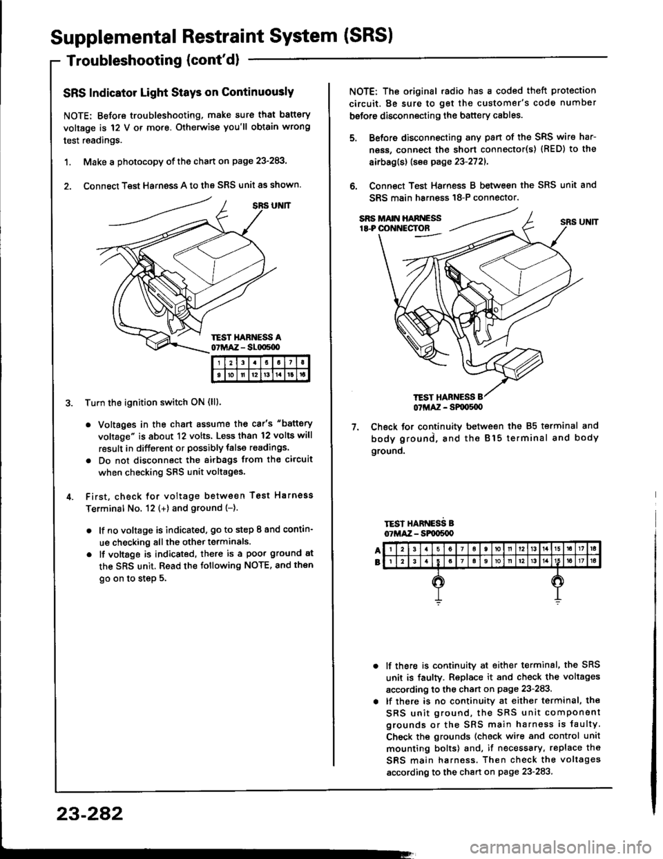
Troubleshooting (cont'dl
SRS Indicator Light Stays on Continuously
NOTE: Before troubleshooting, make sure that battery
voltage is 12 V or mo.e. Otherwise you'll obtain wrong
test readings.
1. Make a photocopy of the chart on page 23-283,
2. Connect Test Harness A to the SRS unit as shown.
Tu.n the ignition switch ON (lll.
. Voltages in the chart assume the car's "battery
voltage" is about 12 volts. Less than 12 volts will
result in different or possibly talse readings.
. Do not disconnect the airbags ftom the circuit
when checking SRS unit voltages.
First, check for voltage between Test Harnoss
Terminal No. 12 (+) and ground (-).
. lf no voltage is indicated, go to step I and contin-
ue checking all the other terminals.
o lf vottsge is indicated, there is a poor ground at
the SRS unit. Read the following NOTE, and then
go on to step 5.
I21I
tolll2t3tlrt
23-282
TEST HANNESS
NOTE: The original .adio has a coded theft protection
circuit. Be sure to get the customer's code number
before disconnecting the battery cables.
Before disconnecting any pan of the SRS wire har-
ness, connect the short connecto(s) {RED) to the
airbag(s) (see page 23-2721.
Connect Test Harness B between the SRS unit and
SRS main harn€ss 18-P connector.
7. Check for continuitv between the 85 terminal and
body ground, and the Bl5 terminal and body
ground.
TEST HARNESS B07MAZ - SPqrS{X)
lf there is continuity at either terminal, the SRS
unit is faulty. Replace it and check the voltages
according to the chan on page 23-283.
lf there is no continuity at either terminal, the
SRS unit ground, the SRS unit component
grounds or the SRS main harness is faulty
Check the grounds (check wire and control unit
mounting bolts) and, if necessary, replace th€
SRS main harness. Then check the voltages
according to the chart on page 23-283
Page 1389 of 1413
Supplemental Restraint System (SRSI
Troubleshooting (cont'd)
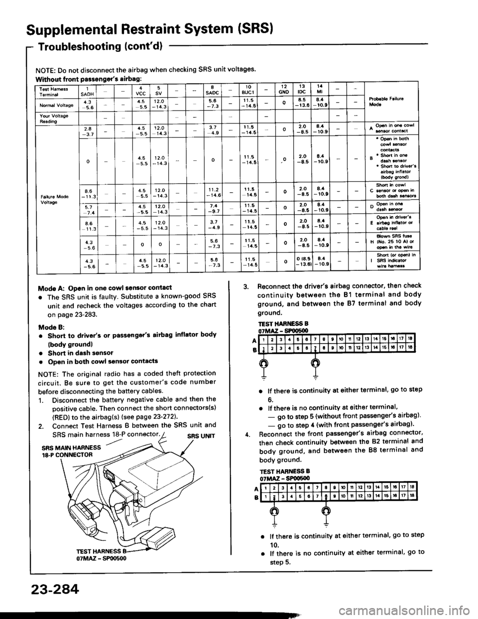
NOTE: Do not disconnect the airbag when checking SRS unit voltages.
Without lront Passongor's sirbag:
Modo A: Open in one cowl sonsor conlact
r The SRS unit is faultY. Substitute a known-good SRS
unit and recheck the voltages according to the chart
on page 23-283.
Mods B:
. Short to driver's or Passonger's aitbag inflator body
(body groundl
. Short in dash sonsor
. Opsn in both cowl sgnsor contacts
NOTE: The original radio has a coded theft protection
circuit. Be sure to get the customer's code number
before disconnecting the battery cables.
1. Disconnect the battery negative cable and then the
positive cable. Then connect the short connectots(s)
(RED) to the airbag(s) (see page 23-272).
2. Connect Test Harness B between the SRS unit and
A
B
SRS main harness 18-P connector.SRS UN]T'...SRS MAIN HARNESS18.P CONNECTOR
3. Reconnect the driv€r's airbag connector, then check
continuity between the B1 terminal and body
ground, and b€twesn the 87 terminsl and body
grounq,
TEST HABT{ESS B
. lf there is continuity at either terminal, go to step
o.
. lf there is no continuity at sither terminal'
- go to step 5 (without front passonge/s airbag)'
- go to step il (with front passenger's airbag)'
Reconnect the front passonger's sirbag connector,
then check continuity betwo€n ihs 82 t€rminal and
body ground, and between the 88 terminal and
body ground.
lf there is continuity at either terminal, go to step
10.
lf there is no continuity at either terminal, go to
step 5.
lSAOHvcc58saoc10BUCI12Gto13toct4
4,35.65.512.O- 14.35,6-7.311.5- 14,5oa_5-13.68.:aro.9
2.43.74.55.5
't2.o
14.33.74.911,5-14.5o2.O-8.58.4-r0.9
o4.55,512.O- 14.3o11.5-14,5o2.O-8.58./a-r0.9
4.6-11.3-5.512.O- 14.311.2- 14.611.514,5o2.O8./t-r0.9
5.74.5t2.o14,3-9.7tt.5- 14_5o-8.58.1-10.9
4.611.34.5- 5.512.0- 14.33.7-4.91t.514.5o2.O-8.5a.a-r0.9
4.3oo5,6-7.311.514,5o2,O8.it,r0.9H ll{o. 26 lo Al o.
4.3-5.64.5-5.512.O- 14.3-7.3t1.5- 14-5oo ta,5- 13.0tE,4-10.9
23-284