Page 1190 of 1413
BRUSHES
Starting System
Starter Field Winding Test
1. Check for continuity between the brushes. lf there's
no continuity, replace the armature housing.
2. Check for continuity between each brush and the ar-
mature housing {ground) lf continuity exists, replace
the armatule housing.
Overrunning Clutch InsPection
Slide the overrunning clutch slong the shatt.
Does it move treely? ll not, replace it.
Rotate the overrunning clutch both ways.
Does it lock in one direction and rotate smoothly in
reverse? lf it does not lock in either direction or it
locks in both directions, replace it.
DRIVE G€AR
ll the starter drive gear is worn or damaged, replsce
the ovsrrunning clutch assembly; the gea. is not
available separately.
Check the condition of the flywheel or torque con-
verter ring gear if the starter drive gear teeth ale
damaged.
4.
23-8,4
CLUTCH GEAR
Page 1196 of 1413
lgnition System
lgnition Timing lnspection and
Setting (cont'd)
5. To adjust ignition timing, loosen the distributor
mounting bolts, and turn the distributor housing
counterclockwise to advance the timing, or clock-
wise to retard the timing.
MOUNN G BOLTS24 N.m (2.4 kgl.m, 17 lbt'ftl
Tighten the adjusting bolts and recheck the timing.
Remove the SCS short connector trom the service
check connector.
2.
ldle Speed Inspection
Shift to neutral or Ll] and start the engine. Hold the
engine at 3,OOO rpm with no load until the radiator
fan comes on, then let it idle.
Connect a tachometer to the test tachometer con-
nector.
ldle sp6od
M/T: 750 t 50 rpm in neuttal
A/T: 75O t 50 rpm in @ or @
NOTE: Allelectrical systems should be turned OFF.
Adjust the idle speed il necessary (see section 1 1).
b.
23-90
Page 1211 of 1413
Alternator Overhaul
CAUTION: Do not r€move th€ pulley unl€Es the t.ontbearing needs r6placsm6nt.
To loosen the pulley locknut, use 10 mm and 22 mmwrenches. It necessary, use an impact wrench.
Test, page 23-107SPAC
REAR BEARING
ER RING
rl
@n
CAUTION: Do not get grease
or oil on the slip rings.
HOLDERTOR
ARUSH HOLOER
FRONT BEARING
PULLEY LOCKI{UT1'll N.m 111.3 kgt.m,82 tbf.trl
STATOR/DRIVE ENDHOUStt{G
BBUSHINSULA
)
(@P "
STATOR THROUGHBOLT
VOLTAGE REGULATOR
DIODE IRECTIFIER) ASSEMBLYTest, page 23-106
6
q
%A
re
TERMINAL INSULATORqt
PULLEY LOCKNUT111 N.m (1 1.3 kgt.m, 82 lbf.ft)
PULLEY
10 mm BOX WRENCH
REAR HOUSING
Inspection, page 23-
fu"- "o*n.r" ".,"- BRACKET
23-105
Page 1212 of 1413

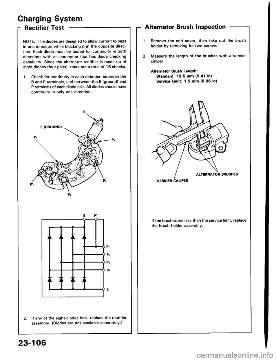
RectifierTest
NOTE: The diodes are designed to allow current to pass
in one direction while blocking it in the opposite direc-
lion. Each diode must be tested for continuitv in both
directions with an ohmmeter that has diode checking
capability. Since the alternator rectifier is made up of
eight diodes (four pairs), there are a total of '16 checks,
1. Check for continuity in each ditection between the
B and P terminals, and between the E (ground) and
P terminals of each diode pair. All diodes should have
continuity in only one direction,
lf any of the eight diodes tails, replace the rectifier
assembly. (Diodes are not available separately.)
Gharging System
Alternator Brush Inspection
Remove the end cover, then lake oul the brush
holder by removing its two screws
Measure the length of the brushes with a vernier
calioer.
Aliornatol Brush Longlh:
Standard: 10.5 mm (O.41 in)
Servic. Limit: 1.5 mm (O.06 in)
lf the brushes are less than the service limit, replace
the b.ush holder assemblv.
VERI{IEB CALIPEB
23-106
Page 1227 of 1413
{From previous page)
Check tor continuity between theBLK terminal and body ground.ls there battery voltage?
Measure voltage between theORN and the BLK wire terminals.Ropair opon belw€onVSS and ground G101.
Ropair opon in tho BLKrYEL wirobotwoen VSS and undor-dsshluse/rolay box.
ls there about 5 V?
Ropair op6n in th6 ORN wire orshon to body ground.Raise the tront of the car and sup-port it with salety stands.
Touch a probe to the ORN wireand connect at to body groundthrough a voltmeter.
Putthe car in neutralwith kev ON.
Slowly rotate one wheel with theother wheel blocked.
Does voltage pulse from O toabout 1O V?Roplac. tho VSS {see page23-1221.
Touch a probe to the ORN wireand connect it to body groundthrough a voltmeter.
Slowly rotate one wheelwith theother wheel blocked.
Ropair opon in th6 OBil wire bo-tween tho VSS and th6 3p.odo-molgt.
Ooes the meter indicatepulsing voltage?
23-121
Page 1237 of 1413

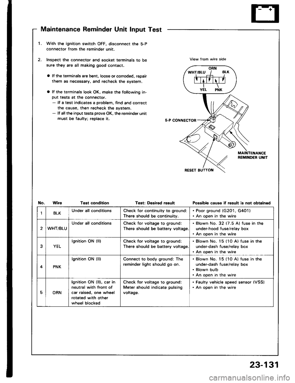
Maintenance Reminder Unit Input Test
1.With the ignition switch OFF, disconnect the 5-P
connector from the reminder unit,
Inspect the connector and socket terminals to be
sufe they are all making good contact.
a lJ the terminals are bent, loose orcorroded, repair
them as necessary, and recheck the svstem.
a It the terminals look OK, make the following in-
Put tests at the connecto..- lf a test indicates a problem, tind and correct
the cause, then recheck the system.- It allthe input tests prove OK, the reminder unit
must be taulty; replace it.
View trom wire side
No.WireTost condltionTest: DaEired rasultPossibl€ cause if result is not obtained
IBLKUnde. all conditionsCheck for continuity to ground:
There should be continuitv.
. Poor ground (G201, G4O1). An open in the wire
WHT/BLU
Under all conditionsCheck tor voltage to ground:
There should be battery voltage
. Blown No. 32 (7.5 A) fuse in the
under-hood tuse/relay box. An open in the wire
YEL
lgnition ON (lllCheck for voltage to ground:
There should be batte.y voltage
. Blown No. 15 (1O A) fuse in the
under-dash fuse/relay box. An open in the wire
4PNK
lgnition ON (ll)Connect to body ground; The
reminder light should go on.
Blown No. 15 (1O A) tuse in the
under-dash fuse/relay box
Blown bulb
An open in the wire
EORN
lgnition ON {ll), car in
neutral with lront ol
car raised, one wheel
rotated with other
wheel blocked
Check for voltage to g.ound:
Meter should indicate pulsing
voltage.
. Faulty vehicle speed sensor (VSS)
. An oDen in the wire
23-131
Page 1238 of 1413
A/T Gear PositionIndicator
Component Locationlndex
23-132
cAUTtOt{:
a All SRS olectdcal wiring harnossos a16 covarod with
yellow insulation.
Boforo disconnocting any part ot the SRS wlr. har-
noaa, conngct the short conn6ctor(sl.
Roplaco tho entire aff6ct6d SRS harn$s assombly il
it has an op6n cilcuit or damagod wiling,
SRS MAIN HARI{ESS(Cov.rod whh ygllow io.ul.tlonl
GAUGE ASSEMBLYBemoval, page 23-1 18Disassombly, pag€ 23'1 19Bulb Locations, pago 23-1 15IiIIERLOCK SYSTEMDGscription. page 23-139
A/T GEAR POSITIONIlTDICATORInput Test, pago 23-134
A/T GEAR P('SITIOI{ SWITCHTest, page 23-136ReDlacement, 6ection 14
Page 1239 of 1413
UNOER_HOOD FUSE / REI.AY 8OX
Circuit Diagram
IGNITIONswrTcHUNOER-OASHFUSSREI-AY 8OX
No.19ll0A)FUSE
TMI{SMrSSr0r,lc0IJTRori.IODULEITCMI
fitMritc-;-CANCEL lgll
tlYELTWHT GRN/8L|(
D4
II._l
TRANSMISSIONMODU|.! [TCM}
t
INTERLOCKcoMtRotUNJ]_
IGRT'IMHTo*nn,o_yTT
pr{x/cR1 -J
IGR €|-U -l
GRiITYEt
LT GNNiW{T
No.19 {lFUSE
V
I
I
DASH I-IGHTSBRIGHTNESSCONTROI.IERG2o lG401
I
G201G40t
/-?t ftrt*lwHT/BLX +wHT+ CH- Bl.x/Y€t -+<.\-o+!
y "l
IYEL
lln tho gtugo 8ls€mbvl
AN GEAR POSITION INDICATOR DIMMING CIRCUIT
A/T GEANPOStTt0NcoNsot-ELIGHT0.4w)
M GEARPosrTroN swncH
23-133