1994 HONDA INTEGRA engine
[x] Cancel search: enginePage 1126 of 1413
Connector ldentification and Wire Harness Routing
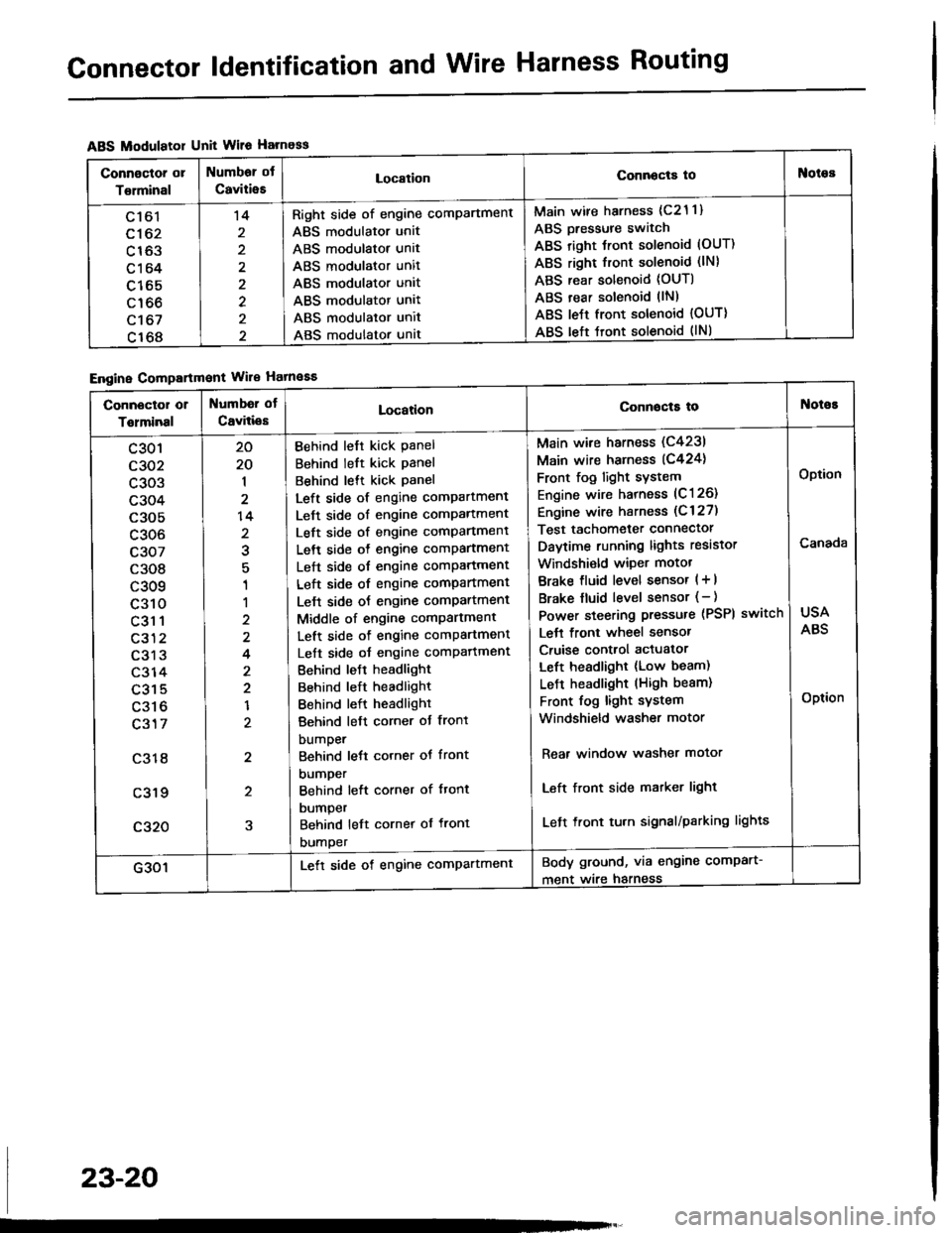
ABS Modulatol Unit Wile Harness
Engine Compartmont Wile Hatnaaa
Connoctor or
Torminal
Numbor ot
CaviiieELocationConnocta tooies
Ltol
c162
c163
c164
c165
c166
c't 67
c168
't4
2
2
Right side of engine comPartment
ABS modulator unit
ABS modulator unit
ABS modulator unit
ABS modulator unit
ABS modulator unit
ABS modulator unit
ABS modulator unat
Main wire harness (c21 1)
ABS Dressure switch
ABS right Jront solenoid (OUT)
ABS right front solenoid (lN)
ABS rear solenoid (OUT)
ABS rear solenoid llN)
ABS le{t front solenoid {OUT)
ABS left tront solenoid (lNl
Connector or
Tolminal
Numbd of
CaviliesLocationConnocta tot{oioE
c301
c302
c303
c304
c305
c306
c307
c308
c309
c310
c31 1
c312
c313
c314
c315
c316
c317
c318
c319
c320
20
20
1
2
14
2
1
1
2
4
2
2
1
2
2
5
Behind left kick Panel
Behind left kick panel
Behind lett kick Panel
Left side of engine compartment
Left side of engine comPartment
Left side of engine comPartment
Left side o{ engine comPartment
Left side of engine comPartment
Left side of engine compartment
Lelt side oJ engine comPartment
Middle of engine comPartment
Left side of engine comPartment
Left side oJ engine comPafiment
Behind leJt headlight
Behind left headlight
Behind left headlight
Behind left corner ot front
bumper
Behind lett corner ot front
DUmper
Behind left corner of ftont
DUmper
Behind left cornet of front
DUmper
Main wire harness (C4231
Main wire harness (C424)
Front fog light sYstem
Engine wire harness (C126)
Engine wire harness (C 127)
Test tachometer connector
Daytime running lights resistor
Windshi€ld wiper motot
Brake fluid level sensor ( + |
Brake fluid level sensor (- )
Power steering pressure (PSPI
Lett front wheel sensor
Cruise control actuator
Left headlight (Low beam)
LeJ-t headlight (High beam)
Front fog light system
Windshield washer motor
switch
Rear window washer motor
Left front side matker light
Left front tu.n signal/parking lights
USA
ABS
Option
Canada
Option
G301Lett side of engine comPartmentBody ground, via engine comPart-
ment wire harness
23-20
Page 1128 of 1413
Connector ldentification and Wire Harness Routing
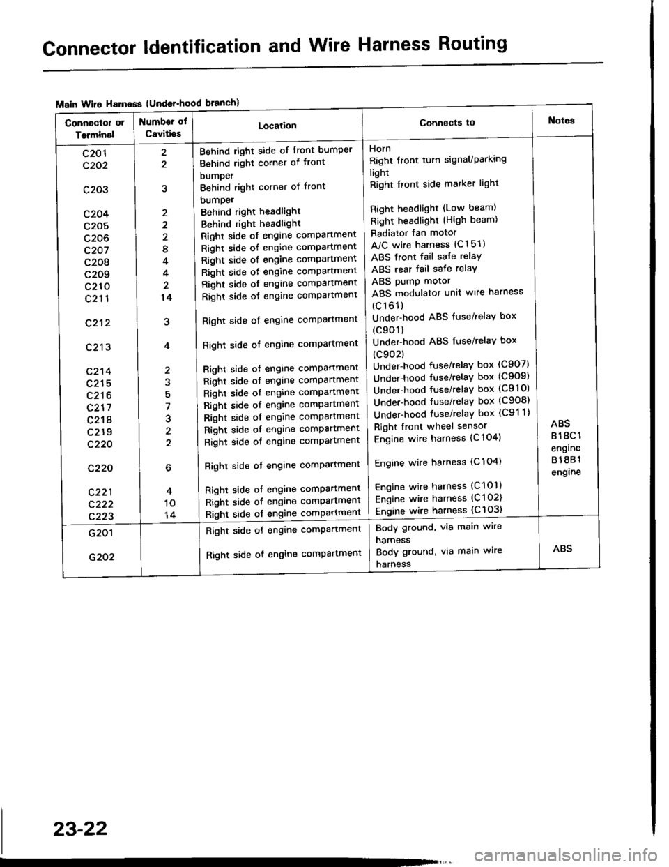
{Undor-hood
Horn
Right tront turn signal/Parking
light
Right Iront side marker light
Right headlight (Low beam)
Right headlight (High beam)
Radiator fan motor
A/C wire harness (C151)
ABS front fail saJe relay
ABS rear fail sate relay
ABS pump motor
ABS modulator unit wire harness
(c161)
Under-hood ABS fuse/relaY box
(c901)
Under-hood ABS fuse/relaY box
(c902)
Under-hood fuse/relay box (C907)
Under-hood tuse/relaY box (C909)
Under-hood fuse/relay box (C9l Ol
Under-hood fuse/relaY box (C908)
Under-hood fuse/relaY box (C91 1)
Right front wheel sensor
Engine wire harness {C 104)
Engine wire harness (C'l 04)
Engine wire harness (C101)
Engine wire harness (C l 02)
Engine wire harness {C 103)
Behind right side of tront bumper
Behind right corner of tront
bumper
Behind right corner of front
bumpet
Behind right headlight
Behind right headlight
Right side of engine comPartment
Right side of engine comPartment
Right side ot engine comPartment
Right side oJ engine comPartment
Right side of engine comPartment
Right side oJ engine comPartment
Right side of engine comPartment
Right side of engine comPartment
Bight side ot engine comPattment
Right side of engine comPartment
Right side of engine comPartment
Right side of engine comPartment
Right side of engine comPartment
Right side of engine comPartment
Right side of engine comPartment
Righl side ot engine comPartmenl
Right side of engine compartmenl
Right side of engine comPartmen'
Right side of engine comPartment
8
4
14
7
J
2
c201
c202
c203
c204
c205
c206
c207
c208
c209
c210
c211
c212
c213
c214
c215
c216
c217
c218
c219
c220
c220
c221
c222
c223
Body ground, via main wire
harness
Body ground, via main wire
harness
Right side of engine compartment
Right side of engine comPartment
23-22
Page 1130 of 1413
Connector ldentification and Wire Harness Routing
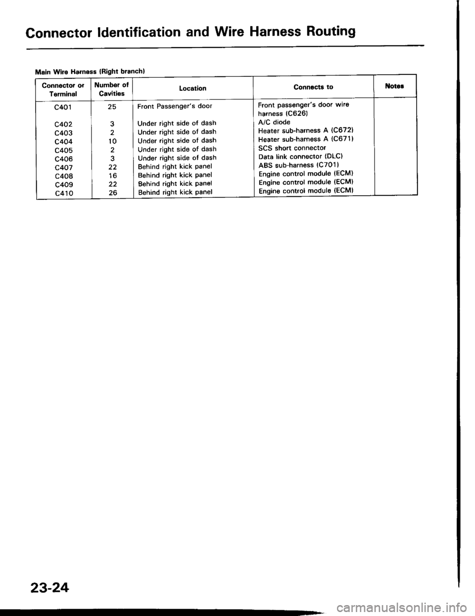
Main Wire Ha.ness {Right branch}
Connactor or
Terminal
Numbsr of
Caviti€sLocationConnscts tottlotor
c401
c402
c403
c404
c405
c406
c407
c408
c409
c410
,E
10
2
22
lo
22
26
Front Passenger's door
Under right side of dash
Under right side ot dash
Under right side of dash
Under right side of dash
Under right side ot dash
Behind right kick panel
Behind right kick panel
Behind right kick panel
Behind right kick panel
Front passenger's door wire
harness (C626)
A/C diode
Heater sub-harness A (C672)
Heater sub-harness A {C671}
SCS short connectol
Data link connector (DLC)
ABS sub-harness (C7011
Engine control module (ECM)
Engine control module (ECM)
Engine control module (ECMI
23-24
Page 1132 of 1413
Connector ldentification and Wire Harness Routing
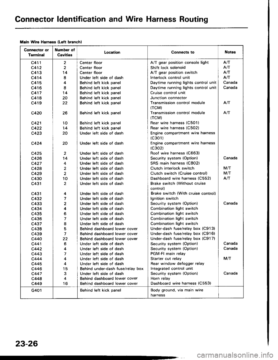
Msin Wiie Harness (Left branch)
Connector or
Terminal
Numbel ot
CavitiesLocationConnects toNotes
c411
c412
c413
c414
c415
c416
c4'17
c418
c419
c420
c42'l
c423
c424
c425
c426
c427
c42A
c429
c430
c431
c43l
c432
c433
c434
c435
c436
c437
c438
c439
c440
c44'l
c442
c443
c444
c445
c446
c447
c448
c449
26
10
20
20
14
8
4
I
14
20
22
't4
4
2
10
4
7
4
o
7
I
7
22
6
4
7
4
15
to
Center floor
Center floor
Center floor
Under left side ot dash
Behind left kick panel
Behind left kick panel
Behind left kick panel
Behind left kick panel
Behind left kick panel
Behind left kick panel
Behind left kick panel
Behind left kick panel
Under left side of dash
Under left side of dash
Under lett side of dash
Under left side ot dash
Under lett side of dash
Under lett side of dash
Under lett side of dash
Under lett side of dash
Under lett side ot dash
Under left side of dash
Under left side ol dash
Under left side of dash
Under left side of dash
Under left side of dash
Under left side of dash
Under left side of dash
Behind dashboard lower cover
Behind dashboard lower cover
Behind dashboard lower cover
Under left side of dash
Under left side of dash
Under left side of dash
Under lett side of dash
Under left side of dash
Behind under-dash fuse/relay box
Under left side ot dash
Behind dashboard lower cover
Behind dashboard lower cover
A/T gear position console light
Shift lock solenoid
A/T gear position switch
Interlock control unit
Daytime running lights control unit
Daytime running lights control unil
Cruise control unit
Junction connector
Transmission control module
(TCM)
Transmission controi module
{TCM)
Rear wire harness (C501)
Rear wire harness {C502)
Engine compartment wire harness
(c301)
Engine compartment wire harness
(c302)
Roof wire harness (C663)
Security system (Option)
SRS main harness (C802)
Clutch interlock switch
Clutch switch (Cruise control)
Dashboard wire harness (C552)
Brake switch (Without cruise
control)
Brake switch (With cruise control)
lgnition switch
Security system (Option)
Combination light switch
Combination light switch
Combination light switch
Combination light switch
Under-dash fuse/relay box {C9131
Under-dash fuse/relay box {C9161
Underdash tuse/relay box (C9'l 7l
Security system (Option)
Security system {Option)
PGM-FI main relay
Starter cut relay
Rear window defoqger relay
Integrated cont.ol unit
Security system {Option)
Horn relay
Dashboard wire harness (C553)
Afi
AiT
Afi
Afi
Canada
Canada
Arf
An
Canada
Canada
M/T
M/T
Atr
Canada
Canada
M/T
Canada
G401Behind left kick panelBody ground, via main wire
harness
23-26
Page 1150 of 1413
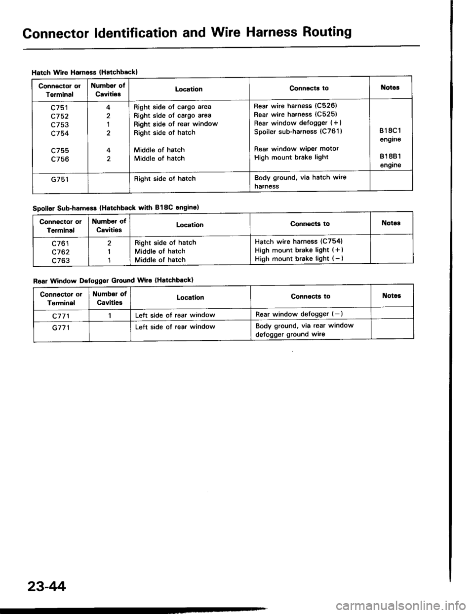
Connector ldentification and Wire Harness Routing
Hatch Wire Harnsss {Hatchbackl
Connector or
Torminal
Numbor ol
CaviliesLocationConnscts tol{otos
c751
c752
L/5J
c754
c755
4
1
4
Right side oJ cargo area
Right side of cargo area
Right side of reat window
Right side of hatch
Middle of hatch
Middle of hatch
Rear wire harness (C526)
Rear wire harness (C5251
Rear window defogger (+ I
Spoiler sub-harness (C761 )
Rear window wiper motot
High mount brake light
818C 1
engine
81 881
engine
G751Right side oJ hstchBody ground, via hatch wire
naaness
Spoilor Sub-harn6ss (Hatchback with B18C snginel
Roar Window Defoggor Ground Wire (Hatchbackl
Connoctor or
Terminal
Number ot
CavitiosLocalionConnocls toNotos
c761
c762
c763
I
1
Right side of hatch
Middle of hatch
Middle of hatch
Hatch wire harness (C754)
High mount btake light ( + )
High mount brake light ( - )
Connoctol or
Tgrminal
Numbor of
Caviti6sLocationConnoctg toNotes
c77'l1Lett side ot rear windowRear window defogger (-)
G771Left side ot rear windowBody ground, via tear window
deJogger ground wi.e
23-4r'i
Page 1155 of 1413
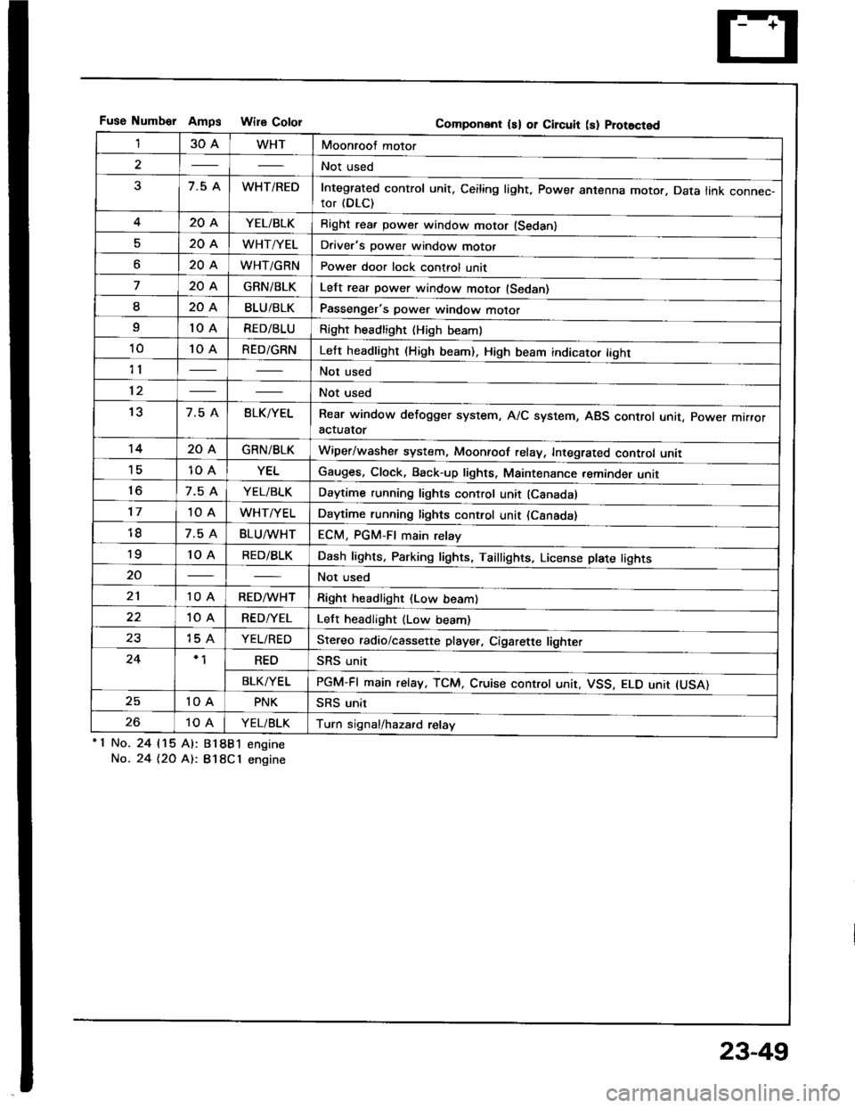
Fuse Numb€r AmDs Wire CololGomponent ls) or Circuit (s) Prot8cted
130AWHTMoonroof motor
2Not used
37.5 AWHT/REDIntegrated control unit, Ceiling light, Power antenna motor. Data link connec-tor (DLC)
420AYEL/BLKRight rea. power window motor (Sedan)
520AWHT/YELDriver's power window motor
o20AWHT/GRNPower door lock control unit
720AGRNiBLKLelt rear power window motor (Sedan)
I20ABLU/BLKPassenger's power window motor
I10 ARED/BLURight headlight {High beaml
1010 ARED/GRNLeft headlight (High beam). High beam indicato. tight
11Not used
12Not used
137.5 ABLK/YELRear window defogger system, A/C system, ABS control unit, power mrrroractuator
1420AGRN/BLKWiper/washer system, Moonroof relay, Integrated control unii'1510 AYELGauges, Clock, Back-up lights, Maintenance reminder unit
to7.5 AYEL/BLKDaytime running lights control unit (Canadal
1710 AWHT/YELDaytime running lights control unit (Csnada)
7.5 ABLU^tvHTECM, PGM-FI main relay'to10 ARED/BLKDash lights, Parking lights, Taillights, License plate tights
20Not used
2110 ARED/WHTRight headlight (Low beam)
10 ARED/YELLeft headlight (Low beam)
2315 AYEL/REDStereo radio/cassette player, Cigarette lighter
24REOSRS unit
BLK/YELPGM-FI main relay, TCM, Cruise controt unit, VSS, ELO unit IUSA)
2510 APNKSRS unit
2610 AYEL/BLKTurn signal/hazard relay'1 No.
No.
24 115 Al:
24 t2O At:.
81881 engine
B18Cl engine
23-49
Page 1182 of 1413
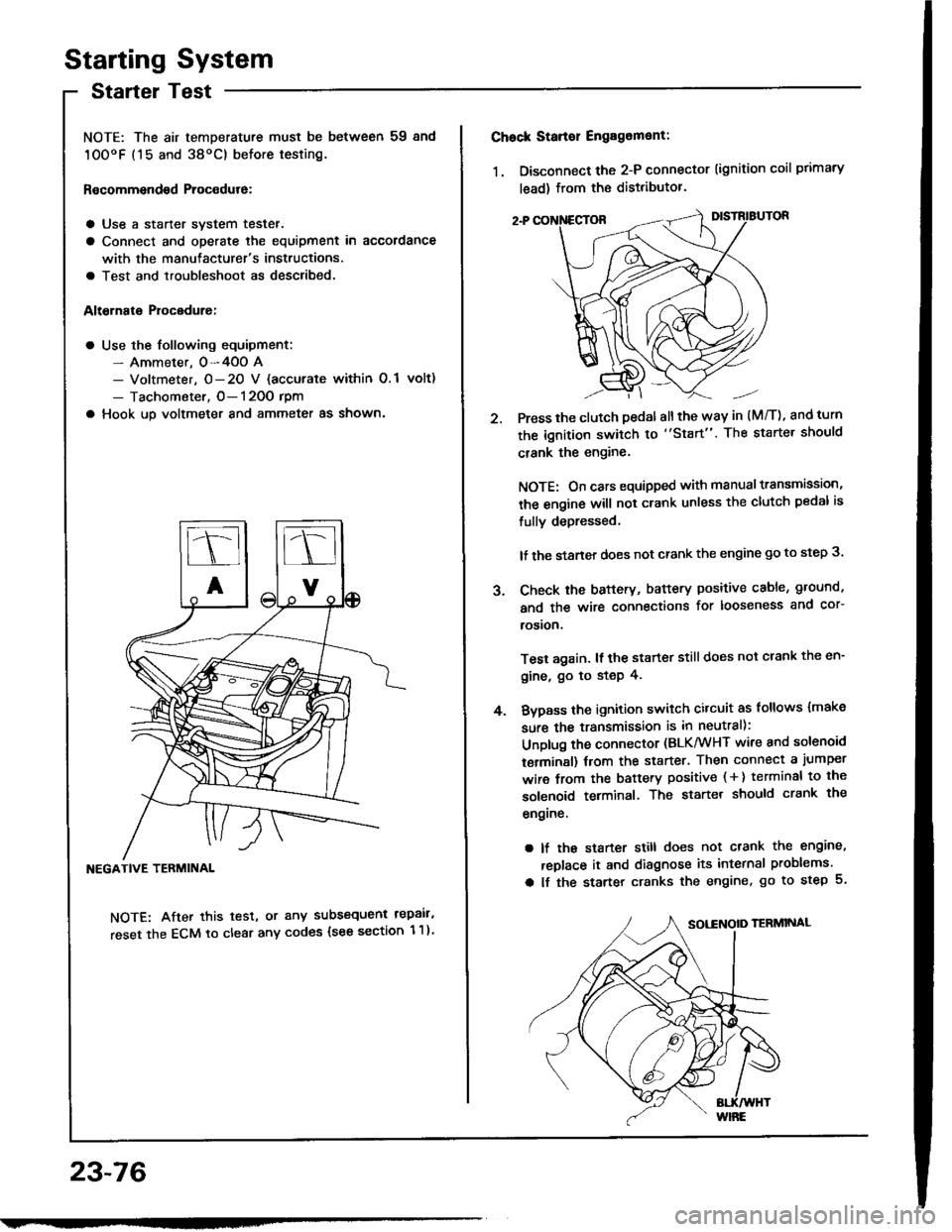
Starting System
Startel Test
NOTE: The air temDerature must be between 59 8nd
10OoF (15 and 38oC) before testing.
Recommendsd Procodure:
a Use a staner svstem tester.
a Connect and operate the equipment in accordance
with the manutacturer's instructions.
a Test and troubleshoot as described.
Altohato Procedure:
a Use the following equipment:- Ammeter. 0-4OO A- Voltmeter, O- 20 V {accurate within 0.1 volt)
- Tachometer, O- 120O rpm
a Hook up voltmeter and ammeter as shown'
NEGATIVE TERMINAL
NOTE: After this test, or any subsequent repair,
reset the ECM to clear any codes (see section 1 1)
23-76
2.
Chock Stan€r Engag6ment:
1. Disconnect the 2-P connector (ignition coil primary
lead) from the distributor.
Press the clutch pedal allthe way in (M/T), and turn
the ignition switch to "Start". The starter should
crank the engine.
NOTE: On cars equipped with manual transmission,
the engine will not crank unless the clutch pedal is
fully depressed.
lf the staner does not crank the engine go to step 3.
Check the baftery, battery positive cable, ground,
and the wire connections for looseness and cor-
rosion,
Test again. lf the starter still does not crank the en-
gine, go to step 4.
Bvpass the ignition switch citcuit as follows {make
sure the transmission is in neutral):
Unplug the connector (BLK/WHT wire and solenoid
terminsl) trom the starter. Then connect a jumper
wire from the battery positive ( + ) terminal to the
solenoid terminal. The starter should crank the
engrne.
a lf the starter still does not crank the engine,
replace it and diagnose its internal problems.
a lf the starter cranks the engine, go to step 5.
J.
4.
Page 1183 of 1413
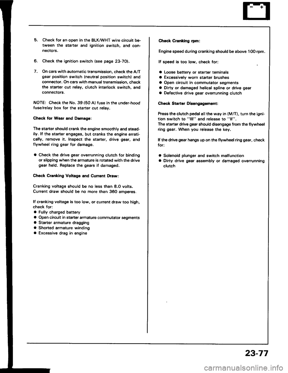
5. Check lor 8n op€n in the BLKMHT wire circuit be-
tween the staner and ignition switch, and con-
nectors.
6. Check the ignition switch (see page 23-70).
7, On cars with automatic transmission, check the A/Tgear position switch (neutral position switchl and
connector. On cars with manualtransmission, check
the staner cut relay, clutch interlock switch, and
connectors.
NOTE: Check the No. 39 (5O A) fuse in the under-hood
fuse/relay box for the starter cut relay.
Check tor Woar and Damago:
The starter should crank the engine smoothly and stead-
ily. lf th€ startsr engages, but cranks the engine errati-
cally, remove it. Inspect the starter, drive gear, and
flywheel ring gesr for damage.
a Check the drive gear overunning clutch for binding
or slipping when the armature is rotated with the drivegear held. Replace the gesrs if damaged.
Check Cranking Voltago 8nd Current Draw:
Cranking voltage should be no less than 8.O volts.
Current draw should be no more than 360 amperes.
lf cranking voltag€ is too low, or current draw too high,
check for:
a Fully charged battery
a Open circuit in starter armature commutatot segments
a Starter armature dragging
a Shoned armature winding
a Excessive drag in engine
Chack Cranking rpm:
Engine spsod during cranking should be above 1O0 rpm.
lf spe6d is too low, ch€ck for:
a Loose battsry or starter teminals
a Excessively worn starter brushes
a Open circuit in commutator segments
a Dirty or damaged helical spline or drive gear
a Defective drive gear overrunning clutch
Chock StErtor Disongagomoni:
Press the clutch pedal allth€ way in (M/T), turn the ioni-
tion switch to "lll" and rolease to "11".
The starter drive gear should disengage from the tlywheel
ring gear. When you rolease the key.
lf the drive gear hangs up on th€ flywheel ring gear, check
for:
a Solenoid plunger and switch malfunction
a Dirty drive gear assembly or damaged overrunning
clutch
23-77