1994 HONDA INTEGRA engine
[x] Cancel search: enginePage 1045 of 1413
Troubleshooting
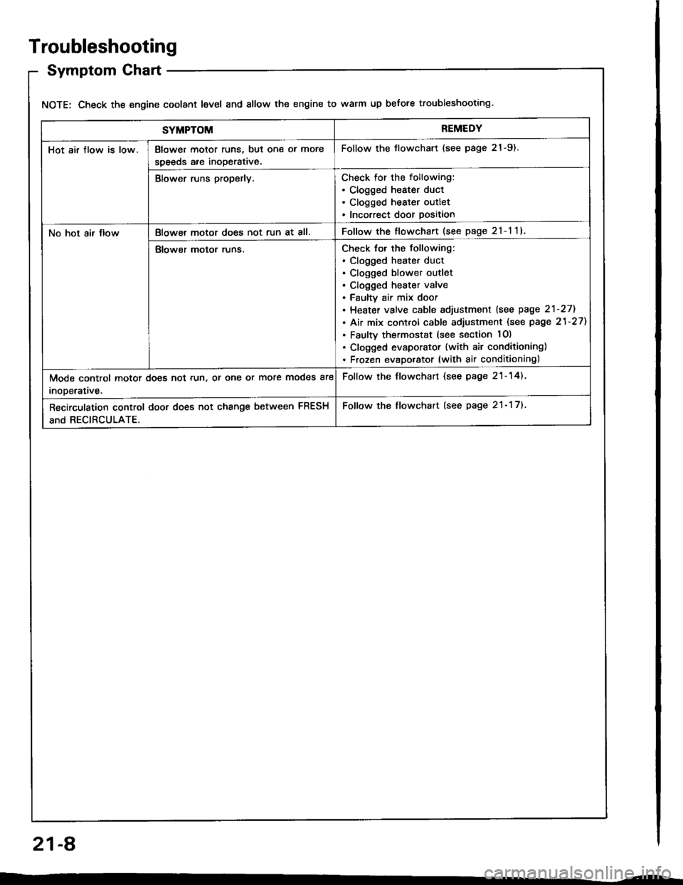
Symptom Chart
NOTE: Check the engine coolant level and allow the engine to warm up before troubleshooting.
SYMPTOMREMEDY
Hot air flow is low.Blower motor runs, but one ol more
speeds are inoperative.
Follow the tlowchart (see page 21-9).
Blower runs properly.Check for the following:. Clogged heater duct. Clogged heater outlet. Incorrect door position
No hot air JlowBlowel motor does not run at all.Follow the flowchart (see page 2l-l1l
Blower motor runs.Check for the following:. clogged heatet duct. Clogged blower outlet. Clogged heater valve. Faultv air mix door. Heater valve cable sdjustment lsee page 2'l-271
. Air mix control cable adjustment (see page 21-27)
. Faulty thermostat (see section lO)
. Clogged evaporator (with air conditioning). Frozen evaporator (with air conditioning)
Mode control motor does not run, or one or more modes are
inooerative.
Follow the flowchart (see page 21-14).
Recirculation control door does not change between FRESH
and RECIRCULATE.
Follow the flowchart (see page 21- 17).
21-A
Page 1059 of 1413
Heater Unit
Replacement
CAUTION:
a All SRS electrical witing hame$os are covoed wlth
yollow insulation.
a Before disconnecting any patt of tho SRS wito har-
neas, connect tha shott connoctol(s|.
a Roplaco th€ enlire sffacted SRS harnosr a$smbly if
it has an opon cilcult or dsmaged wiring.
NOTE: The original radio h8s a coded theft protection
circuit. Be sure to get the customer's code number betors
- disconnecting the bafterY.
- removing the No. 32 (7.5 A) fuse from th€ under-
hood tuse/relav box.- removing the radio
After service. teconnect power to the radio and turn it
on, when the word "CODE" is displayed, enter the cus-
tomer's 5-digit code to restore radio operation.
1. When the engine is cool, dtain the engine coolant
from the radiator (see section 1O).
@@ oo not lomove tho radiator cap whan
the ongine is hol; tha ongino coolant is undot
pressure and could a€voralY tcald you.
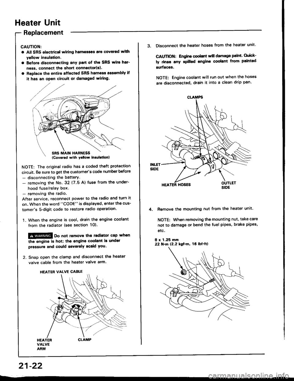
2. Snap open the clamp and disconnect the heater
valve cable from the heater valve arm.
HEATER VALVE CABLE
21-22
CLAMFS
3. Disconnect the heater hoses from the heater unit'
CAUTIOII: Engino coobnt will damago paint. orick-
ly dnse any rpilled engine coolant from paintod
surfac63.
NOTE: Engine coolant will tun out when the hoses
are disconnected, drain it into a clean drip pan'
HEATER HOSES
Remove the mounting nut from the heater unit.
NOTE: When removing the mounting nut, take care
not to damage or bend the fuel pipes, brake pipes,
etc.
8 r 1,25 rn|n22 N.m 12.2 kgt.m, tO lbf'ftl
4.
Page 1060 of 1413
5.
6.
7.
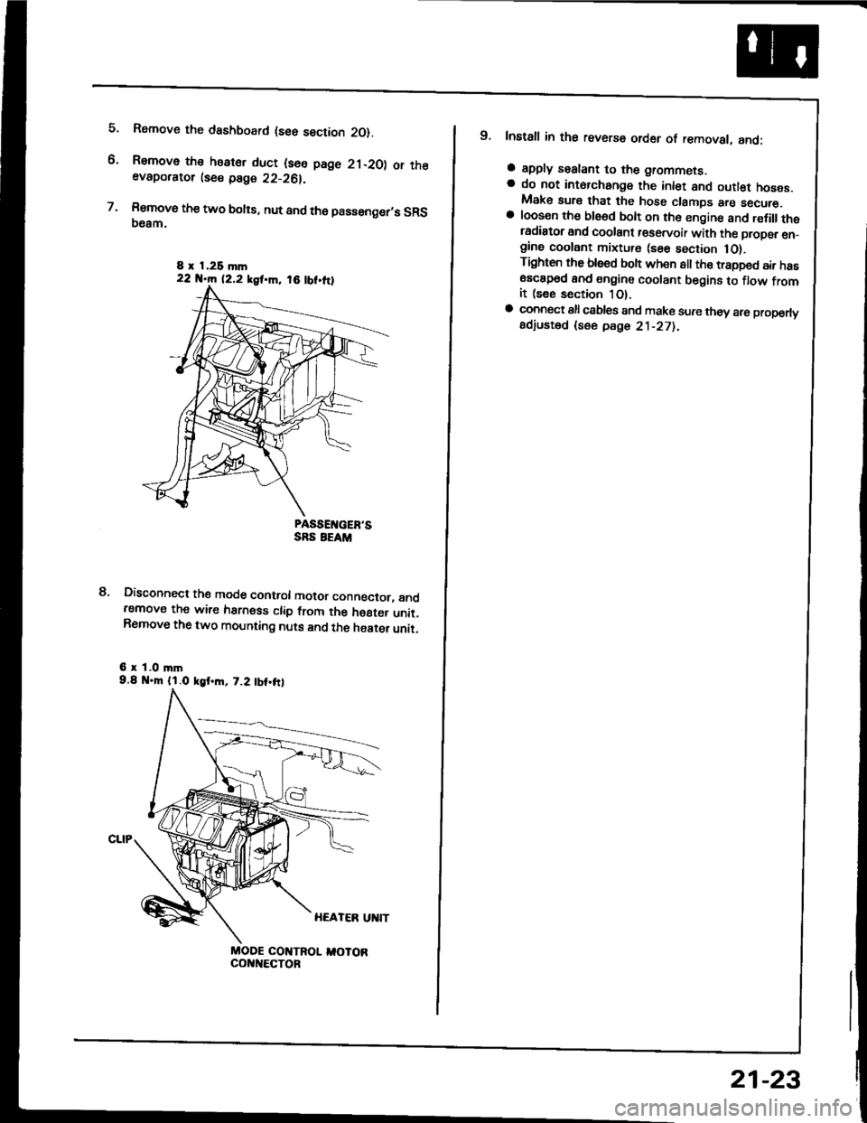
Rsmove the dashboard (see section 2O).
Remove the heater duct (see page 21-20) or theevaporator lse€ page 22-26).
Rsmove the two bolts, nut and the passenger,s SRS(}eam.
PASSEIVGER'SSRS EEAM
Disconnect the mode control motor conngctor, andremove the wire harness clip from the h€8ter unit.Remove the two mounting nuts and the haater unit.
6 r 1.0 mm9.8 .m (l.O kgt.m, 7.2 tbt.frl
MODE COI{TROL I,IOTORcol{t{€cToF
8.
8 x 1,26 mln22 N.m 12.2 kgf.m, 18 tbt.ttl
9. Install in the reverse order of removal, and:
a apply sealant to the grommets.a do not int6rchange the inlet and outl€t hoses.Make sure that the hose clamps are secure.a loosen th€ ble6d bolt on th6 engine and r€fillthetadiator and coolant r€servoir with the propsr en_gine coolant mixture (sse section 1O).Tighten the blsed boh when all the trapped air has6sc8p6d and engine coolant begins to flow fromit (see section 1O).a connect all csbles and make sure they 8re properlyadiusted (see pdge 21-271.
21-23
Page 1075 of 1413
Troubleshooting
Reference Ghart
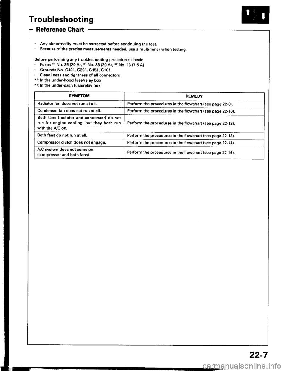
. Any abnormality must be correctsd before continuing the test.. Because of the precise measurgments needed, use a multimeter when testing.
Before performing any troubleshooting procedures check:. Fus€s .r No. 35120 A), *1 No. 33 (20 A), ), No. 13(7.5A). Grounds No. G401, G201, G'151, G101. Cleanliness and tightness of all connectors*1: In the under-hood fuse/relay box*2: In the under-dash fuse/relay box
SYMPTOMREMEDY
Radiator fan does not run 8t all.Perform the procedures in the flowchan (see page 22-8).
Condenser fan does not run at all.Perform the procedures in the flowchart (see page 22-10).
Both fans (radiator and condenser) do not
run for engine cooling, but they both run
with the Ay'C on.
Perform the procedures in the flowchan (see page 22-12).
Eoth fans do not run at all.Perform the procedures in the flowchart (see page 22-13).
Compressor clutch does not engage.Perform the procedures in the flowchart (see page 22-14).
Ay'C system does not come on
{compressor and both fans}.Perform the procedures in the flowchart (see page 22-16).
22-7
Page 1092 of 1413
A/G System Service
Performance Test
The performance test will help determine if the air con-
ditioner system is operating within specitications.
Only use service equipment that is U.L.-listed and is cer-
tified to meet the requirements of SAE J2210 to remove
HFC-134a {R-134a) from the air conditioner system.
CAUTION: Exposure to air conditioner relrig€rant and
lubricant vapor ot mist can irritate eyes, nose and
throat. Avoid breathing the air conditioner rstrigerant
and lubricant vapor or mi3t.
It accidental system discharge occurs, ventilate work
area before resuming service.
R-134a service equipment or vehicle air conditioner sys-
tems should not be pressure tested or leak tested with
comPressed atr.
!@ some mixtures ot air and R'1344 hrv6
been shown to be combustibls at elovatod prsssurel
and can result in firg or explosion causing iniury 01
property damage. Ngvor usg compregsed ail to prossuro
t€st R-134a ssrvice equipment or vohicl€ air conditioner
syst€ms.
Additional health and safety information may be
obtained from the refrigerant and lubricant manufactur-
ers.
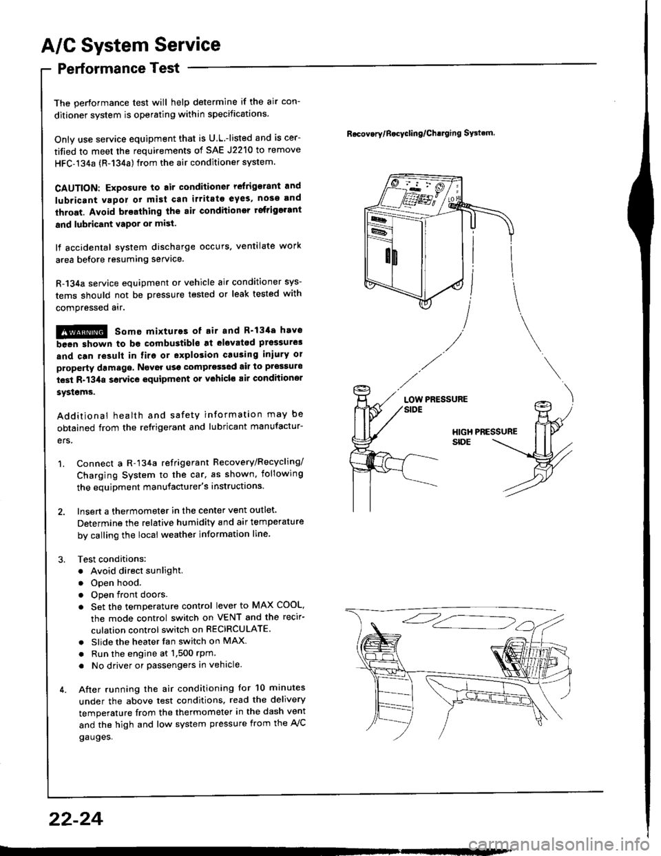
1. Connect a R-134a refrigerant Recovery/Recycling/
Charging System to the car, as shown, iollowing
the equipment manufacturer's instructions.
2. Insert a thermometer in the center vent outlet.
Determine the relative humidity and air temperature
by calling the local weather information line,
3. Test conditions:
. Avoid direct sunlight.
. Open hood.
. Open front doors
. Set the temperature control lever to MAX COOL,
the mode control switch on VENT and the recir-
culation control switch on RECIRCULATE.
. Slide the heater fan switch on MAX
. Run the engine at 1,500 rPm
. No driver or passengers in vehicle.
4. After running the air conditioning for 10 minutes
under the above test conditions. read the delivery
temperature from the thermometer in the dash vent
and the high and low system pressure from the A,/C
gauges.
Rocov.rylB.cycling/Ch!lging SFtrm.
PRESSURELOW
22-24
Page 1101 of 1413
A/C Compressor Belt
Replacement
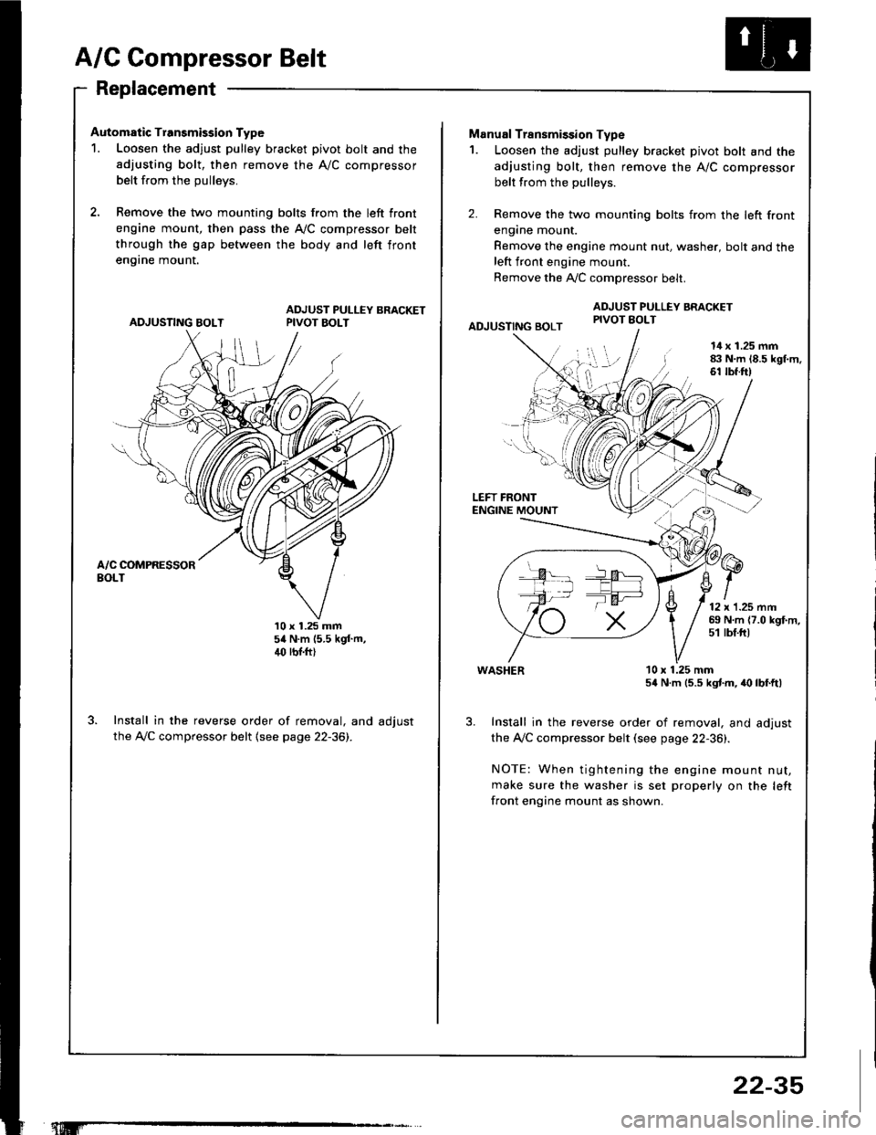
Automatic Transmission Type
1. Loosen the adjust pulley bracket pivot bolt and the
adjusting bolt, then remove the A/C compressor
belt from the oullevs.
2, Remove the two mounting bolts from the left front
engine mount, then pass the A,/C compressor belt
through the gap between the body and left front
en9rne mount.
ADJUSTING BOLTADJUST PULLEY BRACKETPIVOT BOLT
10 x 1.25 mm54 N.m (5.5 kgf.m,4(' rbr.ft)
Install in the reverse order of removal, and adjust
the A,/C compressor belt (see page 22-36).
"t.M'
22-35
-la ar-
Manual Transmission Type
1. Loosen the adjust pulley bracket pivot bolt and the
adjusting bolt, then remove the A/C compressor
belt from the pullevs.
2. Remove the two mounting bolts from the left front
engane mount.
Remove the engine mount nut, washer, bolt and theleft front engine mount.
Remove the A,./C comoressor belt.
ADJUSTING BOLT
ADJUST PULLEY BRACKETPIVOT EOLT
l!l',
I
14 x 1.25 mm83 N.m 18.5 kgl.m.61 tbf.ft)
LEFT FRONTENGINE MOUNT
12 x'1.25 mm69 N.m {7.0 kgf.m,51 tbf.ftt
WASHER
Install in the reverse order of removal, and adjust
the Ay'C compressor belt (see page 22-36).
NOTE: When tightening the engine mount nut,
make sure the washer is set properly on the left
front engine mount as shown.
10 x 1.25 mm54 N.m (5.5 kgtm, irc lbf.ft)
Page 1102 of 1413
A/C Compressor Belt
Adjustment
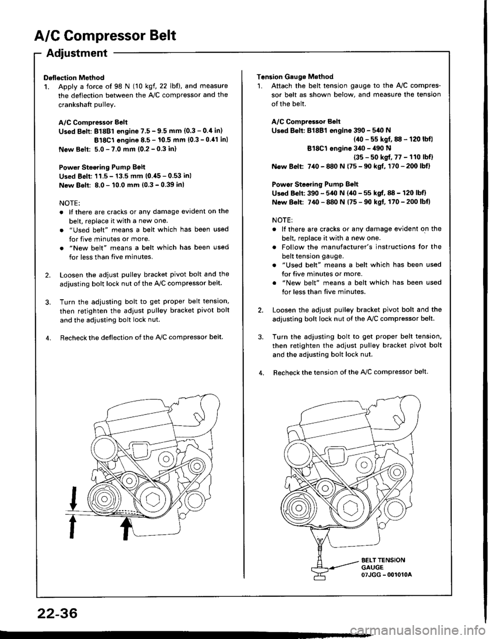
Dstlsqtion Method
1. Apply a force of 98 N (10 kgf, 22 lbf), and measure
the deflection between the A,/C compressor and the
crankshaft Dullev.
A/C Compressor Belt
Us€d Eelt: 81881 engine 7.5 - 9.5 mm (0.3 - 0.4 in)
Bl8Cl engine 8.5 - 10.5 mm (0.3 -0.11 inl
New Belt: 5.0 - 7.0 mm (0.2 - 0.3 inl
Power Stesring Pump Belt
Used Beli: 'l1.5 - 13.5 mm (0.,[5 - 0.53 inl
New 8€lt: 8.0 - 10.0 mm (0 3 - 0.39 inl
NOTE:
. lf there are cracks or any damage evident on the
belt, replace it with a new one.
. "Used belt" means a belt which has been used
for five minutes or more.
. "New belt" means a belt which has been used
for less than five minutes.
2. Loosen the adjust pulley bracket pivot bolt and the
adjusting bolt lock nut of the Ay'C compressor belt.
3. Turn the adiusting bolt to get proper belt tension,
then retighten the adjust pulley bracket pivot bolt
and the adjusting bolt lock nut.
4. Recheck the deflection of the lvc compressor belt
22-36
Tonsion Gauge Method
1. Attach the belt tension gauge to the Ay'C compres-
sor belt as shown below, and measure the tension
of the belt.
A/C Compressot Belt
Used 8€lt: Bl8Bl engine 390 - 540 N
(40 - s5 kgf, 88 - 120 lbfl
Bl8Cl ongine 3il0 - il90 N
(35 - s0 kgf, 77 - 110 lbfl
N€w Belt 7,10 - 880 N {75 - 90 kgf, 170-200lbl}
Powor Steoring Pump Belt
Used Belt: 390 - 5,{l N (40 - 55 kgf, 88 - 120 lbll
N6w Bolt: 74O - 880 N 175 - 90 kgf, 170-200lbt)
NOTE:
. lf there are cracks or any damage evident on the
belt, replace it with a new one.
. Follow the manufacturer's instructions for the
belt tension gauge.
. "Used belt" means a belt which has been used
for five minutes or more.
. "New belt" means a belt which has been used
tor less than five minutes,
2. Loosen the adjust pulley bracket pivot bolt and the
adjusting bolt lock nut of the AVC compressor belt.
3, Turn the adjusting bolt to get proper belt tension,
then retighten the adjust pulley bracket pivot bolt
and the adjusting bolt lock nut.
4. Recheck the tension of the A{/C compressor belt.
Page 1107 of 1413

Electrical
Special Tools
Troubleshooting
Tips and Precautions ................................ 23-3Five-stop Tloubleshooting ..............,...-..-... Z3-sSchematic Symbols ................................_. 23-6wire Color Cod€s ..................................... 23-6Relay and Control Unit Locations
Engine Compartment .........,............ ... --. 23-7Dsshboard and Door ..,,......................... 23-gDashboard and Floor ............................. 23-t OOuaner Panel .....-.....23-12Connector ldentification and WireHarness Routing ........ 23-i 3
Index to Circuits and Systems
Airbag ............... ...-..-... 2g-26sAir Conditioning ....,.. Section 2lAltelnator ......_.............. 23-99Anti-lock Brake Systsm (ABS) Section 19Automatic Transmission Section 14Battery .............. .......... 23-66Chafging System ........... 23-98rCigalstte Lighter .....................-...-......-..-.. Z3-2O4Cfock ................. ..........23-197rcruise Controf .......--..-... 23-242Distributor .................... 23-87Fan Controls ................. 23-1ogFuel and Emissions ... Section 1i*Fuses
Under-dash Fuse/Relay Box ................... 23-48Undor-hood ABS Fuse/Retay Box ............ 23-51Under-hood Fuse/Relay Box,.................. 23-52rGauges
Engine Coolant Temperature {ECT)Gauge ................ ..23-126Fuef cauge ............... 2g-123'Gauge Assembly ....--.23-113Speedometer .....-...,,. 23-114Tachometer .....,.....-.. 23-114Ground Distribution ........ 23-60Heater ,,,........,.... ..... Section 2lrHorn ................. ........... 23-199*fgnition Switch ............. 23-70fgnition Syst6m .......-..-.. 23-A7lgnition Timing .............. 23-89Indicator Lights"A/T Gear Position .............. ................... 23-1 32B1ak6 System ...,..,..-.23-127Engine Oil Pressura .............................. _ 23-1 51Low Fuel ............ ......23-125Malfunction Indicator Lamp {MlL} ...,,. Section I l
tfnteglated Control Unit ...29-144*lnterlock System ...................................... 23-1 3gLights, Exteriol
Back-up Lights ........... 23-179Brake Lights .............. 23-t8ltDaytime Running Lights {Csnada} ........... 23-156Front Palking Lights ............................. 23-1 65Flont Side Marker Lights ....................... 23-165Front Turn Signal Lights ........................ 23-1 65*Hazard Warning Lights .........................- 2g-1A4Headlights ................. 23-t6tLicense Plate Lights .............................. 23-1 69Taillights(Harchback) .......... 23-166
{Sedan) .............. .. 23-167Lights. Inteliol
Cargo Area Light {Hatchback) ...... -.. -.. -... 23-177Ceifing Light ........-..-.23-175
Dash Lights Blightness Controt .............. 23-t70Glove Box Lighr ................................... 23-1 69Spotfighr ............ ....-.23-174Trunk Light (Sedanl ............... .............. - 23.-177*Lighting Sysrem .......-.-... 23-152:Moonroof ,,.,.......,..,,,,,.-.23-211PGM-FI Systom ........ S€crion 11Power Distribution .,.-..--..23-54Power Door Locks .............,,..................... 23-233Power Mirors ..,..,....-...- 23-216Power Relays ...........,..... 23-68Power Windows ............ 29-222*Rear Window Defogger ........,... ..........,..... - 23-20,6Reminder Systems
Key-in Remindel System ....,.............,.... 23-1 50Lights-on Reminder System ................... 23-l 5f*Maintenance Reminder system ..,,.... -.. - -. 23-.1 2gSeat Belt Reminder System ..................- 23-125*Side Markel/Turn Signal/Hazard
Ffasher System .,..,..-.23.-1A4Spark Pfugs .........-...-..... 23-97Starting System ....,,.....-. 23-73*Stereo Sound System ...,.......................,,.. 23-l gg
Supplemental Restraint System {SRS} ......... 23-265Vehicfe Speed Sensor {VSS) .............--..-.... 23-122*Wiper/Washer Systom ...............--.........-..- Zg-254
rRead SRS pi€cautions on Page 23-271 betore workingin these areas.
-+