Page 1075 of 1413

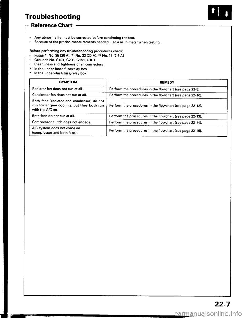
Troubleshooting
Reference Ghart
. Any abnormality must be correctsd before continuing the test.. Because of the precise measurgments needed, use a multimeter when testing.
Before performing any troubleshooting procedures check:. Fus€s .r No. 35120 A), *1 No. 33 (20 A), ), No. 13(7.5A). Grounds No. G401, G201, G'151, G101. Cleanliness and tightness of all connectors*1: In the under-hood fuse/relay box*2: In the under-dash fuse/relay box
SYMPTOMREMEDY
Radiator fan does not run 8t all.Perform the procedures in the flowchan (see page 22-8).
Condenser fan does not run at all.Perform the procedures in the flowchart (see page 22-10).
Both fans (radiator and condenser) do not
run for engine cooling, but they both run
with the Ay'C on.
Perform the procedures in the flowchan (see page 22-12).
Eoth fans do not run at all.Perform the procedures in the flowchart (see page 22-13).
Compressor clutch does not engage.Perform the procedures in the flowchart (see page 22-14).
Ay'C system does not come on
{compressor and both fans}.Perform the procedures in the flowchart (see page 22-16).
22-7
Page 1198 of 1413
lgnition System
Distributor Installation
Coat a new O-ring with engine oil, then install it.
Slip the distributor into position.
NOTE: The lugs on the end of the distributor and
its mating grooves in the camshaft end are both off-
set to eliminate the possibility ot installing the dis-
tributor 18Oo out of time.
DISTRIBUTOR END CAMSHAFT END
Install the mounting bolts and tighten them tem-
porarily.
Connect the 2-P and 8-P connectors to the dis-
tributor.
24 N.m (2.4 kgf'm' 17 lbt'ft|
23-92
5. Connect the ignition wires as shown.
Set the timing with a timing light (se€ page 23-89).
After setting the timing, tighten the mounting bolts.
Page 1240 of 1413
A/T Gear Position Indicator
Indicator Input Test
CAUTION:
a All SRS electrical widng harn6ssos ara cov6r6d whh
yellow insulation.
a Before disconnecting any part ot the SRS wiro hEr-
ness. connect the shon connoctolls).
a Replace the entire affectod SRS harnosr assombly il
it has an op€n circuit or damaged wiring.
Remove the gauge assembly from the dashboard (see
page 23- l 1 8), and disconnect connectors "8", "C" and"D" from it. lnsoect the connecto. terminals to be sure
they are all making good contact.
a lf the terminals are bent. loose or corroded, repair them
as necessary, and recheck the system.
a lf the terminals look OK, make the following input tests
at the connector.- lf any test indicates a problem, find and corect the
cause, then recheck the system.- lf all the input tests prove OK, the gauge assem-
bly must be taulty; replace it.
CONI{ECTOR "8"
SS
23-134
Page 1252 of 1413

Integrated Control Unit
Input Test
CAUTION:
a All SRS elocttical widng hatness€s ato covored with
yollow insulation.
a Botolo disconnocring any pan ot the SRS wile hal'
ness, conn€ct tho shon connoctor(3l.
a Replaca tho ontlrg affsctod SRS hE noaa assombly if
it has an opon circuit or damag6d wifng.
Remove the dashboSrd lower cover and knee bolstar.
then disconnect the 1 5-P connector Jrom the integratsd
control unit.
Remove the integrated control unit from the under-dash
Juse/relav box.
Inspect the connector and socket tetminals to be sure
they are all making good cont8ct.
a lf the terminals are bent, loose ot corrod€d, repair them
as necessary, and recheck the system
a lf the terminals look OK, make the tollowing input tssts
at the connector and under-dash tuse/relsy box.
- lf any test indicates a problem, find and correct the
cause, then recheck the system.- It all the input tests prove OK, the control unit must
be faulty; replace it.
15.P CONNECTOR
NOTE:
a Diftorent wires with the sam€ color have been given
a number suffix to distinguish th€n {for 6xample,
GRN/BLUI and GRN/BLU'�are not the same).
a Do not disconnect any connectors on tho under-dash
fu8e/relay box except the integratsd contlol unit.
BLU/WHT I BLU/GR]{ I BLU/YEL I LT GB /BED
23-146
SRS MAII{ HARI{ESS
H_____-t{
.BLK/GBI{ LT
YEL/BLU GRN/BLUI GRI{/RED
Page 1262 of 1413

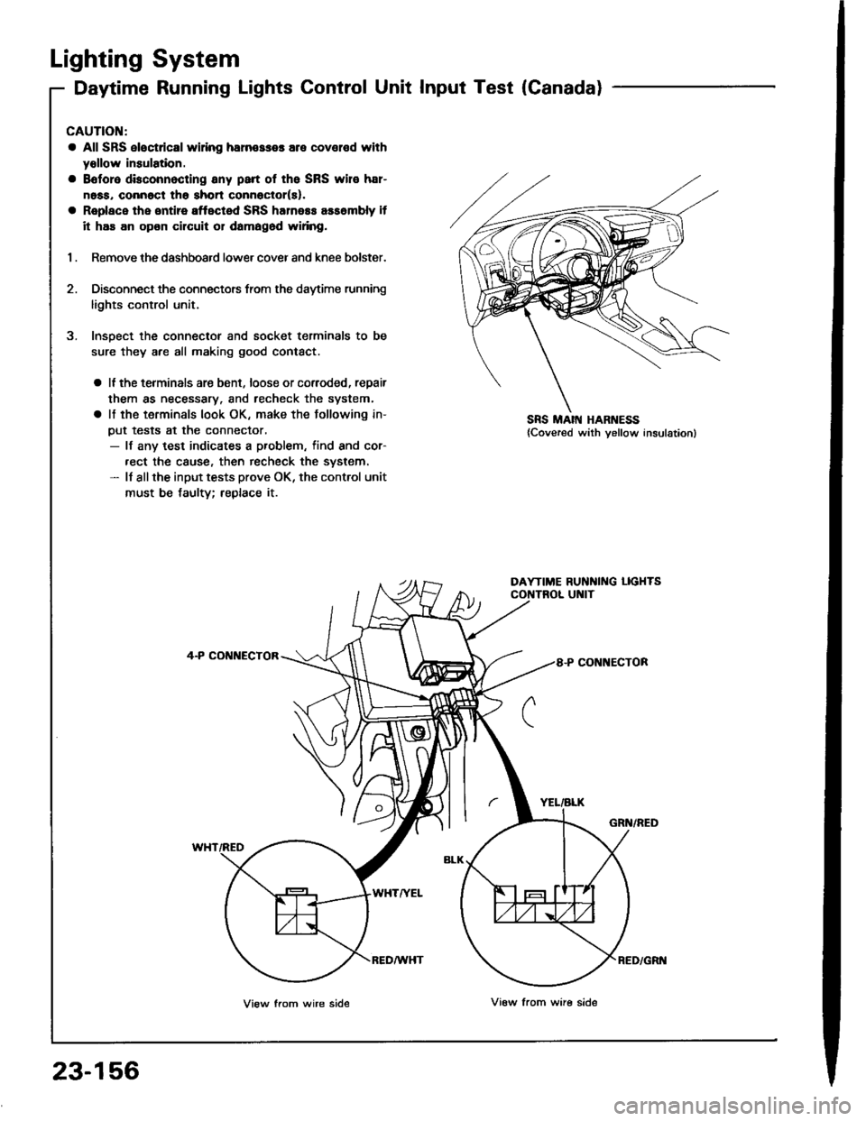
Lighting System
Daytime Running Lights Control Unit Input Test (Canada)
CAUTION:
a All SRS eloc{dcal wi ng harn€sses are covelod with
yollow insulation.
a Boforo dbconnocting any psrt of the SRS wir€ h8r-
noss, connoct tho shon connector(s).
a Roplace the entire affected SRS harness assombly it
it has an opon Gilcuit or damagod wifng.
1 . Remove the dashboard lower cover and knee bolster.
2. Disconnect the connectors from the daytime running
lights control unit.
3. Insoect the connectof and socket terminals to be
sure they are all making good contact.
a ll the terminals are bent, loose or coroded, repair
them as necessary. and recheck the system,
a lf the terminals look OK, make the following in-
put tests at the connector,- lf any test indicates a problem, find and cor-
.ect the cause, then recheck the system.- ll allthe input tests prove OK, the control unit
must be taulty; replace if
4-P CONI{ECTOR
WHT/RED
YEL/ALK
8-P CONNECTOR
GRN/RED
WHTA'EL
23-156
View from wire sideVi6w from ware side
RED/GRI{
Page 1264 of 1413
Lighting System
Combination Light/Turn Signal Switch Test
CAUTION:
a Atl SRS Oloctricsl wiring harnesses ar6 covered with
yellow insulation.
a Bslor€ disconnecting any pan ot the SRS wire har-
ness, connact the short connsctollsl.
a Replace the sntire aftectad SRS harne$ assembly if
it has an opon circuit or damagod wiring.
1. Remove the dashboard lower cover and steering
column covers (see page 23-71).
2. Disconnect the 4-P and 7-P connectors from the
switch.
3. Check the connector and socket tetminals to be sure
they are all making good contact. lf the terminals are
bent, loose, or cotroded, repair them as necessary,
and recheck the system.
4. Check tor continuitv between the terminals in each
switch position according to the table.
SRS MAIN HAR ESS
B
D
G
H
4-P CONI{ECTOR
7.P CONNECTOR
23-158
Page 1266 of 1413
Lighting System
Combination Light Switch
Replacement'1. Remove the steering column covers.
Disconnect the 4-P and 7-P connectors from the
combination lighr switch, then remove the two
screws and lift out the switch.
Daytime Running Lights Resistor
UPP€R COVER
Test lCanada)
CAUTION: The daytime running lights resistor becomas
vely hot when the daytime running lights are on; do not
touch it or the attaching hardware immediately aftel th€
lights h8ve b€en turned otf.
1. Disconnect the 3-P connector from the resistor.
DAYTIME RUNNINGLIGHTS RESISTOR
Measure the resistance between the resistor termi-
nals (A and B) and the Dower terminal C.
R€sistance: 1.4 O I O.O7 O
Replace the resistor with a new one if any ot the
resistances are bevond soecification.
?nd
V-c
View trom lerminal side
23-160
Page 1332 of 1413
Power Windows
Master Switch Input Test (Sedan)
NOTE; The control unit is built into the Dower window
maste. switch, and onlv controls driver's door window
ooerations.
1. Remove the driver's door panel and disconnect the
16-P and 1-P connectors from the master switch.
2. Inspect the connector and socket terminals to be
sure they are all making good contact.
a lf the terminals are bent, loose or co.roded, reDair
them as necessary. and techeck the system.a It the terminals look OK, make the following in-
put tests at the connecto..- It a test indicates a problem, tind and correct
the cause, then recheck the system.- lf allthe input tests prove OK, the power win-
dow master switch must be faulty; replace it.
23-226
BEDI'EL I GRN
8LU/YEL I YEL/BLK
View from wire side
View lrom wire side