1994 HONDA INTEGRA lash
[x] Cancel search: lashPage 1172 of 1413

Battery
a Battory tluid (6lectrolyt€l contains sulturic acid. lt may cauaa aevere burns iI it gots on your skin or in youl oyos.
Woar protoctivo clothing and I fac€ shield,- ll aloctrolyt6 gots on youl skin or clothos, rimo it off with wator immediately,- lf eloclrolyto g6ts in your oyos, tlush it out by splashing wat6r in youl eyes for at least 15 minutes; call a physiclan
immediately,
a A battery gives off hydrogon gas, lf ignit6d. tha hydrogsn will orploda and could crack tho baflory cas6 and splattor
acid on you. Koep spa*s. flames, and cigarottos away from the baftery.
a Overcharging will raiso ths tempelature ot th€ electrolyte. This may force electrolyte to splay out of the battery venta.
Follow lhe chargor manutacturer's instluctions and chargo tho battory at a prop61 rate.
NOTE: The original radio has a coded theft protection circuit. lt service to the car requires any of the lollowing, be sure
to get the customer's code number before- disconnecting the battery.- removing No. 32 (7.5 Al fuse from the under-hood fuse/relay box- removing the radio,
After service, reconnect power to the radio and turn it on. When the word "CODE" is displayed, enter the customer's
s-digir code to restore radio operation,
Use either a JCI or Bear ARBST tester, and follow the manufacturer's procedures. It you don'r have one of these com-puterized testers, follow this conventional test procedure:
To get accurate results, the temperature ot the electrolyte must be between TOoF l21ool and IOOoF {38oCl.
lf the case is cracked or the posts are loose,
replace the battery.
lf the indicator shows low electrolvte, add
distilled water it oossible.
Test Load Cspacity (# 1)
. Apply 3OO amp losd fo. 15 seconds to remove
surJace charge.. Allow 15 seconds recovery period.. Apply test load (see Test Load Chartl.. Record voltage at the end of 15 seconds.
Voltage stays above 9.6
volts: The batterv is OK.
23-66
Page 1250 of 1413
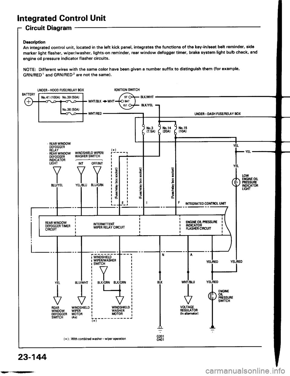
Integrated Control Unit
Circuit Diagram
D.3c ptlon
An integrat€d control unit, located in the left kick panel, integratss the functions of tho keyin/seat beh r6mind€r, sido
markar light {lasher, wiper/washer, lights-on r6minder, rear window dsfogger timer, brak€ system light bulb check, and
enging oil pressure indicator flasher circuitE,
NOTE: Difforent wires with the same color have be6n given a numbor suffix to distinguish them (for Example,
GRN/RED1 and GRN/RED'� are not the same).
WNOSHIELD WIPER/WASHER SWITCH
IMT OFFiINT
I
II
IIIIIIIIIIII
YEUEE
rl
t
P
UNOER - DASH FUS€/RETAY BOX
r NTEGRATED COI{TROI UNIT
t-0wErGrilE 0|lPRESSI'REINDICATORLIGI{T
WINDSHIELOWIPERAVASHERswtTcH
tr-/
IBLK/GRN BI
WINDSHIELOWIPERMOTOR{Asl
VOLTAGEREGULATOR{ln ahamator,
UNOER- HOOD FUSE/RELAY 8OX
I
r3
r8relit;rBt5I
23-144
lr ) : With combinod washef-wip€r oporation
Page 1254 of 1413
Integrated Control Unit
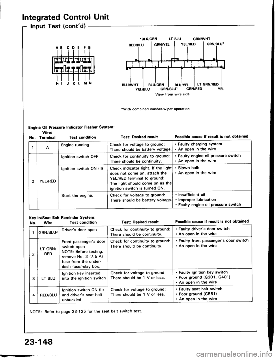
Input Test (cont'd)
Engine Oil Pressure Indicator Flashal System:
Wire/
rWith combined washeFwipot operation
Test: Desired resultPossiblo c€use if r6rult is not obtainodNo. TelminalTsst condition
M
1Engine runningCheck for voltage to ground:
There should be battery voltage
. Faulty charging system. An oDen in the wire
YEL/RED
lgnition switch oFFCheck for continuity to gtound:
There should be continuitv.
. Faulty engine oil ptessure switch
. An oDen in the wire
lgnition switch ON (ll)Check indicator light. lf the light
does not come on, Sttach the
YEL/RED terminal to ground:
The light should come on as the
ignition switch is turned ON.
. Blown bulb. An open in the ware
Start the engine.Check for voltage to ground:
There should be battery voltage
Insufficient oil
lmproper lubrication
Faulty engine oil pressure switch
Key-in/Seat Bolt Reminder Systam:
No. WilaTest condition
NOTE: Refer to page 23-125 for the seat belt switch test.
Test: Dosired lesuhPossible causo if resuh is not obtainod
23-148'
GRN/BLU'Driver's door openCheck for continuity to ground;
There should be continuitv.
. Faulty driver's door switch
. An ooen in the wire
LT GRN/
RED
Front passenger's door
switch open
NOTE: Betore testing,
remove No. 3 (7.5 A)
tuse from the under-
dash fuse/relay box.
Check tor continuity to ground:
There should be continuitv.
. Faulty lront passenger's door switch
. An ooen in the wire
LT BLU
lgnition key inserted
into the ignition switch
Check for voltage to ground:
There should be 1 V or less.
Faulty ignition key switch
Poor ground (G201 , G401)
An ooen in the wite
RED/BLU
lgnition switch ON (ll)
and driver's seat belt
unbuckled
Check lor voltage to ground:
There should be 1 V or less.
Faulty seat belt switch
Poor ground {G551)
An open in the wire
;.rqFft,
Page 1255 of 1413
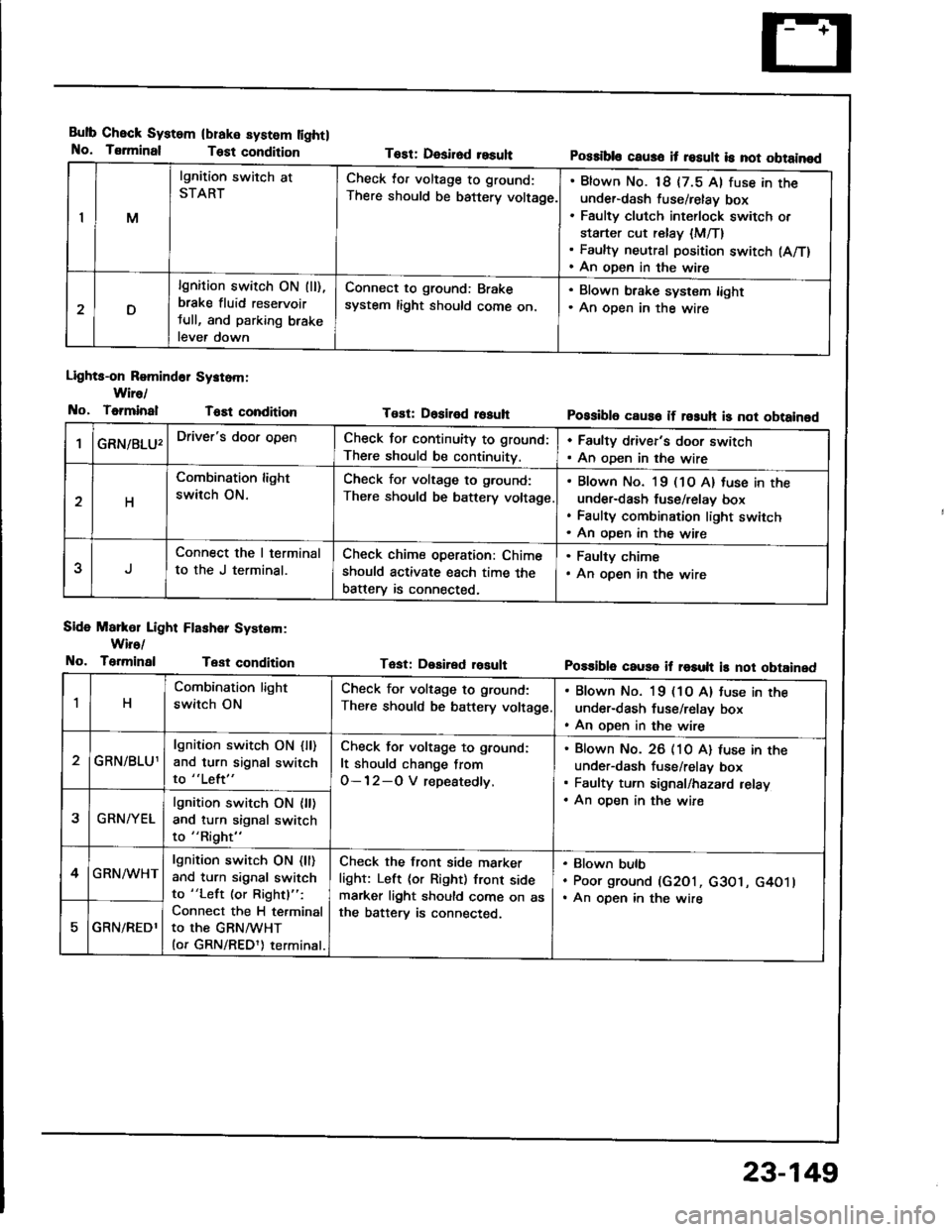
Bulb Check System
No. Tsrminal
(blake system lightl
Test condition
Lights-on Romind6r Systom:
Wire/
No, ToiminalT6Et condition
Side Markol Light Flashar System:
Wiro/
No. TerminalTest condition
Tost: Desirod resuhPossibls caus6 it result is not obtainod
Tost: Dositod rosuhPossibl6 caus6 if rosuh is not obtainod
Tast: Desired rosultPo$ible cause if result is not obtained
IM
lgnition switch at
STARTCheck lor voltage to ground:
There should be battery voltage.
Blown No. 18 {7.5 Al fuse in theunder-dash fuse/relay box
Faulty clutch int€rlock switch or
starter cut relay {M/T}Faulty neutral position switch (A/T)
An open in the wire
D
lgnition switch ON (ll),
brake fluid reservoir
tull, and parking brake
lever down
Connect to ground: Brake
system light should come on.
. Blown brake system light. An oDen in the wire
GRN/8LU'Driver's door openCheck for continuity to ground:
There should be continuity.
. Faulty driver's door switch. An oDen in the wire
H
Combination light
switch ON.
Check for voltage to g.ound:
There should be battery voltage
Blown No. l9 (1O A) tuse in the
under-dash fuse/relav box
Faulty combination light switch
An oDen in the wire
5
Connect the I terminal
to the J terminal.
Check chime operation: Chime
should activate each time the
batterv is connected,
. Faulty chime. An open in the wire
1H
Combination light
switch ON
Check for voltage to ground:
There should be battery voltage
. Blown No. 19 (1O A) tuse in the
under-dash fuse/relay box. An open in the wire
GRN/BLU1
lgnition switch ON {ll)and turn signal switch
to "Left"
Check for voltage to ground:
It should change from
O-12-O V repeatedly.
Blown No. 26 (10 A) luse in theunder-dash fuse/relav box
Faulty turn signal/hazard relay
An oDen in the wire2GRN/YEL
lgnition switch ON {ll)and turn signal switch
to "Right"
4GRN/WHTlgnition switch ON (ll)
and turn signal switch
to "Left (or Rightl":
Connect the H terminal
to the GRNMHT(or GRN/REDl) terminal.
Check the front side marker
light: Left (or Right) front sidemarker light should come on asthe batterv is connected.
Blown bulb
Poor ground (G2O1, c3O1, G4O1lAn open in the wire
GRN/REDl
23-149
Page 1257 of 1413
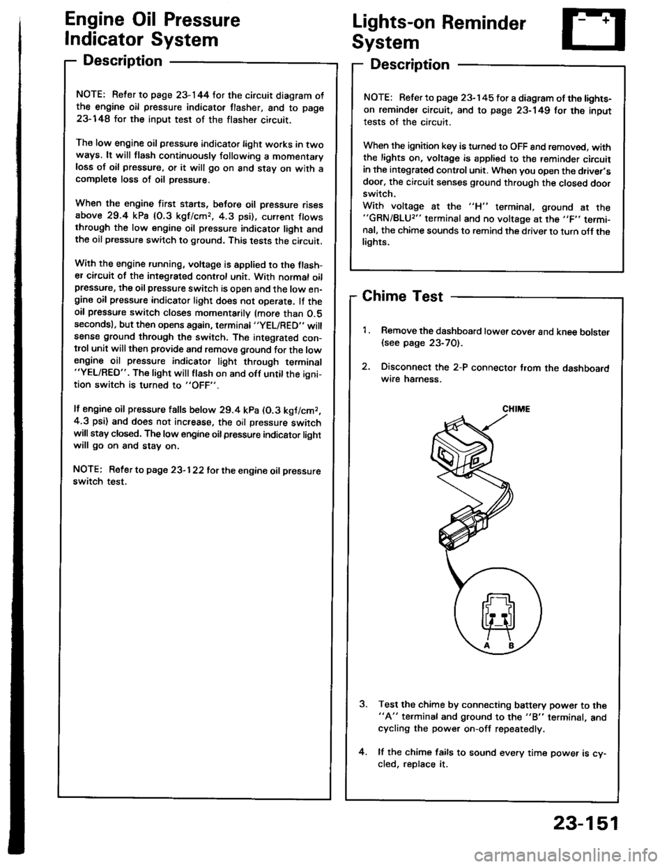
Engine Oil Pressure
Indicator System
Description
NOTE: Reter to page 23-144 tor the circuit diagram otthe engine oil pressure indicator flasher, snd to page
23-148 lor the input test of the flasher circuit.
The low engine oil pressure indicator tight works in twoways. lt will flash continuously following a momentaryloss of oil pressure, or it will go on and stay on with acomplete loss of oil pressure.
When the engine first starts, before oil Dressure risesabove 29.4 kP8 10.3 kgf/cmr, 4.3 psi), current flowsthrough the low engine oil pressure indicator light andthe oil pressure switch to ground. This tests the circuit.
Wilh the engine running, voltage is applied ro the ftash-er circuit of the integrated control unit. With normal oilpressure, the oil pressure switch is open and the low en-gine oil pressure indicator light does not operate. lf theoil pressure switch closes momentarily (more than O.5secondsl, but then opens again, terminal "yEL/RED,'will
sense ground through the switch. The integrated con-trol unit willthen provide and remove ground for th€ lowengine oil pressure indicator light through terminal"YEL/RED". The light will flash on and olf until the igni-tion switch is turned to "OFF".
lf engine oil pressure falls below 29.4 kPa (O.3 kgJ/cmr,4.3 psi) and does not increase, the oil pressure switchwillstsy closed. The low engine oilpressure indicator lightwill go on and stav on.
NOTE; Refer to page 23-122lot the engine oil pressure
switch test.
Lights-on Reminder
System
Description
Chime Test
Remove the dashboard lower cover and knee bolster
{see page 23-70).
Disconnect the 2-P connector t.om the dashboardwire hamess.
Test the chime by connecting battery power to the"A" te.minal and ground to the "B" terminal, andcycling the power on-off repestedly.
lf the chime fails to sound every time power is cy-cled, reDlace it.
NOTE: Refer to page 23-145 tor a diagram of the lights-
on reminder circuit, and to page 23-149 for the input
tests of the circuit.
When the ignition key is turned to OFF 8nd removed. withthe lights on, voltage is apptied to the reminder circuitin the integrat€d control unit. When you open the driver,sdoor, the circuit senses ground through the closed doorswitch.
With voltage at the "H" terminal, ground at the"GRN/BLU2" terminal and no voltage at the ,,F,' termi-nal, the chime sounds to remind the driver to turn oJf thelights.
CHIME
23-151
Page 1290 of 1413
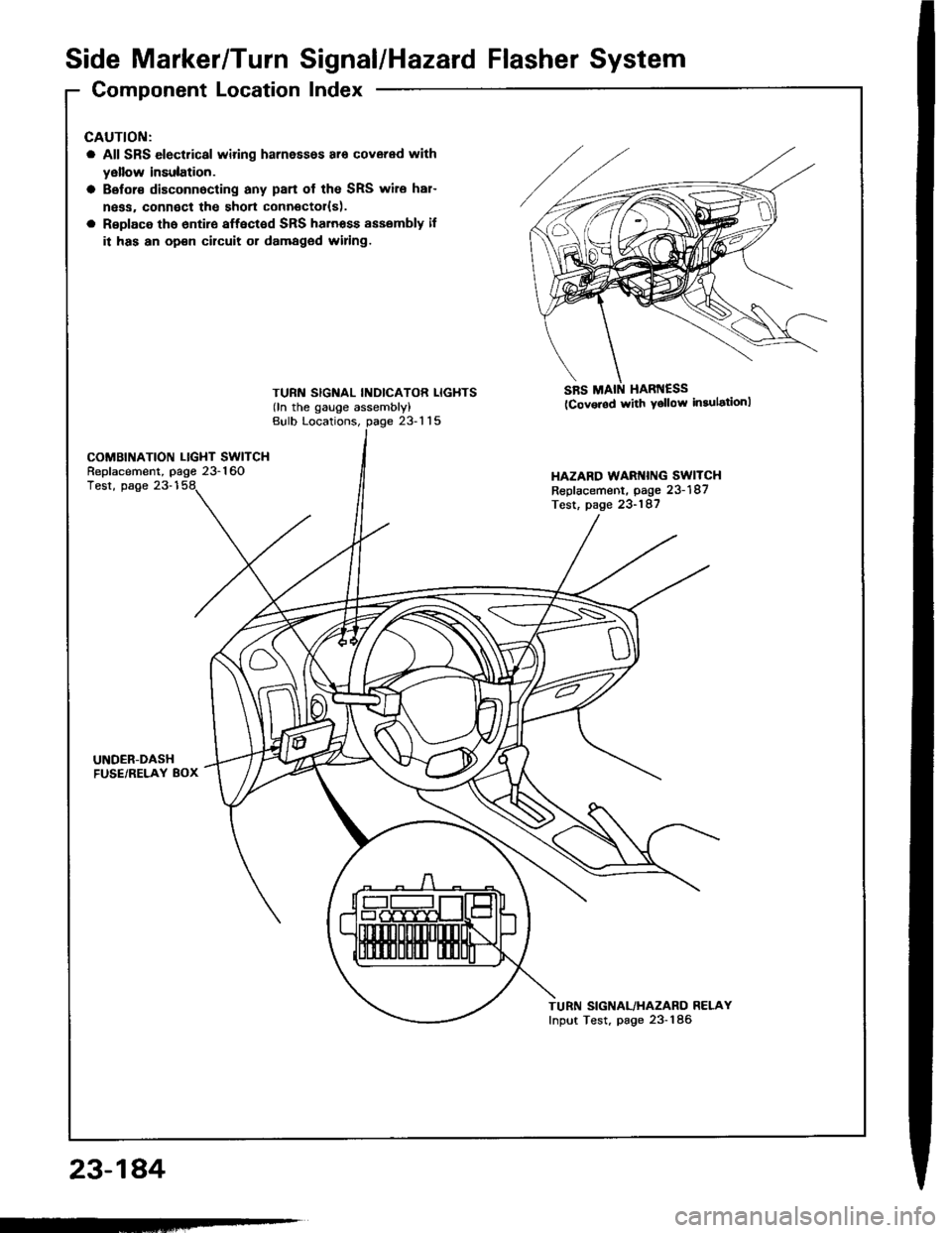
Side Marker/TurnSignal/Hazard Flasher System
Component LocationIndex
23-184
GAUTION:
a All SRS electrical wiring harnessos ar6 covered with
yellow insulation.
a Belor€ disconnocting any pan of the SRS wire har-
ngss, connoct the short connector{s).
a Rsplace tho 6ntir€ affect€d SRS harnoss sssembly il
it has an op€n cilcuit or damaged widng.
TURN SIGNAL INDICATOR LIGHTS(ln the gauge assembly)
SRS MAIN HARI{ESS(Cov.rod with Ysllow in3ulationl
Bulb Locations,23-115
COMBINATION LIGHT SWITCHReplacement, page 23-160HAZARD WARI{ING SWITCHReplacement, page 23-187Test, page 23-187
Test, page 23-1
UNDER-DASHFUSE/RELAY 8OX
TURN SIGNAL/HAZARO RELAYInput Test, page 23-186
-
Page 1291 of 1413
UNDEN-HOOD FUSE/RELAY 8OX
N0.41 1100A) No.40 (50A)
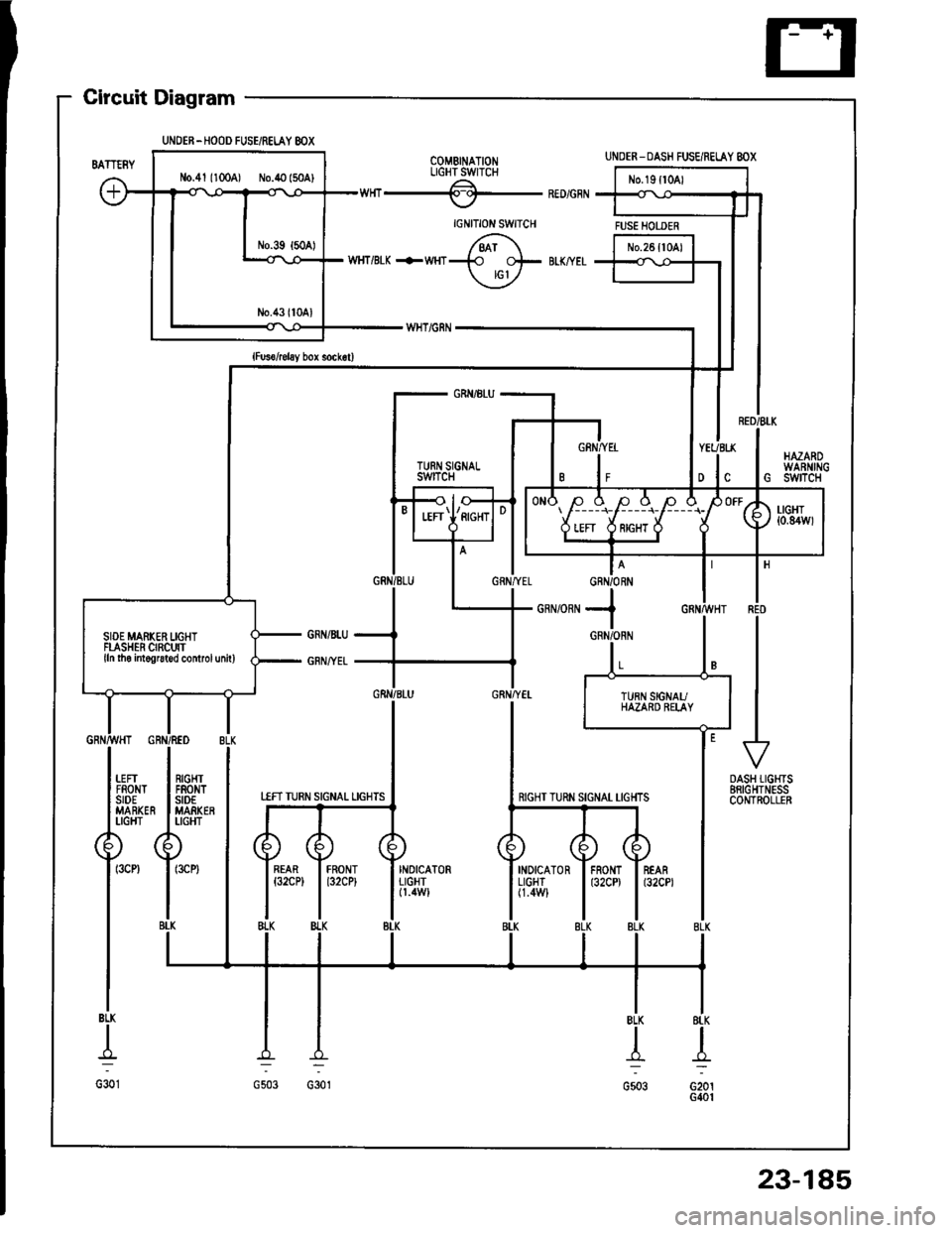
Gircuit Diagram
COMBINATIONLIGHTSWTCHA.---of-RED/GRN
IGNITION SWITCH
/6i\WHT/BTK +WHT+ +- BIK/YET
\jv
UNDER-DASH FUSE/RELAY 8OX
FUSE HOTJER
GRN/BtU
TURN SIGiIALswtTcH
I
|l
+DASH TIGHTSBRIGHTNESSCONTROLLER
SIOE MAFKER LIGHTFLASHER CIRCUITlln tho intogruted controlunitl
RIGHT TURN SIGNAT TIGHTS
INOICATOR I FRONT I REARL|GHT I t32CD I t32CPl(1.4W1
23-185
Page 1292 of 1413
Side Marker/Turn Signal/Hazard Flasher System
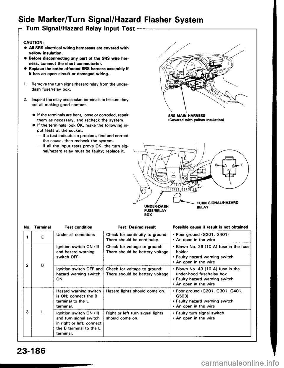
Turn Signal/Hazard Relay Input Test
CAUTION:
a All SRS electrical wiring harn6ss6s ar€ covered with
yellow insulation.
a B€foro disconn6cting any part of th€ SRS wire har-
noss, connoct tho short connector(s).
a Replaco tho ontiro sftoctod SRS harness ass€mbly it
it has an open circuit or damagod wiring,
I . Remove the turn signal/hazard relay from ths under-
dash Juse/relay box.
2. Inspect the relay and socket terminals to be sure they
are all making good contact.
a It the terminals are bent, loose or coroded, repair
them as necessary, and recheck the system.
a lf the terminals look OK, make the tollowing in-
put tests at the socket.- lf a test indicates a problem, find and correct
the cause, then recheck the system.- lf all the input tests prove OK, the turn sig-
nal/hazard relay must be taulty; replace it.
UI{DEB-DASHFUSE/RELAYBOX
Test: D€sired rosult
SBS MAIN HAR ESS{Covg.ed with yollow inrulltion)
TelminalTeEt conditionPo$iblo causo it fosult is not obtainod
,lEUnder all conditionsCheck for continuity to ground:
There should be continuitv.
. Poor ground (G201 , G4O1). An oDen in the wire
2B
lgnition switch ON (ll)
and hazard warning
switch OFF
Check for voltage to ground:
There should be battery voltage.
Blown No. 26 (10 A) fuse in ths fuse
holder
Faulty hazard warning switch
An open in the wire
lgnition switch OFF and
hazard warning switch
ON
Check for voltage to ground:
There should be battery voltage.
Blown No. 43 (10 Al fuse in the
under-hood fuse/relay box
Faulty hazard warning switch
An ooen in the wire
3
Hazard wa.ning switch
is ON; connect the B
terminal to the L
termrnat.
Hazard lights should come on.Poor ground (G2O1, G3O1, G4O1
G503)
Faulty hazard warning switch
An open in the wire
lgnition switch ON (lll
and turn signal switch
in right or left; connect
the B terminal to the L
terminal.
Right or left turn signal lights
should come on.
. Faulty turn signal switch. An open in the wire
23-186
-